EP1215015A2 - Verfahren und Vorrichtung zur Unterbrechung einer Vorschubbewegung - Google Patents
Verfahren und Vorrichtung zur Unterbrechung einer Vorschubbewegung Download PDFInfo
- Publication number
- EP1215015A2 EP1215015A2 EP01129180A EP01129180A EP1215015A2 EP 1215015 A2 EP1215015 A2 EP 1215015A2 EP 01129180 A EP01129180 A EP 01129180A EP 01129180 A EP01129180 A EP 01129180A EP 1215015 A2 EP1215015 A2 EP 1215015A2
- Authority
- EP
- European Patent Office
- Prior art keywords
- drive
- feed movement
- reference surface
- tool
- movement
- Prior art date
- Legal status (The legal status is an assumption and is not a legal conclusion. Google has not performed a legal analysis and makes no representation as to the accuracy of the status listed.)
- Withdrawn
Links
Images

Classifications
-
- B—PERFORMING OPERATIONS; TRANSPORTING
- B25—HAND TOOLS; PORTABLE POWER-DRIVEN TOOLS; MANIPULATORS
- B25F—COMBINATION OR MULTI-PURPOSE TOOLS NOT OTHERWISE PROVIDED FOR; DETAILS OR COMPONENTS OF PORTABLE POWER-DRIVEN TOOLS NOT PARTICULARLY RELATED TO THE OPERATIONS PERFORMED AND NOT OTHERWISE PROVIDED FOR
- B25F5/00—Details or components of portable power-driven tools not particularly related to the operations performed and not otherwise provided for
- B25F5/02—Construction of casings, bodies or handles
- B25F5/021—Construction of casings, bodies or handles with guiding devices
-
- B—PERFORMING OPERATIONS; TRANSPORTING
- B25—HAND TOOLS; PORTABLE POWER-DRIVEN TOOLS; MANIPULATORS
- B25B—TOOLS OR BENCH DEVICES NOT OTHERWISE PROVIDED FOR, FOR FASTENING, CONNECTING, DISENGAGING, OR HOLDING
- B25B21/00—Portable power-driven screw or nut setting or loosening tools; Attachments for drilling apparatus serving the same purpose
-
- B—PERFORMING OPERATIONS; TRANSPORTING
- B25—HAND TOOLS; PORTABLE POWER-DRIVEN TOOLS; MANIPULATORS
- B25B—TOOLS OR BENCH DEVICES NOT OTHERWISE PROVIDED FOR, FOR FASTENING, CONNECTING, DISENGAGING, OR HOLDING
- B25B23/00—Details of, or accessories for, spanners, wrenches, screwdrivers
- B25B23/0064—Means for adjusting screwing depth
Definitions
- the invention relates to a device with which the feed movement a tool can be interrupted, and a method for Interruption of such a feed movement.
- the invention has for its object the feed movement of a To design the tool so that it can be easily predefined correct position is interrupted so that later manual adjustment work is not necessary.
- the invention proposes a device the features mentioned in claim 1 and a method with the features mentioned in claim 11. Further training of the Invention are the subject of dependent claims.
- the device thus contains an input, for example a shaft.
- This input is connected to or is with the drive connected.
- With the entrance, for example, is always the Output connected to that in the example mentioned above Screwdriver bit is engaged. So when the drive is actuated, it happens screwing a screw into a substructure, the Screw, for example, is connected to a board so that it is is fixed at the head of the screw.
- the screw movement the device and thus a fixed distance from the device showing panel reaches the plane of the beam, the motion becomes of the output and thus the feed movement is stopped. With in other words, the feed takes place automatically until the Sensor reaches the reference plane defined by the beam.
- a rotating laser beam can be used to define the reference plane be used, which is perpendicular to an axis of rotation.
- Such devices are available on the market. You can when in visible area, one from the user's eye create a perceptible line, for example a red line. On Such a device can be used by the invention without a user needs to intervene. The laser beam does not need to be visible his.
- the Input and output of the device constantly with each other are operatively connected, then the stopping device on the drive acts.
- the device switches the drive or the output from a clutch or the like.
- the Device as the invention proposes in development, part of a Device that contains the drive.
- the Device be installed in a screwdriver, which then to the purpose mentioned above can be used.
- the device as a separate Device is designed with a device containing the drive can be connected.
- a device containing the drive can be connected.
- the device can be used as a front attachment for one Screwdriver or other drive device may be formed.
- the Device has a possibility in connecting the Device with the drive also the control connection manufacture.
- the device is a coupling device between the entrance and the exit, which of the Stopping device is controllable. This would be the case with the mentioned Example of a tightening process means that when the Reference surface, the clutch device is disengaged so that the The drive continues to rotate, but the output shaft with the tool is no longer driven.
- a control connection to the drive is not possible or on the other hand the drive is not fast enough can be switched off.
- the Device has a timer that a certain time after the Disengaging the clutch device engages it again. If the Clutch device is disengaged, the user realizes that he is with is done. He can now focus on the next screw focus, and if he tries to screw them in, he will the feed is available again. Because at this time it is Coupling device has been engaged again.
- the invention can with all types of feed movements of Tools are used, but it is particularly cheap at a feed movement which is designed as a screw movement. It can also be a unscrewing process.
- the beam that defines the reference plane can be act in particular a laser beam, especially a laser beam in the visible area. It is possible to design the sensors that they respond selectively to this laser beam. It can therefore existing laser beam devices can be used.
- the Device have more than one sensor, for example two Sensors. These can be arranged so that the Laser beam received at different locations in the same plane can.
- the procedure for interrupting the feed movement is exemplified by the process of screwing on a ceiling, carried out as follows. First, a laser beam device is like this installed that it defines a correct reference plane. The distance from the tip of the screwdriver bit to the sensors Establishment of the reference plane considered. Then one first screw screwed into the ceiling with a wooden board without that the fitter takes closer account of certain dimensions takes. As soon as you screw in the screw, the sensor of the device the reference plane reaches what he does by detecting the laser beam notices, the feed movement is interrupted. The fitter notices this and pulls the screwdriver back. He can now screw the next one screw in the same way.
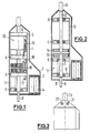
- the device proposed by the invention is in the shown embodiments as an attachment for a drill educated.
- the device is in a smooth housing 1 housed, for example, a square or has a rectangular cross-section, which is laterally through an extension 2 is added. In this approach 2 there is a compartment 3 for batteries 4 accommodated.
- a frame 5 is held within the housing which the housing is fixed.
- the frame 5 has four across Longitudinal axis of the device extending plates 6 for storage serve different parts.
- FIG. 2 is a longitudinal section through the device through the axis of the device.
- This first shaft faces the one from the housing 1 protruding end 8 opposite end a gear 10, which is firmly connected to the shaft 7.
- the shaft 7 represents the illustrated embodiment, the input shaft or more generally said the entrance. In the space between the two plates 6 there is space for part of the electronics 11, for example.
- the shaft 12 has a receptacle 13 for one bit.
- the Shaft 12 provided with a gear 14, which is identical to that Gear 10 of the first shaft 7 is formed.
- the two gears 10, 14 have a small axial distance from one another.
- the one with the Recording 13 for the tool shaft 12 is the Output shaft. It can also be used as a general exit from the Device are called.
- Storage of the output shaft 12 serving plates 6 is space for one Electric motor 15, the function of which will be described later.
- a drill chuck could also be attached to a bit holder, since with the device is of course possible.
- a coupling device 16 arranged, which has a shift drum 17 with a gear 18.
- the Shift drum 17 is axially displaceable in the two plates 6 mentioned stored.
- the gear wheel 18 has an axial length which is axial Extension of both gears 10, 14 and the space between corresponds to this.
- the shift drum 17 is with the electric motor 15 connected that actuation of the electric motor 15 the shift drum axially so that the gear 18 out of engagement with that of the Input shaft associated gear 10 pulls. In this position the Shift drum 17 still stored in both plates 6.
- the pulling out of the gear 18 out of engagement with the gear 10 takes place against the Effect of a tension spring 19, which is indicated in Figure 1.
- the two shafts 7, 12 are the Device not connected.
- the coupling device there is a connection of the two gears 10, 14 and thus of the two shafts 7, 12.
- This rotary connection of the two shafts can by operating the electric motor 15 in the one just described Way to be lifted.
- two sensors 20, 21 arranged on the radiation respond to a laser beam used for the device. Both Sensors 20, 21 have the same from the end of the receptacle 13 axial distance. They are arranged with one in the device Electronics 11 connected, which is also a timer for the Operation of the device.
- the two gears 10, 14 by the gear 18th the coupling device 16 connected to each other.
- the Laser steel hits one of the two sensors 20, 21, switches the Electronics the electric motor 15, which is powered by the Batteries 4 receives.
- the electric motor pulls the shift drum 17 upwards against the action of the spring 19.
- the gear 18 disengages with the gear 10 assigned to the input shaft 7. After a The servomotor is determined by the electronics brought from the tension spring 19 in the starting position, so that Gear 18 comes into engagement with gear 10 again.
- the device proposed by the invention is as follows used.
- the attachment is with its neck 8 in a drill chuck of a screwdriver.
- the screwdriver bit is in the recording 13 inserted at the opposite end of the device.
- To the Assembling a horizontal ceiling plate is now a screw used, which is screwed into the device.
- the Reference plane is represented by a rotating or a back and forth oscillating laser beam defined.
- the drive stops, even if the The drill or the electric screwdriver continues to run. The user notices the stopping immediately. He knows that he is in the correct position Has. He removes the device from the screw and turns the next place where he wants to screw in a screw. If so what is far is that he can screw in the next screw, that has Timed the clutch device is engaged again, so that it without can continue to work.
- the invention has been described using an example in which the Device is designed as an attachment.
- the device can Of course, it can also be installed in a device that has a screwdriver drive contains.
- the device can also be used for other types of feed movements can be used, for example with beating feed movements.
- Fig. 4 shows another embodiment in which the of the invention proposed device is also designed as an attachment.
- the blind hole with the thread is dimensioned so that the attachment as far as possible on a drive machine can be screwed on.
- the other facilities at the previous Embodiment described in detail are within the Housing 31 housed. At the transition between the housing 31 and the output 32, the two sensors 33 are arranged.
- the Output 32 can either be used as a chuck or as a bit holder be trained.
Landscapes
- Engineering & Computer Science (AREA)
- Mechanical Engineering (AREA)
- Details Of Spanners, Wrenches, And Screw Drivers And Accessories (AREA)
Abstract
Description
- Fig. 1
- eine Seitenansicht einer von der Erfindung vorgeschlagenen Vorrichtung mit geschnittenem Gehäuse;
- Fig. 2
- einen Schnitt etwa durch eine die Achse enthaltende Ebene;
- Fig. 3
- eine Detailansicht des Gehäuses im Bereich des Abtriebsteil;
- Fig. 4
- eine Seitenansicht einer Vorrichtung als Zusatzteil.
Claims (14)
- Vorrichtung zur Unterbrechung einer Vorschubbewegung eines Werkzeugs an einer durch einen quer zur Vorschubrichtung verlaufenden Strahl bestimmten Stelle, mit1. 1 einem Eingang (7), der1.1.1 mit einem Antrieb zur Erzeugung der Vorschubbewegung verbindbar bzw. verbunden ist,1.2 einem Ausgang (12), der1.2.1 mit dem Eingang (7) mindestens während der Vorschubbewegung wirkverbunden ist und1.2.2 mit dem das Werkzeug in Eingriff steht,1.3 mindestens einem Sensor (20, 21) zum Erfassen des Stahls bei Erreichen der vorbestimmten Stelle, sowie mit1.4 einer Einrichtung zum Anhalten der Bewegung des Ausgangs, die1.4.1 von dem Sensor (20, 21) ansteuerbar bzw. auslösbar ist.
- Vorrichtung nach Anspruch 1, bei der der Eingang (7) und der Ausgang (12) ständig miteinander wirkverbunden sind und die Anhalteeinrichtung auf den Antrieb einwirkt.
- Vorrichtung nach Anspruch 1 oder 2, ausgebildet als Teil eines den Antrieb enthaltenden Gerätes.
- Vorrichtung nach Anspruch 1 oder 2, ausgebildet als Vorsatzgerät, das mit einem den Antrieb enthaltenden Gerät verbindbar ist.
- Vorrichtung nach Anspruch 4, bei der eine Verbindung zwischen dem Antrieb und der Anhalteeinrichtung herstellbar ist.
- Vorrichtung nach einem der Ansprüche 1 und 3 bis 5, mit einer Kupplungseinrichtung (16) zwischen dem Eingang (7) und dem Ausgang (12), die von der Anhalteeinrichtung ansteuerbar ist.
- Vorrichtung nach einem der vorhergehenden Ansprüche, bei der die Anhalteeinrichtung nach Ablauf einer bestimmten Zeit die Bewegung des Ausgangs wieder ermöglicht.
- Vorrichtung nach einem der vorhergehenden Ansprüche, bei der die Vorschubbewegung ein Schraubvorgang ist.
- Vorrichtung nach einem der vorhergehenden Ansprüche, bei der der Strahl ein Laserstrahl ist.
- Vorrichtung nach einem der vorhergehenden Ansprüche, mit zwei Sensoren (20, 21).
- Verfahren zum Unterbrechen der Vorschubbewegung eines Werkzeugs an einer bestimmten Stelle, bei dem11.1 ein Strahl zur Definition einer quer zur Vorschubbewegung verlaufenden Bezugsfläche verwendet wird,11.2 das Werkzeug quer zur Bezugsfläche vorwärts bewegt und11.3 die Vorschubbewegung angehalten wird, sobald das Werkzeug die Bezugsfläche erreicht.
- Verfahren nach Anspruch 11, bei dem ein um eine ortsfeste Achse rotierender bzw. schwenkender Strahl verwendet wird.
- Verfahren nach Anspruch 11 oder 12, bei dem das Erreichen der Bezugsfläche durch einen Sensor (20, 21) festgestellt wird.
- Verfahren nach einem der Ansprüche 11 bis 13, bei dem bei Erreichen der Bezugsfläche eine die Vorschubbewegung ermöglichende Kupplung (16) ausgerückt wird.
Applications Claiming Priority (2)
| Application Number | Priority Date | Filing Date | Title |
|---|---|---|---|
| DE10061830 | 2000-12-12 | ||
| DE10061830A DE10061830A1 (de) | 2000-12-12 | 2000-12-12 | Verfahren und Vorrichtung zur Unterbrechung einer Vorschubbewegung |
Publications (2)
| Publication Number | Publication Date |
|---|---|
| EP1215015A2 true EP1215015A2 (de) | 2002-06-19 |
| EP1215015A3 EP1215015A3 (de) | 2003-05-02 |
Family
ID=7666802
Family Applications (1)
| Application Number | Title | Priority Date | Filing Date |
|---|---|---|---|
| EP01129180A Withdrawn EP1215015A3 (de) | 2000-12-12 | 2001-12-10 | Verfahren und Vorrichtung zur Unterbrechung einer Vorschubbewegung |
Country Status (2)
| Country | Link |
|---|---|
| EP (1) | EP1215015A3 (de) |
| DE (1) | DE10061830A1 (de) |
Cited By (2)
| Publication number | Priority date | Publication date | Assignee | Title |
|---|---|---|---|---|
| DE102013211516A1 (de) | 2013-06-19 | 2014-12-24 | Deere & Company | Anhängevorrichtung |
| DE102013211510A1 (de) | 2013-06-19 | 2014-12-24 | Deere & Company | Anhängevorrichtung |
Families Citing this family (3)
| Publication number | Priority date | Publication date | Assignee | Title |
|---|---|---|---|---|
| DE102005048162B4 (de) * | 2005-10-06 | 2011-11-10 | Bb International Of Naples Inc. | Vorrichtung zur Eindrehbegrenzung |
| DE102017220064B4 (de) * | 2017-11-10 | 2022-09-29 | Thyssenkrupp Ag | Einschraubvorrichtung zum automatisierten Einschrauben und Verfahren |
| CN111391029A (zh) * | 2020-03-25 | 2020-07-10 | 许云友 | 一种建筑材料用防倾斜的钻孔辅助设备 |
Family Cites Families (7)
| Publication number | Priority date | Publication date | Assignee | Title |
|---|---|---|---|---|
| US2796161A (en) * | 1955-07-26 | 1957-06-18 | Clinton L Graybill | Hydraulically actuated attachment for power-driven tool chucks |
| DE3615874A1 (de) * | 1986-05-10 | 1987-11-12 | Bosch Gmbh Robert | Verfahren zur messung der entfernung einer handwerkzeugmaschine von einem werkstueck |
| CH674573A5 (de) * | 1987-07-13 | 1990-06-15 | Wild Leitz Ag | |
| DE3818924A1 (de) * | 1987-12-08 | 1989-06-29 | Makita Electric Works Ltd | Kraftgetriebenes schraubwerkzeug |
| DE3813190A1 (de) * | 1988-04-20 | 1989-11-02 | Bosch Gmbh Robert | Schlagregelung fuer nagel- oder klammergeraet |
| US5484026A (en) * | 1993-09-03 | 1996-01-16 | Nikon Corporation | Handheld electromotive tool with sensor |
| ATE254230T1 (de) * | 1997-04-11 | 2003-11-15 | Dieter Peterhans | Vorrichtung zur nivellierung eines objektes |
-
2000
- 2000-12-12 DE DE10061830A patent/DE10061830A1/de not_active Withdrawn
-
2001
- 2001-12-10 EP EP01129180A patent/EP1215015A3/de not_active Withdrawn
Cited By (3)
| Publication number | Priority date | Publication date | Assignee | Title |
|---|---|---|---|---|
| DE102013211516A1 (de) | 2013-06-19 | 2014-12-24 | Deere & Company | Anhängevorrichtung |
| DE102013211510A1 (de) | 2013-06-19 | 2014-12-24 | Deere & Company | Anhängevorrichtung |
| EP2820933A1 (de) | 2013-06-19 | 2015-01-07 | Deere & Company | Anhängevorrichtung |
Also Published As
| Publication number | Publication date |
|---|---|
| DE10061830A1 (de) | 2002-06-13 |
| EP1215015A3 (de) | 2003-05-02 |
Similar Documents
| Publication | Publication Date | Title |
|---|---|---|
| DE60315637T2 (de) | Integriertes befestigungssystem | |
| DE3421452A1 (de) | Vorrichtung zum automatischen erfassen bzw. loesen eines werkzeugtraegers bei einem manipulator | |
| EP1961976A2 (de) | Befestigungseinheit | |
| DE102015205122B4 (de) | Schraubendreher | |
| WO2010012706A1 (de) | Schraubenantriebsausbildung | |
| DE202020106963U1 (de) | Elektrowerkzeug mit einem intelligent-erkennungsfähigen, trennbaren Arbeitskopf | |
| DE2220790A1 (de) | Handwerkzeug-einstellhuelse | |
| EP1305529A1 (de) | Dübel für leichtbaustoffe und verwendung eines schraubendreherbits zum einschrauben eines solchen dübels | |
| AT409988B (de) | Verfahren zum befestigen von holzkonstruktionsteilen vor einer betonwand oder mauer | |
| DE20208439U1 (de) | Schraubelement sowie Verbindungsteile zum Drehen des Schraubelementes | |
| EP0979358A1 (de) | Schraube | |
| DE3716808A1 (de) | Schraube | |
| DE10061830A1 (de) | Verfahren und Vorrichtung zur Unterbrechung einer Vorschubbewegung | |
| CH660774A5 (en) | Spacer screw | |
| EP0284894A1 (de) | Befestigungseinrichtung mit Schraube und Impulswerkzeug für universelle Befestigungen | |
| EP0237595A1 (de) | Sicherheitsschraube für unlösbare Verbindungen | |
| DE3150434A1 (de) | Abreisschraube | |
| DE4439973C2 (de) | Werkzeug zum Einbringen einer Schraubhülse in Baumaterial und zum Eindrehen einer Schraube in einen Aufnahmekanal der Schraubhülse | |
| DE3318941A1 (de) | Vorrichtung zum drehen und axialbewegen von bolzen | |
| CH671260A5 (de) | ||
| AT402335B (de) | Justierdübelsystem zur einstellbaren verbindung zweier elemente miteinander sowie eine gewindehülse, eine verankerungshülse, ein verankerungselement und eine bohrhilfe für das justierdübelsystem | |
| EP0196485A1 (de) | Vorrichtung zur Befestigung eines Bauteils an einer Mauer oder an einem anderen Gebäudeteil | |
| DE8816461U1 (de) | Sicherheitsschraube | |
| DE2618521C3 (de) | Gewindebohrfutter | |
| EP0180246B1 (de) | Schneidewerkzeug |
Legal Events
| Date | Code | Title | Description |
|---|---|---|---|
| PUAI | Public reference made under article 153(3) epc to a published international application that has entered the european phase |
Free format text: ORIGINAL CODE: 0009012 |
|
| AK | Designated contracting states |
Kind code of ref document: A2 Designated state(s): AT BE CH CY DE DK ES FI FR GB GR IE IT LI LU MC NL PT SE TR |
|
| AX | Request for extension of the european patent |
Free format text: AL;LT;LV;MK;RO;SI |
|
| PUAL | Search report despatched |
Free format text: ORIGINAL CODE: 0009013 |
|
| AK | Designated contracting states |
Designated state(s): AT BE CH CY DE DK ES FI FR GB GR IE IT LI LU MC NL PT SE TR |
|
| AX | Request for extension of the european patent |
Extension state: AL LT LV MK RO SI |
|
| RIC1 | Information provided on ipc code assigned before grant |
Ipc: 7B 25F 5/00 B Ipc: 7B 23P 19/06 B Ipc: 7B 25B 21/00 A |
|
| AKX | Designation fees paid | ||
| REG | Reference to a national code |
Ref country code: DE Ref legal event code: 8566 |
|
| STAA | Information on the status of an ep patent application or granted ep patent |
Free format text: STATUS: THE APPLICATION IS DEEMED TO BE WITHDRAWN |
|
| 18D | Application deemed to be withdrawn |
Effective date: 20031104 |