EP1213538A2 - Abgassystem mit Helmholtz-Resonator - Google Patents
Abgassystem mit Helmholtz-Resonator Download PDFInfo
- Publication number
- EP1213538A2 EP1213538A2 EP01811076A EP01811076A EP1213538A2 EP 1213538 A2 EP1213538 A2 EP 1213538A2 EP 01811076 A EP01811076 A EP 01811076A EP 01811076 A EP01811076 A EP 01811076A EP 1213538 A2 EP1213538 A2 EP 1213538A2
- Authority
- EP
- European Patent Office
- Prior art keywords
- exhaust system
- helmholtz resonator
- helmholtz
- chimney
- exhaust
- Prior art date
- Legal status (The legal status is an assumption and is not a legal conclusion. Google has not performed a legal analysis and makes no representation as to the accuracy of the status listed.)
- Granted
Links
Images

Classifications
-
- F—MECHANICAL ENGINEERING; LIGHTING; HEATING; WEAPONS; BLASTING
- F23—COMBUSTION APPARATUS; COMBUSTION PROCESSES
- F23J—REMOVAL OR TREATMENT OF COMBUSTION PRODUCTS OR COMBUSTION RESIDUES; FLUES
- F23J13/00—Fittings for chimneys or flues
-
- F—MECHANICAL ENGINEERING; LIGHTING; HEATING; WEAPONS; BLASTING
- F01—MACHINES OR ENGINES IN GENERAL; ENGINE PLANTS IN GENERAL; STEAM ENGINES
- F01D—NON-POSITIVE DISPLACEMENT MACHINES OR ENGINES, e.g. STEAM TURBINES
- F01D25/00—Component parts, details, or accessories, not provided for in, or of interest apart from, other groups
- F01D25/30—Exhaust heads, chambers, or the like
-
- F—MECHANICAL ENGINEERING; LIGHTING; HEATING; WEAPONS; BLASTING
- F23—COMBUSTION APPARATUS; COMBUSTION PROCESSES
- F23M—CASINGS, LININGS, WALLS OR DOORS SPECIALLY ADAPTED FOR COMBUSTION CHAMBERS, e.g. FIREBRIDGES; DEVICES FOR DEFLECTING AIR, FLAMES OR COMBUSTION PRODUCTS IN COMBUSTION CHAMBERS; SAFETY ARRANGEMENTS SPECIALLY ADAPTED FOR COMBUSTION APPARATUS; DETAILS OF COMBUSTION CHAMBERS, NOT OTHERWISE PROVIDED FOR
- F23M20/00—Details of combustion chambers, not otherwise provided for, e.g. means for storing heat from flames
- F23M20/005—Noise absorbing means
-
- F—MECHANICAL ENGINEERING; LIGHTING; HEATING; WEAPONS; BLASTING
- F05—INDEXING SCHEMES RELATING TO ENGINES OR PUMPS IN VARIOUS SUBCLASSES OF CLASSES F01-F04
- F05D—INDEXING SCHEME FOR ASPECTS RELATING TO NON-POSITIVE-DISPLACEMENT MACHINES OR ENGINES, GAS-TURBINES OR JET-PROPULSION PLANTS
- F05D2260/00—Function
- F05D2260/96—Preventing, counteracting or reducing vibration or noise
-
- F—MECHANICAL ENGINEERING; LIGHTING; HEATING; WEAPONS; BLASTING
- F23—COMBUSTION APPARATUS; COMBUSTION PROCESSES
- F23J—REMOVAL OR TREATMENT OF COMBUSTION PRODUCTS OR COMBUSTION RESIDUES; FLUES
- F23J2900/00—Special arrangements for conducting or purifying combustion fumes; Treatment of fumes or ashes
- F23J2900/13003—Means for reducing the noise in smoke conducing ducts or systems
Definitions
- the invention relates to an exhaust system for industrial gas turbines with an exhaust pipe and an adjoining fireplace, according to the preamble of the claim 1.
- the object of the invention is therefore to create an exhaust system of the type mentioned at the outset, in which low-frequency noise emissions are efficiently reduced without sacrificing performance the system is significantly impaired and it is also simple and economical to install and Watung is.
- an exhaust pipe and an adjoining one form Chimney together a continuous flow channel.
- a Helmholtz resonator is arranged acoustically coupled on the flow channel.
- the Helmholtz resonator is precisely tuned to the low frequency that is to be damped. It takes up less space than an absorption silencer.
- the assembly a Helmholtz resonator is very simple and its durability at high flow speeds much higher in relation to absorption silencers. Also is The use of Helmholtz resonators does not reduce the performance of the system. The For these reasons, the exhaust system can be assembled and serviced more easily and the whole Plant operated more economically.
- the Helmholtz resonator with its inlet opening is in the region of a pressure maximum an acoustic mode arranged in the exhaust system, so its efficiency is greatest
- the Helmholtz resonator in the transition area between the exhaust duct and fireplace is very advantageous for the Helmholtz resonator in the transition area between the exhaust duct and fireplace to arrange, since there are usually hardly any space problems. Especially It is favorable to have the Helmholtz resonator on the exhaust duct in the direction of flow Providing the rear wall of the fireplace, as this is a particularly simple assembly allowed.
- the dimensions of the exhaust duct and the Chimneys are chosen so that a pressure maximum of acoustic mode in the transition areas occurs between the flue and the chimney. In this way, the Helmholtz resonator, as described above, can be installed very easily and is also extremely efficient.
- the Helmholtz resonator has a neck that is in its length and / or its The cross section is adjustable so the Helmholtz resonator can better adapt to the absorption Frequencies can be set.
- the Helmholtz resonator has an adjustable one Volume on. This also provides an easy way to adapt to absorbing frequencies.
- the adjustable volume can be realized very easily, by making the height of the side walls adjustable by means of a sliding floor.
- the temperature of the Helmholtz resonator is adjustable, it can be switched on particularly easily the frequency to be absorbed is adjusted.
- the adjustability of the Temperature for example, by attaching heating elements to the outer walls of the Helmholtz resonator.
- Another inexpensive way is to make the Helmholtz resonator flowable, so that either for temperature regulation hot exhaust gases branched off from the exhaust system and around the outer walls of the Helmholtz resonators are routed or cold air flows around them.
- the Helmholtz resonator is acoustically transparent is shielded from the flow in the flow channel. This allows a better one Sound absorption of the Helmholtz resonator.
- a first hole cover is part of a flow channel boundary Wall. This first cover covers the flow channel Flow-resistant fabric and side facing away from the hole cover a layer of damping material on this follows on the side facing away from the flow channel Side of a second hole cover.
- the absorption silencer is on the side of side walls includes. Such an absorption silencer is adjacent to a flow channel good resilience with high flow velocities.
- Helmholtz resonators in the exhaust system. These can then be arranged at different locations in the exhaust system, e.g. each where maxima of sound modes occur. You can also tune to different, low frequencies be coordinated and thus to an even more effective reduction of the low-frequency Contribute to noise. You can do this at different locations in the exhaust system or also be arranged close together. In order to ensure good sound absorption the Helmholtz resonators must be separated from one another in a gastight manner.
- FIG. 1 shows the sketch of an exhaust system 10 for a gas turbine system (not shown) with an exhaust duct 12 and a chimney 14.
- Form the exhaust duct 12 and chimney 14 together a flow channel 16.
- the direction of flow of the exhaust gas 18 in the flow channel 16 is indicated by arrows S.
- exhaust duct 12 In a transition area 20 between Exhaust duct 12 and chimney 14 is exhaust duct 12 through a rear wall 22 of chimney 14 limited in its flow direction S.
- a Helmholtz resonator 24 is arranged in the transition area 20 in the transition area 20 there is 22 on the rear wall of the chimney 14 .
- the Helmholtz resonator 24 is through a hole cover 26 which forms part of the rear wall 22 of the chimney 14, and through an arrangement arranged behind the perforated cover 26 as seen from the flow channel 16, acoustically transparent fabric 28 shielded from the flow in the flow channel 16.
- the exhaust duct 12 and the chimney 14 are dimensioned such that a pressure maximum of one Sound mode in the transition area 20 or in the entry area 30 of the Helmholtz resonator 24 lies.
- the Helmholtz resonator 24 is thermally insulated from the outside, so that during the Operation assumes an approximately constant temperature, in addition to the Helmholtz resonator 24 are in the exhaust system 10 in a known manner absorption mufflers 32 arranged to absorb sound in the high and medium frequencies.
- the Helmholtz resonator 24 As indicated by dashed lines in Fig. 1, it is possible for the Helmholtz resonator 24 also at other locations of the exhaust system 10 or also several Helmholtz resonators 24, 24 ', 24 ", ... to be arranged at different locations of the exhaust system 10. To ensure a good one The Helmholtz resonators should achieve efficiency in sound absorption 24, 24 ', 24 ", ... can be arranged in the exhaust system 10 where a pressure maximum is a sound mode.
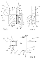
- an exhaust system 10 is shown in different views, in the transition area 20 between the exhaust duct 12 and the chimney 14 on the rear wall 22 of the chimney 14 three Helmholtz resonators 24, 24 ', 24 "are arranged side by side.
- the dimensions of the exhaust duct 12 and the chimney 14 are in turn such that that the pressure maximum of a sound mode in the transition area 20 or in the entry area 30 of the Helmholtz resonators 24, 24 ', 24 "lies.
- the three Helmholtz resonators 24, 24', 24" are formed in a cylindrical hollow body 34. Is against the flow channel 16 the hollow cylinder 34 is shielded by an upstream absorption silencer 36.
- a space 44 Spaced from this absorption muffler 36 is an intermediate wall in the hollow cylinder 34 38 arranged together with the absorption muffler 36 a space 44 includes.
- the Hollow cylinder 34 sealed gas-tight to the outside by a base 40.
- the whole Hollow cylinder 34 and the bottom 40 are thermally insulated from the outside, so that the During operation, hollow cylinder 34 assumes approximately the temperature that is in flow channel 16 prevails.
- the absorption silencer 36 has essentially the usual structure: against the Flow channel 16 is the absorption muffler 36 through a hole cover 26, the forms part of the rear wall 22 of the chimney 14.
- the hole cover 26 is backed with a flow-resistant and wear-resistant fabric 28, but acoustically is transparent, such as a metal mesh.
- a layer of damping material 46 that is adapted to the one to be absorbed Frequency range can be constructed in one or more layers.
- the material and the thickness of the Damping material 46 are determined depending on the requirement.
- a further hole cover 48 is arranged in the space 44.
- the coat of the Hollow cylinder 34 also forms the side walls for the absorption silencer 36.
- the cavity of the hollow cylinder remaining between the intermediate wall 38 and the base 40 34 is divided into three sectors by means of walls 42, which contain the volumes 25, 25 ', 25 "of the three Helmholtz resonators 24, 24 ', 24" form.
- the walls 42 close the Helmholtz resonators 24, 24 ', 24 "gas-tight against one another.
- Each Helmholtz resonator 24, 24 ', 24 " is through a tubular neck 47 which is guided through the intermediate wall 38, acoustically with that between the upstream absorption silencer 36 and the intermediate wall 38 lying space 44 connected. Low-frequency sound from the absorption silencer 36 is not absorbed, is in the space 44 and further in the three Helmholtz resonators 24, 24 ', 24 ".
- Helmholtz resonators 24, 24 ', 24 " can be changed as required. So one can Helmholtz resonator 24, two, three, four or more resonators 24, 24 ', 24 ", ... side by side be arranged.
- the shape can also vary as desired. There can be several Cylinders can be arranged side by side instead of the cylinder sectors or any other Polygon shapes. In addition, one or several Helmholtz resonators 24, 24 ', 24 ", ... can be arranged side by side.
- the three Helmholtz resonators 24, 24 ', 24 " are included With the help of necks 47 which are adjustable in length and / or in cross section, and with the help of a adjustable volume 25, 25 ', 25 "set to slightly different, low frequencies, which preferably also depends on the frequency which is damped in the intermediate space 44, differ. In this way, the low-frequency noise can be reduced with high efficiency become.
- FIG. 4 The principle of an adaptable Helmholtz resonator 24a is shown in section in FIG. 4.
- the neck 47a has two tubes 50, 52 inserted into one another. It any other cross-sectional shapes can also be selected.
- the outer tube 50 with the larger diameter is firmly anchored in the intermediate wall 30. For example, it can be welded to the intermediate wall 30.
- the outer tube 50 has on it Inside, in its two end areas each lying on circular disks, radially projections 54 extending inwards. There is a seal between the projections 54 56 arranged, which includes the inner tube 52 gas-tight with the slightly smaller diameter.
- the inner tube 52 is concentric in the outer tube 50 and against the resistance the seal 56 slidably mounted.
- the inner tube 52 points radially outwards Ends 53, which are brought into abutment with the projections 54, prevent the inner tube 52 can be pulled too far out of the outer tube 50.
- the neck 47a of the Helmholtz resonator 24a adjustable in length.
- the neck diameter can be adjusted, for example can be erected by forming the neck with a polygonal cross section and the side walls of the polygon can be moved relative to one another by means of joints.
- the volume 25a of the Helmholtz resonator 24a is adjustable in height Side walls 58 adjustable.
- the height of the side walls 58 is adjustable by means of a Floor 60 changeable.
- the displaceable bottom 60 is cup-shaped and comprises a base plate 62 and base walls 64 projecting approximately perpendicularly therefrom, which laterally encompass the side walls 58 of the Helmholtz resonator 24a.
- the Bottom plates 62 opposite end 66 the bottom walls 64 are bent radially inwards. Spaced from the bent ends 66 is a on the bottom walls 64 collar 68 extending radially inward is provided.
- a bottom seal 70 is arranged, the comprises the side walls 58 of the Helmholtz resonator 24a in a gas-tight manner.
- the sidewalls 58 have on their side facing the bottom 60 radially outwardly bent edges 72, which can be brought into abutment with the collar 68, and thus prevent the floor is removable from the side walls 58 of the Helmholtz resonator 24a.
- the volume 25a of the Helmholtz resonator 24a is thus within the scope of the displacement of the bottom 60 Stop of the bottom plate 62 on the edges 72 of the side walls 58 until the stop Edges 72 of the side walls 58 are adjustable with the collar 68 of the bottom walls 64. Consequently can the Helmholtz resonator 24a through the adjustable neck 47a and the adjustable Volume 25a can be adjusted very precisely to the frequency to be damped.
- the distance between the two tubes 54, 56 and the bottom walls 64 and the side walls 58 of the Helmholtz resonator 24a are exaggerated in FIG. 4 for the sake of clarity shown large.
Landscapes
- Engineering & Computer Science (AREA)
- Mechanical Engineering (AREA)
- General Engineering & Computer Science (AREA)
- Chemical & Material Sciences (AREA)
- Combustion & Propulsion (AREA)
- Exhaust Silencers (AREA)
- Soundproofing, Sound Blocking, And Sound Damping (AREA)
- Chimneys And Flues (AREA)
Abstract
Description
- Fig. 1
- ein erfindungsgemässes Abgassystem mit Helmholtz-Resonator;
- Fig. 2
- in einem schematischen Schnitt entlang der Längsachse des Strömungskanals einen Teil eines erfindungsgemässen Abgassystems mit nebeneinander angeordneten Helmholtz-Resonatoren;
- Fig.3
- eine Ansicht der nebeneinander angeordneten Helmholtz-Resonator aus Fig. 2 gemäss dem Schnitt III-III in Fig. 2; und
- Fig. 4
- in einem schematischen Schnitt einen Helmholtz-Resonator mit Längenverstellbarem Hals und verstellbarem Volumen.
- 10
- Abgassystems
- 12
- Abgaskanal
- 14
- Kamin
- 16
- Strömungskanal
- 18
- Abgas
- 20
- Übergangsbereich
- 22
- Rückwand
- 24, 24', 24"
- Helmholtz-Resonator
- 25, 25', 25"
- Volumen
- 26
- Lochabdeckung
- 28
- Gewebe
- 30
- Eintrittbereich
- 32
- Absorptionsschalldämpfer
- 34
- Hohlzylinder
- 36
- vorgeschalteter Absorptionsschalldämpfer
- 38
- Zwischenwand
- 40
- Boden
- 42
- Wände
- 44
- Zwischenraum
- 46
- Dämpfungsmaterial
- 48
- weitere Lochabdeckung
- 50
- Rohr aussen
- 52
- Rohr innen
- 54
- Vorsprung
- 56
- Dichtung
- 58
- Seitenwände
- 60
- verschiebbarer Boden
- 62
- Bodenplatte
- 64
- Bodenwände
- 66
- umgebogene Enden
- 68
- Kragen
- 70
- Bodendichtung
- 72
- umgebogene Ränder
Claims (11)
- Abgassystem für Industriegasturbinen mit einer Abgasleitung (12) und einem daran anschliessenden Kamin (14), welche zusammen einen durchgängigen Strömungskanal (16) bilden, und mit einer Einrichtung zur Lärmminderung, dadurch gekennzeichnet, dass zur Dämpfung der tiefen Frequenzen des Lärms ein Helmholtz-Resonator (24, 24', 24", 24a) vorgesehen ist, der mit seinem Eintrittsbereich (30) im Bereich eines Druckmaximums einer akustischen Mode angeordnet ist.
- Abgassystem nach Anspruch 1, dadurch gekennzeichnet, dass die Dimensionen des Abgaskanals (12) und des Kamins (14) so gewählt sind, dass das Druckmaximum der akustischen Mode im Übergangsbereich (20) zwischen Abgaskanal (12) und Kamin (14) auftritt.
- Abgassystem nach einem der Ansprüche 1 oder 2, dadurch gekennzeichnet, dass der Helmholtz-Resonator (24, 24', 24", 24a) im Übergangsbereich (20) zwischen Abgaskanal (12) und Kamin (14) angeordnet ist, und zwar vorzugsweise an der den Abgaskanal (12) in Strömungsrichtung (s) begrenzenden Rückwand (22) des Kamins (14).
- Abgassystem nach einem der vorgängigen Ansprüche, dadurch gekennzeichnet, dass der Helmholtz-Resonator (24, 24', 24", 24a) gegen aussen hitzeisoliert ist.
- Abgassystem nach einem der vorgängigen Ansprüche, dadurch gekennzeichnet, dass der Helmholtz-Resonator (24, 24', 24", 24a) einen Hals (47, 47a) aufweist, der in seiner Länge und/oder seinem Querschnitt verstellbar ist und/oder dass der Helmholtz-Resonator (24, 24', 24", 24a) ein Volumen (25, 25', 25,", 25a) aufweist, das verstellbar ist, und zwar vorzugsweise indem die Höhe seiner Seitenwände (58) mittels eines verschiebbaren Bodens (40, 60) verstellbar ist.
- Abgassystem nach einem der vorgängigen Ansprüche, dadurch gekennzeichnet, dass die Temperatur des Helmholtz-Resonators (24) einstellbar ist.
- Abgassystem nach einem der vorgängigen Ansprüche, dadurch gekennzeichnet, dass der Eintrittbereich (30) des Helmholtz-Resonators (24, 24', 24", 24a) akustisch transparent von der Strömung im Strömungskanal (16) abgeschirmt ist, und zwar vorzugsweise mittels eines zwischen dem Hals (47, 47a) des Helmholtz-Resonators (24, 24', 24", 24a) und der Strömung (S) angeordneten Absorptionsschalldämpfers (36).
- Abgassystem nach Anspruch 7, dadurch gekennzeichnet, dass der Absorptionsschalldämpfer (36) eine erste Lochabdeckung (26) aufweist, die vorzugsweise einen Teil einer den Strömungskanal (16) begrenzenden Wand (22) bildet, und dass er ein auf der dem Strömungskanal (16) abgewandten Seite der Lochabdeckung (26) angeordnetes, strömungsresistentes Gewebe (28), eine dem Gewebe (28) benachbarte Schicht Dämpfungsmaterial (46) und ein der ersten Lochabdeckung (26) gegenüberliegende zweite Lochabdeckung (48) sowie Seitenwände umfasst.
- Abgassystem nach Anspruch 7 oder 8, dadurch gekennzeichnet, dass zwischen dem Absorptionsschalldämpfer (36) und dem Hals (47, 47a) des Helmholtz-Resonators (24, 24', 24", 24a) ein Zwischenraum (44) angeordnet ist.
- Abgassystem nach einem der vorgängigen Ansprüche, dadurch gekennzeichnet, dass mehrere Helmholtz-Resonatoren (24, 24', 24", 24a) vorgesehen sind, die vorzugsweise auf unterschiedliche Frequenzen bzw. Moden abgestimmt sind.
- Abgassystem nach Anspruch 10, dadurch gekennzeichnet, dass die Helmholtz-Resonatoren (24, 24', 24", 24a) gasdicht voneinander getrennt sind.
Applications Claiming Priority (2)
| Application Number | Priority Date | Filing Date | Title |
|---|---|---|---|
| CH20002400 | 2000-12-08 | ||
| CH24002000 | 2000-12-08 |
Publications (3)
| Publication Number | Publication Date |
|---|---|
| EP1213538A2 true EP1213538A2 (de) | 2002-06-12 |
| EP1213538A3 EP1213538A3 (de) | 2002-07-31 |
| EP1213538B1 EP1213538B1 (de) | 2006-09-06 |
Family
ID=4569022
Family Applications (1)
| Application Number | Title | Priority Date | Filing Date |
|---|---|---|---|
| EP01811076A Expired - Lifetime EP1213538B1 (de) | 2000-12-08 | 2001-11-08 | Abgassystem mit Helmholtz-Resonator |
Country Status (3)
| Country | Link |
|---|---|
| US (1) | US6705428B2 (de) |
| EP (1) | EP1213538B1 (de) |
| DE (1) | DE50110932D1 (de) |
Cited By (4)
| Publication number | Priority date | Publication date | Assignee | Title |
|---|---|---|---|---|
| CH699322A1 (de) * | 2008-08-14 | 2010-02-15 | Alstom Technology Ltd | Verfahren zum einstellen eines helmholtz-resonators sowie helmholtz-resonator zur durchführung des verfahrens. |
| EP1865259A3 (de) * | 2006-06-09 | 2014-08-06 | Rolls-Royce Deutschland Ltd & Co KG | Gasturbinenbrennkammerwand für eine mager-brennende Gasturbinenbrennkammer |
| EP2072896A3 (de) * | 2007-12-20 | 2015-05-27 | Kutzner + Weber GmbH | Gasableitungsanordnung |
| CN105091006A (zh) * | 2014-05-15 | 2015-11-25 | 厦门嘉达声学技术有限公司 | 防雨消声风帽 |
Families Citing this family (23)
| Publication number | Priority date | Publication date | Assignee | Title |
|---|---|---|---|---|
| DE10247550A1 (de) * | 2002-10-11 | 2004-04-22 | Werner, Jürgen | Radialgebläse für Laub- und Abfallsauger, Laubbläser oder Laubladegeräte |
| US6698390B1 (en) | 2003-01-24 | 2004-03-02 | Visteon Global Technologies, Inc. | Variable tuned telescoping resonator |
| ITTO20031013A1 (it) * | 2003-12-16 | 2005-06-17 | Ansaldo Energia Spa | Sistema di smorzamento di instabilita' termoacustiche in un dispositivo combustore per una turbina a gas. |
| EP1559874B1 (de) * | 2004-02-02 | 2013-07-31 | Siemens Aktiengesellschaft | Diffusor und Turbine |
| US20060059801A1 (en) * | 2004-09-15 | 2006-03-23 | Quality Research Development & Consulting, Inc. | Acoustically intelligent structures with resonators |
| US7104243B2 (en) | 2005-02-17 | 2006-09-12 | Ford Global Technologies, Llc | Reducing acoustic noise of an engine having electromechanical valves |
| WO2007017317A1 (de) * | 2005-08-08 | 2007-02-15 | Alstom Technology Ltd | Schalldämpfer für gasturbinenanlagen |
| US7413053B2 (en) * | 2006-01-25 | 2008-08-19 | Siemens Power Generation, Inc. | Acoustic resonator with impingement cooling tubes |
| US7412889B2 (en) * | 2006-02-28 | 2008-08-19 | Caterpillar Inc. | System and method for monitoring a filter |
| US9275628B2 (en) * | 2008-05-05 | 2016-03-01 | Bonnie S. Schnitta | Tunable frequency acoustic structures |
| RU2468217C2 (ru) * | 2011-01-21 | 2012-11-27 | Закрытое акционерное общество "Концерн "Струйные технологии" | Резонансный шумоглушитель отражательного типа |
| MY174142A (en) | 2011-04-07 | 2020-03-10 | Excel Dryer Inc | Sanitizing hand dryer |
| US9421291B2 (en) | 2011-05-12 | 2016-08-23 | Fifth Third Bank | Hand dryer with sanitizing ionization assembly |
| EP2623732A1 (de) * | 2012-02-02 | 2013-08-07 | Siemens Aktiengesellschaft | Anlage und Verfahren zur Dämpfung akustischer Schwingungen bei einer entsprechenden Anlage |
| US9039352B2 (en) | 2012-11-05 | 2015-05-26 | General Electric Company | Sound attenuating chimney element for a turbomachine system |
| US9284963B2 (en) | 2013-01-28 | 2016-03-15 | American Dryer, Inc. | Blower assembly for hand dryer, with helmholtz motor mount |
| USD728859S1 (en) | 2013-04-05 | 2015-05-05 | American Dryer, Inc. | Backplate for wall mounted dryer |
| GB2516286B (en) * | 2013-07-18 | 2016-08-17 | Rolls Royce Plc | A duct and method for damping pressure waves caused by thermoacoustic instability |
| CN107166822A (zh) * | 2017-07-06 | 2017-09-15 | 中国计量大学 | 空调电子膨胀阀噪音的调节方法 |
| US10815894B2 (en) * | 2017-10-19 | 2020-10-27 | General Electric Company | Modular acoustic blocks and acoustic liners constructed therefrom |
| US10626886B2 (en) * | 2018-04-18 | 2020-04-21 | Honeywell International Inc. | Sound attenuation apparatus and methods |
| US11713904B2 (en) * | 2019-10-01 | 2023-08-01 | Johnson Controls Tyco IP Holdings LLP | Tunable sound attenuating modules |
| RU200098U1 (ru) * | 2020-01-10 | 2020-10-06 | Федеральное государственное бюджетное образовательное учреждение высшего образования "Казанский государственный энергетический университет" | Глушитель шума выбросов пара |
Citations (2)
| Publication number | Priority date | Publication date | Assignee | Title |
|---|---|---|---|---|
| DE4009072A1 (de) | 1990-03-21 | 1991-09-26 | Kaefer Isoliertechnik | Abgaskamin mit seitlicher rauchgaszufuhr |
| DE4419604A1 (de) | 1994-06-06 | 1995-12-07 | Werner Siegle | Schornsteinanordnung mit Regenauffänger |
Family Cites Families (25)
| Publication number | Priority date | Publication date | Assignee | Title |
|---|---|---|---|---|
| DE892216C (de) | 1943-03-28 | 1953-10-05 | Siemens Ag | Einrichtung zur Regelung der Spannung an den Elektroden eines Hochfrequenz-Behandlungssystems |
| US2940537A (en) | 1957-01-04 | 1960-06-14 | Gen Sound Control Inc | Means and techniques for silencing sound energy |
| US3688865A (en) | 1970-11-17 | 1972-09-05 | Cloyd D Smith | Jet engine noise suppressor |
| US3762498A (en) | 1971-07-22 | 1973-10-02 | Gen Electric | Gas turbine exhaust silencer |
| FR2152372A1 (de) * | 1971-09-08 | 1973-04-27 | Sncf | |
| US3709319A (en) | 1971-10-06 | 1973-01-09 | Gen Electric | Resonator chamber silencer for gas turbine |
| US3738448A (en) | 1971-12-13 | 1973-06-12 | Bolt Beranek & Newman | Sound silencing method and apparatus |
| US4106587A (en) | 1976-07-02 | 1978-08-15 | The United States Of America As Represented By The Administrator Of The National Aeronautics And Space Administration | Sound-suppressing structure with thermal relief |
| FR2378176A1 (fr) * | 1977-01-19 | 1978-08-18 | Bertin & Cie | Conduit insonorise, en particulier pour echappement de moteurs thermiques |
| US4371054A (en) | 1978-03-16 | 1983-02-01 | Lockheed Corporation | Flow duct sound attenuator |
| US4645032A (en) | 1985-09-05 | 1987-02-24 | The Garrett Corporation | Compact muffler apparatus and associated methods |
| SE8800867L (sv) * | 1988-03-10 | 1989-09-11 | Infrasonik Ab | Ljudreflektor |
| US5162620A (en) | 1989-11-28 | 1992-11-10 | Allied-Signal Inc. | Dual flow turbine engine muffler |
| EP0576717A1 (de) | 1992-07-03 | 1994-01-05 | Abb Research Ltd. | Gasturbinen-Brennkammer |
| US5276291A (en) | 1992-07-10 | 1994-01-04 | Norris Thomas R | Acoustic muffler for high volume fluid flow utilizing Heimholtz resonators with low flow resistance path |
| DE4330129C2 (de) | 1993-09-06 | 2002-08-29 | Bayerische Motoren Werke Ag | Abgasanlage einer Brennkraftmaschine |
| DE4414232A1 (de) * | 1994-04-23 | 1995-10-26 | Abb Management Ag | Vorrichtung zur Dämpfung von thermoakustischen Schwingungen in einer Brennkammer |
| US5644918A (en) | 1994-11-14 | 1997-07-08 | General Electric Company | Dynamics free low emissions gas turbine combustor |
| NL9500116A (nl) * | 1995-01-23 | 1996-09-02 | Fasto Nefit Bv | Geluidgedempt verbrandingssysteem, en demper bestemd voor gebruik in een dergelijk systeem. |
| CH692095A5 (de) * | 1995-03-23 | 2002-01-31 | Vaillant Gmbh | Brennstoffbeheiztes Heizgerät. |
| MX9801283A (es) * | 1995-08-17 | 1998-05-31 | Arvin Ind Inc | Atenuador de sonido con sintonizador de garganta. |
| GB9522724D0 (en) * | 1995-11-06 | 1996-01-10 | Acts Ltd | A noise attenuator for an induction system or an exhaust system |
| DE19747245C1 (de) | 1997-10-25 | 1999-04-29 | Bayerische Motoren Werke Ag | Brennkraftmaschine mit einer Abgasrückführ-Vorrichtung, insbesondere Diesel-Brennkraftmaschine |
| US6082487A (en) * | 1998-02-13 | 2000-07-04 | Donaldson Company, Inc. | Mufflers for use with engine retarders; and methods |
| EP0974788B1 (de) | 1998-07-23 | 2014-11-26 | Alstom Technology Ltd | Vorrichtung zur gezielten Schalldämpfung innerhalb einer Strömungsmaschine |
-
2001
- 2001-11-08 EP EP01811076A patent/EP1213538B1/de not_active Expired - Lifetime
- 2001-11-08 DE DE50110932T patent/DE50110932D1/de not_active Expired - Lifetime
- 2001-11-26 US US09/991,967 patent/US6705428B2/en not_active Expired - Lifetime
Patent Citations (2)
| Publication number | Priority date | Publication date | Assignee | Title |
|---|---|---|---|---|
| DE4009072A1 (de) | 1990-03-21 | 1991-09-26 | Kaefer Isoliertechnik | Abgaskamin mit seitlicher rauchgaszufuhr |
| DE4419604A1 (de) | 1994-06-06 | 1995-12-07 | Werner Siegle | Schornsteinanordnung mit Regenauffänger |
Cited By (7)
| Publication number | Priority date | Publication date | Assignee | Title |
|---|---|---|---|---|
| EP1865259A3 (de) * | 2006-06-09 | 2014-08-06 | Rolls-Royce Deutschland Ltd & Co KG | Gasturbinenbrennkammerwand für eine mager-brennende Gasturbinenbrennkammer |
| EP2072896A3 (de) * | 2007-12-20 | 2015-05-27 | Kutzner + Weber GmbH | Gasableitungsanordnung |
| CH699322A1 (de) * | 2008-08-14 | 2010-02-15 | Alstom Technology Ltd | Verfahren zum einstellen eines helmholtz-resonators sowie helmholtz-resonator zur durchführung des verfahrens. |
| WO2010018069A1 (de) | 2008-08-14 | 2010-02-18 | Alstom Technology Ltd. | Verfahren zum einstellen eines helmholtz-resonators sowie helmholtz-resonator zur durchführung des verfahrens |
| JP2011530689A (ja) * | 2008-08-14 | 2011-12-22 | アルストム テクノロジー リミテッド | ヘルムホルツ共鳴器の調節のための方法及び該方法の実施のためのヘルムホルツ共鳴器 |
| US8205714B2 (en) | 2008-08-14 | 2012-06-26 | Alstom Technology Ltd. | Method for adjusting a Helmholtz resonator and an adjustable Helmholtz resonator |
| CN105091006A (zh) * | 2014-05-15 | 2015-11-25 | 厦门嘉达声学技术有限公司 | 防雨消声风帽 |
Also Published As
| Publication number | Publication date |
|---|---|
| US20020108810A1 (en) | 2002-08-15 |
| DE50110932D1 (de) | 2006-10-19 |
| EP1213538B1 (de) | 2006-09-06 |
| EP1213538A3 (de) | 2002-07-31 |
| US6705428B2 (en) | 2004-03-16 |
Similar Documents
| Publication | Publication Date | Title |
|---|---|---|
| EP1213538B1 (de) | Abgassystem mit Helmholtz-Resonator | |
| EP0834011B2 (de) | Ansaugschalldämpfer und kraftfahrzeug | |
| EP2394033B1 (de) | Schalldämpfer mit helikalen einbauten | |
| DE2907320C2 (de) | Schalldämpfer für die Auspuffleitung einer Brennkraftmaschine | |
| DE3839242C2 (de) | Heizgerät | |
| EP1510667B1 (de) | Schalldämpfer | |
| DE69824426T2 (de) | Lärmdämpfungsgerät | |
| DE112005001089T5 (de) | Integrierte Wärmetauscher- und Schalldämpfer-Einheit | |
| DE3517859A1 (de) | Heizungskessel | |
| DE69723870T2 (de) | Vorrichtung und verfahren zur schalldämpfung in einem transportsystem für gasförmige stoffe und anwendung einer solchen vorrichtung in einem abgassystem eines schiffes | |
| DE1292667B (de) | Schalldaempfer fuer stroemende Gase | |
| DE10022240A1 (de) | Filterschalldämpfer | |
| DE2521416A1 (de) | Schallgedaempfter axialventilator | |
| EP0256416A1 (de) | Abgasreinigungsvorrichtung | |
| DE102007042869A1 (de) | Vorrichtung zur Reduzierung von Geräuschemissionen | |
| DE69401264T2 (de) | Schalldämpfer | |
| DE7307335U (de) | Abgasschalldaempfer fuer zweitakt- motore | |
| DE3406282C2 (de) | Reflexionsschalldämpfer für Brennkraftmaschinen | |
| DE3505401A1 (de) | Schalldaempfendes rohr zum uebertragen gasfoermiger medien | |
| DE19706883C2 (de) | Abgas-Schalldämpfer für Kraftfahrzeuge mit Verbrennungsmotoren | |
| DE1426202A1 (de) | Auspuff-Schalldaempfer | |
| EP1329605B1 (de) | Abgasanlage für Verbrennungsmotoren, mit einer Strömungsweiche | |
| DE10103739B4 (de) | Schalldämpfer | |
| DE602004002857T2 (de) | Schalldämpfervorrichtung | |
| DE19605540A1 (de) | Abgas-Schalldämpfer für Kraftfahrzeuge mit Verbrennungsmotoren |
Legal Events
| Date | Code | Title | Description |
|---|---|---|---|
| PUAI | Public reference made under article 153(3) epc to a published international application that has entered the european phase |
Free format text: ORIGINAL CODE: 0009012 |
|
| AK | Designated contracting states |
Kind code of ref document: A2 Designated state(s): AT BE CH CY DE DK ES FI FR GB GR IE IT LI LU MC NL PT SE TR |
|
| AX | Request for extension of the european patent |
Free format text: AL;LT;LV;MK;RO;SI |
|
| PUAL | Search report despatched |
Free format text: ORIGINAL CODE: 0009013 |
|
| AK | Designated contracting states |
Kind code of ref document: A3 Designated state(s): AT BE CH CY DE DK ES FI FR GB GR IE IT LI LU MC NL PT SE TR |
|
| AX | Request for extension of the european patent |
Free format text: AL;LT;LV;MK;RO;SI |
|
| RIC1 | Information provided on ipc code assigned before grant |
Free format text: 7F 23J 13/06 A, 7F 01D 25/30 B, 7F 23J 13/00 B |
|
| 17P | Request for examination filed |
Effective date: 20021209 |
|
| AKX | Designation fees paid |
Designated state(s): CH DE FR GB LI NL |
|
| RAP1 | Party data changed (applicant data changed or rights of an application transferred) |
Owner name: ALSTOM TECHNOLOGY LTD |
|
| GRAP | Despatch of communication of intention to grant a patent |
Free format text: ORIGINAL CODE: EPIDOSNIGR1 |
|
| GRAS | Grant fee paid |
Free format text: ORIGINAL CODE: EPIDOSNIGR3 |
|
| GRAA | (expected) grant |
Free format text: ORIGINAL CODE: 0009210 |
|
| AK | Designated contracting states |
Kind code of ref document: B1 Designated state(s): CH DE FR GB LI NL |
|
| REG | Reference to a national code |
Ref country code: GB Ref legal event code: FG4D Free format text: NOT ENGLISH |
|
| REG | Reference to a national code |
Ref country code: CH Ref legal event code: EP |
|
| REF | Corresponds to: |
Ref document number: 50110932 Country of ref document: DE Date of ref document: 20061019 Kind code of ref document: P |
|
| REG | Reference to a national code |
Ref country code: CH Ref legal event code: NV Representative=s name: ALSTOM TECHNOLOGY LTD |
|
| GBT | Gb: translation of ep patent filed (gb section 77(6)(a)/1977) |
Effective date: 20061016 |
|
| ET | Fr: translation filed | ||
| PLBE | No opposition filed within time limit |
Free format text: ORIGINAL CODE: 0009261 |
|
| STAA | Information on the status of an ep patent application or granted ep patent |
Free format text: STATUS: NO OPPOSITION FILED WITHIN TIME LIMIT |
|
| 26N | No opposition filed |
Effective date: 20070607 |
|
| REG | Reference to a national code |
Ref country code: FR Ref legal event code: PLFP Year of fee payment: 15 |
|
| REG | Reference to a national code |
Ref country code: CH Ref legal event code: PFA Owner name: GENERAL ELECTRIC TECHNOLOGY GMBH, CH Free format text: FORMER OWNER: ALSTOM TECHNOLOGY LTD, CH |
|
| REG | Reference to a national code |
Ref country code: DE Ref legal event code: R082 Ref document number: 50110932 Country of ref document: DE Representative=s name: ROESLER, UWE, DIPL.-PHYS.UNIV., DE Ref country code: DE Ref legal event code: R081 Ref document number: 50110932 Country of ref document: DE Owner name: GENERAL ELECTRIC TECHNOLOGY GMBH, CH Free format text: FORMER OWNER: ALSTOM TECHNOLOGY LTD., BADEN, CH Ref country code: DE Ref legal event code: R081 Ref document number: 50110932 Country of ref document: DE Owner name: ANSALDO ENERGIA IP UK LIMITED, GB Free format text: FORMER OWNER: ALSTOM TECHNOLOGY LTD., BADEN, CH |
|
| REG | Reference to a national code |
Ref country code: NL Ref legal event code: HC Owner name: GENERAL ELECTRIC TECHNOLOGY GMBH; CH Free format text: DETAILS ASSIGNMENT: VERANDERING VAN EIGENAAR(S), VERANDERING VAN NAAM VAN DE EIGENAAR(S); FORMER OWNER NAME: ALSTOM TECHNOLOGY LTD Effective date: 20161006 |
|
| REG | Reference to a national code |
Ref country code: FR Ref legal event code: PLFP Year of fee payment: 16 |
|
| REG | Reference to a national code |
Ref country code: FR Ref legal event code: CD Owner name: ALSTOM TECHNOLOGY LTD, CH Effective date: 20161110 |
|
| PGFP | Annual fee paid to national office [announced via postgrant information from national office to epo] |
Ref country code: CH Payment date: 20161121 Year of fee payment: 16 |
|
| REG | Reference to a national code |
Ref country code: CH Ref legal event code: PUE Owner name: ANSALDO ENERGIA IP UK LIMITED, GB Free format text: FORMER OWNER: GENERAL ELECTRIC TECHNOLOGY GMBH, CH |
|
| REG | Reference to a national code |
Ref country code: NL Ref legal event code: PD Owner name: ANSALDO ENERGIA IP UK LIMITED; GB Free format text: DETAILS ASSIGNMENT: CHANGE OF OWNER(S), ASSIGNMENT Effective date: 20170301 |
|
| REG | Reference to a national code |
Ref country code: DE Ref legal event code: R082 Ref document number: 50110932 Country of ref document: DE Representative=s name: ROESLER, UWE, DIPL.-PHYS.UNIV., DE Ref country code: DE Ref legal event code: R081 Ref document number: 50110932 Country of ref document: DE Owner name: ANSALDO ENERGIA IP UK LIMITED, GB Free format text: FORMER OWNER: GENERAL ELECTRIC TECHNOLOGY GMBH, BADEN, CH |
|
| REG | Reference to a national code |
Ref country code: GB Ref legal event code: 732E Free format text: REGISTERED BETWEEN 20170824 AND 20170830 |
|
| REG | Reference to a national code |
Ref country code: FR Ref legal event code: PLFP Year of fee payment: 17 |
|
| REG | Reference to a national code |
Ref country code: FR Ref legal event code: TP Owner name: ANSALDO ENERGIA IP UK LIMITED, GB Effective date: 20171221 |
|
| PGFP | Annual fee paid to national office [announced via postgrant information from national office to epo] |
Ref country code: FR Payment date: 20171121 Year of fee payment: 17 Ref country code: DE Payment date: 20171121 Year of fee payment: 17 Ref country code: NL Payment date: 20171120 Year of fee payment: 17 |
|
| PGFP | Annual fee paid to national office [announced via postgrant information from national office to epo] |
Ref country code: GB Payment date: 20171123 Year of fee payment: 17 |
|
| PG25 | Lapsed in a contracting state [announced via postgrant information from national office to epo] |
Ref country code: LI Free format text: LAPSE BECAUSE OF NON-PAYMENT OF DUE FEES Effective date: 20171130 Ref country code: CH Free format text: LAPSE BECAUSE OF NON-PAYMENT OF DUE FEES Effective date: 20171130 |
|
| REG | Reference to a national code |
Ref country code: DE Ref legal event code: R119 Ref document number: 50110932 Country of ref document: DE |
|
| REG | Reference to a national code |
Ref country code: NL Ref legal event code: MM Effective date: 20181201 |
|
| GBPC | Gb: european patent ceased through non-payment of renewal fee |
Effective date: 20181108 |
|
| PG25 | Lapsed in a contracting state [announced via postgrant information from national office to epo] |
Ref country code: NL Free format text: LAPSE BECAUSE OF NON-PAYMENT OF DUE FEES Effective date: 20181201 |
|
| PG25 | Lapsed in a contracting state [announced via postgrant information from national office to epo] |
Ref country code: DE Free format text: LAPSE BECAUSE OF NON-PAYMENT OF DUE FEES Effective date: 20190601 Ref country code: FR Free format text: LAPSE BECAUSE OF NON-PAYMENT OF DUE FEES Effective date: 20181130 |
|
| PG25 | Lapsed in a contracting state [announced via postgrant information from national office to epo] |
Ref country code: GB Free format text: LAPSE BECAUSE OF NON-PAYMENT OF DUE FEES Effective date: 20181108 |