EP1213387A2 - Maschine zur Herstellung einer Faserstoffbahn - Google Patents
Maschine zur Herstellung einer Faserstoffbahn Download PDFInfo
- Publication number
- EP1213387A2 EP1213387A2 EP01125604A EP01125604A EP1213387A2 EP 1213387 A2 EP1213387 A2 EP 1213387A2 EP 01125604 A EP01125604 A EP 01125604A EP 01125604 A EP01125604 A EP 01125604A EP 1213387 A2 EP1213387 A2 EP 1213387A2
- Authority
- EP
- European Patent Office
- Prior art keywords
- boundary layer
- swirler
- machine according
- air boundary
- fibrous web
- Prior art date
- Legal status (The legal status is an assumption and is not a legal conclusion. Google has not performed a legal analysis and makes no representation as to the accuracy of the status listed.)
- Withdrawn
Links
Images


Classifications
-
- D—TEXTILES; PAPER
- D21—PAPER-MAKING; PRODUCTION OF CELLULOSE
- D21G—CALENDERS; ACCESSORIES FOR PAPER-MAKING MACHINES
- D21G9/00—Other accessories for paper-making machines
-
- D—TEXTILES; PAPER
- D21—PAPER-MAKING; PRODUCTION OF CELLULOSE
- D21F—PAPER-MAKING MACHINES; METHODS OF PRODUCING PAPER THEREON
- D21F7/00—Other details of machines for making continuous webs of paper
-
- D—TEXTILES; PAPER
- D21—PAPER-MAKING; PRODUCTION OF CELLULOSE
- D21G—CALENDERS; ACCESSORIES FOR PAPER-MAKING MACHINES
- D21G7/00—Damping devices
Definitions
- the invention relates to a machine for producing a fibrous web, especially paper or cardboard web.
- the paper web can and the ligaments that support them at least in sections such as sieving, felting or the like a laminar air boundary layer train the problems with increasing speed of the web guide. These include, among others the overpressure occurring in a respective closing gap, Web flutter, swimming of the web or the belt on rollers, cylinders or the like, etc. These problems occur especially when if the web or the relevant band in a closing Gap runs in and the entrained air is displaced from the gap got to. The air must be on the side and / or against the direction of web travel be removed from the gap.
- the laminar air boundary layer is difficult to remove from the gap displace, particularly due to their high speed, the values can reach in the order of the web / belt speed, and their uniform alignment directly in the closing gap which is the least favorable of the possible orientations Case.
- the thin laminar air boundary layer can at best partially and also only reduced with considerable energy expenditure become.
- An object of the invention is therefore to provide an improved machine at the outset to create the above-mentioned kind of problems are eliminated.
- a machine for this is Production of a fibrous web, in particular paper or cardboard web, provided with at least one charging electrode and one Counterelectrode comprising electrostatic air boundary layer swirler for at least partial detachment of one on the moving fibrous web or a moving surface such as a rotating surface in particular Belt, a rotating roller or the like formed laminar air boundary layer, the moving in the direction of the fibrous web or the moving Area in front of a gap is arranged around the laminar air boundary layer detach at least partially before reaching the gap.
- an electrostatic air boundary layer swirler Under an electrostatic air boundary layer swirler is one Charging electrode and a device comprising a counter electrode to understand through which a plasma stream (electron and ion beam) is generated by electrostatic attraction to the fibrous web or the relevant moving surface is shot.
- a plasma stream electrostatic attraction to the fibrous web or the relevant moving surface is shot.
- the counter electrode can, for example, by a Roll, a cylinder or a separate electrode can be formed. there this counter electrode can in particular be grounded.
- the invention takes advantage of the fact that that generated by means of the electrostatic air boundary layer swirler turbulent flow share lighter due to its chaotic structure can suppress, which is particularly due to the fact that now give inconsistent or different flow directions and smaller velocity components in the direction of the closing gap occur.
- the aforementioned Measures with regard to the most favorable structural arrangement possible and the above-mentioned ventilation systems in particular also optimally used when dismantling the laminar air boundary layers can, as this mainly affects the turbulent flow to have.
- Eliminating or reducing disruptive Airflow is caused by partial or complete conversion the one on the fibrous web or the relevant belt (e.g. sieve, felt or the like) formed laminar air boundary layer into a turbulent Flow relieved. You get e.g. a reduction in air, for example from a sieve past an associated seal (e.g. Felt seal, Dynaseal or air knife) in the gap between for example a stabilizer and a dryer are towed, whereby in particular, a better web run possible or a reduction in Fan output is reached.
- An installation of the electrostatic Air boundary layer swirler can, for example, on the paper or the Back of the screen.
- the invention is particularly concerned take advantage of that caused by the electrostatic air boundary layer swirler generated turbulent flow has a significantly reduced inclination, getting carried away into the gap.
- the electrostatic air boundary layer swirler can in particular be carried out as described for example in WO97 / 03009 is.
- WO97 / 03009 is therefore already an electrostatic one Air boundary layer swirler known.
- This well-known electrostatic Air boundary layer swirler is however in combination with one Dryer provided. In this way, the laminar air boundary layer at various Dryer types such as IR dryers and warm air dryers the efficiency, since the heat and mass transport through the stable, laminar air boundary layer is partially shielded. A turbulent one Flow shows this resistance to a much lesser extent.
- the distance between the electrostatic air boundary layer converter and the gap a maximum of about 1000 mm, preferably in is in a range from about 100 mm to about 500 mm.
- a discharge bar is provided to at least a part of the swirled To derive air from the fibrous web or the moving surface.
- laminar air boundary layer is usually not affected because of its Thickness is generally significantly less than the technically feasible Gap between such a baffle and the fibrous web or moving surface is with the behind an electrostatic air boundary swirler arranged discharge bar just at least part of the laminar air boundary layer is removed because with this deflector at least part of the swirled air is discharged.
- the swirled This is because air is thicker than the laminar air boundary layer. As a result, the amount of air caused by the remaining Residual gap between the fibrous web or the relevant moving Surface and the discharge bar flows through, further reduced.
- a discharge bar is provided for the electrostatic air boundary layer swirler is to remove at least part of the entrained air from the fibrous web or derive the moving surface.
- the electrostatic air boundary layer swirler and / or those concerned Discharge strips are expediently again at a maximum distance of about 1000 mm in front of the gap, this distance preferably again in a range from about 100 mm to about 500 mm lies.
- a suction device is provided between the electrostatic Air boundary layer swirler and the gap to at least a portion of the swirled air to be sucked off from the fibrous web or the moving surface.
- laminar air boundary layer only slightly by suction can be reduced with high energy expenditure, one can affect turbulent flow comparatively well.
- the laminar Air boundary layer breaking up at least partially into a turbulent flow For example, electrostatic air boundary layer swirlers again at a maximum distance of about 1000 mm in front of the gap be arranged, this distance again in particular in one area can be from about 100 mm to about 500 mm. After that is with the on the fibrous web or the relevant moving surface arranged suction device the excess swirled air targeted removed, creating the desired air pressure before closing Gap can be regulated accordingly.
- the suction device is advantageously transverse to the direction of travel Sectioned fibrous web or the relevant moving surface and can be controlled and / or regulated in sections. It is therefore particularly one Zone-controlled suction possible to locally different volumes to be able to remove.
- the electrostatic air boundary layer swirler can in particular also in combination with both at least one discharge bar and one Suction device can be provided.
- a corresponding use of electrostatic air boundary layer swirlers is for example in the press section, the dryer section and / or conceivable in the area of a calender or a calender.
- the gap in question can, for example, between the fibrous web or the moving surface and a roller or a cylinder, between one that releases the fibrous web and one that decreases the fibrous web moving surface, at least one of these two moving
- An electrostatic air boundary layer swirler is assigned to surfaces can be, or between a belt delivering the fibrous web and a band that removes the fibrous web.
- the gap can, for example, also be between one which releases the fibrous web smooth moving surface, preferably a smooth roller and a die Fibrous web decreasing moving surface can be formed. In the latter Fall can decrease the moving surface, for example, by a revolving belt or a roller.
- At least one moving surface formed by a screen belt, a felt belt or the like.
- an electrostatic air boundary layer swirler arranged at a web take-off point is provided.
- the fibrous web can be in the area the delivery point e.g. be removed from a felt.
- At least one electrostatic air boundary layer swirler is provided in the area a railway take-off point with a railway issuing station and / or a web-receiving smooth roller is arranged.
- At least one electrostatic air boundary layer swirler is provided in front of a simply felted press.
- at least one electrostatic air boundary layer swirler is provided in combination with a seal associated in particular with a stabilizer or the like.
- at least one electrostatic air boundary layer swirler can be provided in combination with a seal on a stabilizer in a drying section in particular in one row.
- the seal can be filled, for example, by a felt seal, a floating sealing blade, an air knife and / or the like.
- nozzle humidifiers are used for remoistening (initial or surface) and wet profiling of fibrous webs with Water used. With increasing web speeds and decreasing Spray drop size increases the efficiency of humidification from. Modern nozzle humidifiers use two-substance nozzles with droplet diameters from about 20 ⁇ m to about 80 ⁇ m. At web speeds The efficiency is only above 1000 m / min at about 40 to about 60%. The remaining spray water quantity is with the Ambient air entrained.
- steam humidifiers are also used in smoothing units, especially in super calenders, to influence quality (gloss, Smoothness) used.
- Another object of the invention is therefore the efficiency Uniformity and application quality of nozzle humidifiers for remoistening and moisture profiling of a fibrous web in the manufacturing process to increase.
- an increase in Efficiency and especially uniformity and order quality due to nozzle moistening in the so-called "Moisture Gradient Calendaring" can be achieved.
- Another object of the invention is enhancement the efficiency of uniformity and order quality of steam humidifiers in smoothing units.
- an increase in Efficiency and uniformity of steam blow boxes in the Press section can be reached.
- a machine for this is Production of a fibrous web, in particular paper or cardboard web, provided with at least one charging electrode and one Counterelectrode comprising electrostatic air boundary layer swirler for at least partial detachment of one on the moving fibrous web formed laminar air boundary layer, which in combination with a the nozzle humidifier acting on the fibrous web is provided is to pass through the laminar air boundary layer in the direction of web travel the humidifier of the fibrous web at least caused the nozzle humidifier to partially replace.
- the mass transport is normally through the laminar one Boundary layer disturbed.
- the breakdown of the laminar air boundary layer through the use of an electrostatic air boundary layer swirler according to the invention probably increases the efficiency of the humidification over 70% for water.
- the drops are reduced Extent of kinematic disturbances (e.g. deflection of the beam direction) exposed what better uniformity of the job with brings itself. With the lower kinematic disturbances, the The risk of colliding adjacent drops is reduced, so that undesirable Large drops are avoided and the order quality is improved becomes.
- the electrostatic air boundary layer swirler is in the direction of web travel expediently arranged directly in front of the nozzle humidifier.
- the distance between the electrostatic air boundary layer swirler and the nozzle humidifier in particular smaller or be equal to 1.5 m.
- the nozzle humidifier can be used in particular with single-component nozzles / hydraulic ones Atomizing nozzles and / or two-substance nozzles / pneumatic Atomizer nozzles.
- a preferably flexible discharge bar be: This bar guides the swirled air to the remaining, gap as small as possible between the web or the relevant moving Area and the bar.
- This remaining gap can, for example are in a range of about 0.5 cm and about 2.0 cm.
- Such a bar will disturb the spray cone of the nozzles significantly reduced by the amount of air carried by the train.
- the Nozzles spray in a largely cross-flow-free environment.
- the Combination of air boundary layer swirler and deflector bar is significantly more effective than just a discharge bar, because the turbulent air layer has a larger one Thickness, i.e. Expansion in the z direction than the laminar air boundary layer having. An extraction of the swirled laminar air boundary layer may be provided.
- Nozzle humidifiers or nozzle humidifiers are sprayable for the application of all Media applicable during papermaking and finishing.
- Applications that can currently be used include rewetting and moisture profiling.
- the dry content of the fibrous web is here between about 50% and about 98%.
- Another application is that So-called moisture gradient calendaring, in which a thin, even and sprayed a film-like layer of water onto the web surface quality improvements similar to those of steam humidifiers achieve. So far, this method has failed due to the inadequate Spray quality as the required droplet sizes of about 20 ⁇ m for a film-like spray application at high web speeds the disruptive laminar air boundary layer and other air flows do not get evenly on the track.
- Use of an electrostatic air boundary layer swirler such a method can now be used.
- water is provided as the spray medium in these applications, to reduce surface tension and viscosity optionally heated or with additives such as surfactants can.
- binders may also be used as the spray medium, preferably Starch.
- Such order nozzle humidifiers are used Improving paper properties, such as printability or increasing the strength / surface strength of the paper.
- alternative can be used as a spray medium.
- the electrostatic air boundary layer swirler is in the direction of web travel preferably arranged immediately before the steam humidifier. It is the distance between the electrostatic air boundary swirler and the steam humidifier expediently less than or equal to 1.5 m.
- a machine for manufacturing a fibrous web in particular paper or cardboard web, is provided, with at least one charging electrode and one counter electrode comprehensive electrostatic air boundary layer swirler for at least partial detachment of one on the moving fibrous web formed laminar air boundary layer, which in combination with a the steam blow box acting on the fibrous web is provided is to pass through the laminar air boundary layer in the direction of web travel the steam blow box caused steam loading of the fibrous web to at least partially replace.
- the electrostatic air boundary layer swirler is in the direction of web travel preferably arranged immediately in front of the steam box. It is the distance between the electrostatic air boundary swirler and the steam box suitably less than or equal to 1.5 m.
- aspects of the invention may be behind in the direction of web travel and / or a discharge bar in front of the electrostatic air boundary layer swirler be provided to at least a part of the swirled or to remove entrained air from the fibrous web. It is between the fibrous web or the relevant moving surface and a respective one Discharge bar preferably a gap in the range of about 0.5 to leave about 2.0 cm.
- the electrostatic can be in the direction of web travel Air boundary layer swirler provided a suction device be at least a portion of the swirled air from the fibrous web suck.
- a suction device can be in the direction of web travel especially between the electrostatic air boundary swirler and a relevant discharge bar can be provided.
- the machine can be used to discharge swirled air Discharge strip in the relevant electrostatic air boundary layer swirler be integrated.
- nozzle humidifiers with at least one integrated, the discharge of at least part of the swirled air serving discharge bar conceivable.
- each one of the derivation swirling air-serving deflector for example, in one Steam humidifier or a steam blower box can be integrated.
- a respective one of the suction of at least a part of the swirled Air-serving suction device can for example in the electrostatic air boundary layer swirler, nozzle humidifier, steam humidifier, Steam box and / or the like can be integrated.
- the electrostatic air boundary layer swirler provided in combination with, for example, a humidifier or a steam blow box is provided as a separate unit from the humidifier or steam blow box.
- the deflecting strip provided behind the electrostatic air boundary layer swirler in the direction of web travel and used to discharge at least part of the swirled air is preferably arranged in front of the area in which the fibrous web is acted upon by a humidifier or steam blower box. In this way, for example, the jet streams are shielded from disturbing air currents.
- a sealing strip or the like is preferably provided in order to Prevent the escape of moisture and / or steam.
- the machine is the humidifier or the steam blower box with suction provided to extract excess air, steam and / or mist.
- suction is advantageous, among other things, if before and behind that charged by the humidifier or steam box Rail area strips are provided and / or two-substance nozzles are used become.
- a suction device can of course also be used be provided to at least a portion of the swirled air suck.
- the invention further relates to the use of an electrostatic air interface swirler in combination with a fibrous web acting nozzle humidifier. Such use is particular possible in a machine of the type specified in the claims.
- the invention further relates to the use of an electrostatic air interface swirler in combination with a fibrous web pressurizing steam humidifier. Such use is also in particular in a machine of the type specified in the claims possible.
- the invention also relates to the use of an electrostatic air interface swirler in combination with a fibrous web pressurizing steam box, including such use in particular again in a machine of the type specified in the claims Kind is possible.
- the invention also relates to the use of an electrostatic Air boundary layer swirler in combination with one behind and / or a discharge bar arranged in front of it on a fibrous web for discharge especially a part of the swirled air. This use too is in particular again in a machine in the claims specified type possible.
- the invention also relates to the use of an electrostatic Air boundary layer swirler in combination with a suction device for extracting at least part of the swirled air.
- the invention also relates to the use of one or more electrostatic air boundary layer interlacers in combination with a humidifier acting on a fibrous web, in particular nozzle and / or steam humidifier, in combination with a steam blow box acting on the fibrous web, in combination with one behind and / or one in front of it the fibrous web arranged sealing strip and / or in combination with a suction device for suctioning off at least part of the swirled air.
- a humidifier acting on a fibrous web in particular nozzle and / or steam humidifier
- a steam blow box acting on the fibrous web
- a suction device for suctioning off at least part of the swirled air.
- the invention also relates to the use of an electrostatic air boundary layer swirler in combination with a humidifier acting on a fibrous web for moisture gradient satinizing (moisture gradient calendaring).
- moisture gradient satinizing moisture gradient calendaring
- Such use is also possible in particular again in a machine of the type specified in the claims.
- the moisture gradient satin as such is described in more detail, for example, in the special print "PRACTICAL ASPECTS CONCERNING MOISTURE GRADIENT CALENDERING" by A. Heikkinen and others from “Wochenblatt für Textilfabrikation", Volume 127, 1999, No. 10, pages 680 to 685.
- PRACTICAL ASPECTS CONCERNING MOISTURE GRADIENT CALENDERING by A. Heikkinen and others from “Wochenblatt für Textilfabrikation", Volume 127, 1999, No. 10, pages 680 to 685.
- such a use can also be made in any combination with the previously mentioned types of use.
- the electrostatic air boundary layer swirlers shown in Figures 1-9 10 are each in a machine for producing a fibrous web 12 used, which is in particular a paper or Cardboard web can act.
- the electrostatic air boundary layer swirler 10 each include one Charging electrode 14 and a counter electrode, in particular grounded 16, which are formed for example by a roller or the like can.
- the electrostatic air boundary layer swirler 10 By means of the electrostatic air boundary layer swirler 10 generates a plasma stream or beam 18 (electron and ion beam), the by electrostatic attraction to the fibrous web 12 or the relevant moving surface is shot, causing the laminar air boundary layer 20 (see, for example, FIGS. 8 and 9) is disturbed in such a way that it turns into a turbulent, swirling air flow 22.
- the Plasma current 18 is between the respective charging electrode 14 and the associated counter electrode 16 generated, for example, by a Roll or a corresponding counter element can be formed.
- the respective electrostatic air boundary layer swirler 10 for example in the direction of travel L of the fibrous web 12 or the relevant moving surface be arranged in front of a gap 24 in front of the laminar air boundary layer Reaching the gap 24 at least partially detach.
- the moving surface can in particular be a rotating one Belt 26 or a rotating roller 28 act.
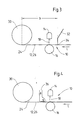
- Fig. 1 shows a schematic representation of one in a machine for production a fibrous web 12 used, arranged in front of a gap 24 electrostatic air boundary layer swirler 10, its counter electrode 16, for example, by a roller that is in particular grounded is formed.
- the counter electrode 16 with the fibrous web 12 be in contact or not.
- the gap 24 is between the fibrous web 12 or a circulating belt 26 and a roller 30 on which the fibrous web is formed 12 or the revolving belt 26 runs in the running direction L.
- the one generated by the electrostatic air boundary swirler 10 turbulent flow has a lower tendency to be carried into the gap 24 and flows better into the designated areas.
- the distance a between the electrostatic air boundary swirler 10 and the gap 24 is advantageously a maximum of about 1000 mm and is preferably in a range from 100 mm to about 500 mm.
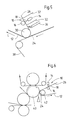
- FIG. 2 shows a schematic illustration of one comparable to that of FIG. 1 Arrangement in which the electrostatic air boundary swirler 10, however, a discharge bar 32 is connected downstream to at least one part the swirled air from the fibrous web 12 or the rotating one Derive Volume 26.
- the deflection strip 32 can, for example, by a baffle or the like may be formed.
- the swirled air has one greater thickness than the laminar air boundary layer in question. Corresponding takes the amount of air passing through the remaining gap between Fibrous web 12 or circumferential belt 26 and the discharge bar 32 flows further.
- FIG. 3 shows a schematic representation of another one with that of FIG. 1 comparable arrangement, in which the electrostatic air boundary layer swirler 10, however, a discharge bar 32 is connected upstream.
- the distance b between the discharge bar 32 and the gap 24 is advantageously a maximum of about 1000 mm and is preferably in a range of about 100 mm to about 500 mm.
- the swept strip 32 carries the entrained Air up to the remaining gap 34 between the discharge bar 32 and derived from the fibrous web 12 or the circulating belt 36.
- the subsequent electrostatic air boundary layer swirler 10 the remaining laminar air boundary layer at least partially into one turbulent flow broken up.
- the turbulent flow shows one less tendency to be entrained in the gap 24 and flows better in the designated areas.
- FIG. 4 shows a schematic representation of another one with that of FIG. 1 comparable arrangement, the electrostatic air boundary layer swirler 10, however, a suction device 36 is connected downstream.
- the electrostatic air boundary layer swirler 10 is advantageous again at a distance a (cf. FIG. 1) of a maximum of about 1000 mm from arranged in the gap 24, this distance preferably again in is in a range from about 100 mm to about 500 mm.
- the excess swirled air is removed by the suction device 36 deliberately removed, creating the desired air pressure before the closing one Gap 24 can be regulated accordingly.
- suction that can be regulated in zones is also conceivable in order to differentiate locally To be able to remove volumes.
- Fig. 5 shows a schematic representation of one used in the press section electrostatic air boundary layer swirler 10 operating in the area a web take-off point is arranged at which the fibrous web 12 of a felt 38 is removed.
- the electrostatic air boundary layer swirler 10 a revolving one taking over the fibrous web 12 Volume 26 assigned that in the area of the delivery point by one Roller 30 is guided.
- In the area of this roller 30 there is also again a gap 24 in front of which the electrostatic air interface swirler 10 is arranged.
- the one assigned to the circulating belt 26 electrostatic air boundary layer swirler 10 in the direction of L before Roller 30 and arranged accordingly in front of the gap 24.
- the electrostatic air boundary layer swirler can also be used in this case 10 optionally in combination with a downstream one and / or an upstream discharge bar 32 and / or in Combination with a downstream suction device 36 is provided his.
- the tapping point shown in FIG. 5 can, for example, after a Double felt press can be provided.
- FIG. 6 shows a schematic representation of another one in the press section used electrostatic air boundary layer swirler 10, the here, however, is arranged in the area of a web take-off point at which the fibrous web 12 is removed from a smooth roller 40.
- the electrostatic air boundary layer swirler 10 again circumferential band 26, for example a felt band, assigned by that the fibrous web 12 is taken over.
- the electrostatic air boundary layer swirler 10 is again in front of you Gap 24 arranged here between the smooth roller 40 and one Suction guide roller 42 is formed, over which the felt 26 is guided.
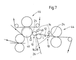
- Fig. 7 shows a schematic representation of two inserted in the press section electrostatic air boundary layer swirler 10, one of which is in the Area of a transfer roller 28 and the other in the area in front of one simply felted press 44 is arranged.
- the transfer roller 28 is between a smooth roller 40 of a preceding, also simply felted press 46 and a deflecting roller 48 arranged around which a felt 26 fed to the press 44 is guided.
- the transfer roller 28 also serves as the counter electrode 16 of the first electrostatic air boundary layer swirler 10. Its charging electrode 14 is in front of between the smooth roller 40 and the transfer roller 28 formed gap 24 arranged.
- the second is electrostatic Air boundary layer swirler 10 assigned to the felt 26 and in the direction of travel L provided in front of the gap 24 of the simply felted press 44. Are there the charging electrode 14 and the counter electrode 16 of this second one Air boundary layer swirler 10 on different sides of the felt 26 intended.
- FIG. 7 it can be in the first press for example, an extended nip press and the second press 44 in particular a roller press.
- the present can The case of the respective electrostatic air boundary layer swirler 10 optionally again in combination with a downstream and / or upstream discharge bar and / or in combination with a suction device be provided.
- Fig. 8 shows a schematic representation of one in a machine for production a fibrous web 12 in combination with a humidifier or humidifier 50 (e.g. nozzle humidifier or steam humidifier) electrostatic air boundary layer swirler 10.
- the humidifier 50 can be used, for example, for cross moisture profiling in the dryer section be provided on a dryer fabric suction roll.
- the Counter electrode 16 is formed by the relevant dryer fabric suction roll his.
- the fibrous web 12 is supported on the counter electrode 16 which preferably forms simultaneously Roller.
- the laminar air boundary layer 20 is covered with the fibrous web 12 carried along until it is from the plasma jet 18 between the charging electrode 14 and the roller forming the counter electrode 16 is swirled.
- the resulting turbulent air flow 22 can from the spray jets 52 of the humidifier 50 can be penetrated more easily.
- the turbulent air flow can further increase the efficiency optionally by a diverter bar 32 largely from the spray jets 52 of the humidifier 50 are kept away, so that this in a low-flow environment.
- the turbulent flow 22 can be reduced by a suction device 36 become.
- the humidifier 50 can in particular be a nozzle humidifier.
- a corresponding combination is also conceivable, for example, with a steam humidifier or, for example, also with a steam blow box.
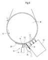
- FIG. 9 shows a schematic illustration of a further exemplary embodiment of an arrangement with an electrostatic air boundary layer swirler 10 used in combination with a humidifier 50. In particular, some of the different possible options can be seen again.
- the humidifier 50 can again be one Actuate nozzle humidifier with several nozzles 54.
- a steam humidifier or for example a steam box in combination with one electrostatic air boundary layer swirler 10 may be provided.
- the electrostatic air boundary layer swirler 10 in question comprises again a charging electrode 14 and a counter electrode 16, for example can be formed by a roller that is in particular grounded.
- the charging electrode 14 of the electrostatic air interface swirler 10 can be integrated into the humidifier 50 or as a separate one Unit may be provided.
- the laminar air boundary layer 20 is broken up, thereby creating a turbulent swirled air flow 22.
- Behind the electrostatic air boundary layer swirler 10 or its Charging electrode 14 can be a suction device 36, for example be provided to at least part of the electrostatic Extract air boundary layer swirler 10 generated turbulent air flow 22.
- a suction 56 can be provided in the humidifier 50 be, for example, excess air and excess Aspirate mist from a spray chamber 58 which, for example, between one disposed between the charging electrode 14 and the nozzles 54 Diverter 32, one at the rear end of the outlet Bar 60 arranged on the humidifier 50 and not recognizable in this FIG. 9 lateral strips can be formed.
Landscapes
- Paper (AREA)
Abstract
Description
- günstige bauliche Anordnung der verschiedenen Komponenten der Papiermaschine, um das Ausströmen der überschüssigen Luft zu erleichtern;
- lufttechnische Einrichtungen wie Saug- und Blaskästen zur Beseitigung der überschüssigen Luft (Absaugen, Luftvorhang als Abstreifer) und/oder zur Stabilisierung des Bahnlaufs;
- Leitbleche zur gezielten Abführung der überschüssigen Luft bis auf den verbleibenden Spalt zwischen Blech und Bahn bzw. Band.
Bei einer zweckmäßigen praktischen Ausführungsform der erfindungsgemäßen Maschine ist wenigstens ein elektrostatischer Luftgrenzschichtverwirbler in Kombination mit einer insbesondere einem Stabilisator oder dergleichen zugeordneten Dichtung vorgesehen. Dabei kann z.B. wenigstens ein elektrostatischer Luftgrenzschichtverwirbler in Kombination mit einer Dichtung an einem Stabilisator in einer insbesondere einreihigen Trockenpartie vorgesehen sein. Die Dichtung kann beispielsweise durch eine Filzdichtung, eine aufschwimmende Dichtklinge, ein Luftmesser und/oder dergleichen gefüllt sein.
Die in Bahnlaufrichtung hinter dem elektrostatischen Luftgrenzschichtverwirbler vorgesehene, dem Ableiten zumindest eines Teils der verwirbelten Luft dienende Ableitleiste ist vorzugsweise vor dem Bereich angeordnet, in dem die Faserstoffbahn durch einen Befeuchter oder Dampfblaskasten beaufschlagt wird. Damit wird beispielsweise eine Abschirmung der Düsenstrahlen gegen störende Luftströmungen erreicht.
Die Erfindung betrifft zudem auch die Verwendung eines elektrostatischen Luftgrenzschichtverwirblers in Kombination mit einem eine Faserstoffbahn beaufschlagenden Befeuchter bei der Feuchtigkeitsgradienten-Satinage (Moisture Gradient Calendering). Auch eine solche Verwendung ist insbesondere wieder in einer Maschine der in den Ansprüchen angegebenen Art möglich. Die Feuchtigkeitsgradienten-Satinage als solche ist beispielsweise in dem Sonderdruck "PRACTICAL ASPECTS CONCERNING MOISTURE GRADIENT CALENDERING" von A. Heikkinen u.a. aus "Wochenblatt für Papierfabrikation", Jahrgang 127, 1999, Nr. 10, Seiten 680 bis 685, näher beschrieben. Schließlich kann auch eine solche Verwendung wieder in beliebiger Kombination mit den zuvor genannten Verwendungsarten erfolgen.
- Fig. 1
- eine schematische Darstellung eines in einer Maschine zur Herstellung einer Faserstoffbahn eingesetzten, vor einem Spalt angeordneten elektrostatischen Luftgrenzschichtverwirblers,
- Fig. 2
- eine schematische Darstellung einer mit der der Fig. 1 vergleichbaren Anordnung mit einer dem elektrostatischen Luftgrenzschichtverwirbler nachgeschalteten Ableitleiste,
- Fig. 3
- eine schematische Darstellung einer mit der der Fig. 1 vergleichbaren Anordnung mit einer dem elektrostatischen Luftgrenzschichtverwirbler vorgeschalteten Ableitleiste,
- Fig. 4
- eine schematische Darstellung einer mit der der Fig. 1 vergleichbaren Anordnung mit einer dem elektrostatischen Luftgrenzschichtverwirbler nachgeschalteten Absaugeinrichtung,
- Fig. 5
- eine schematische Darstellung eines in der Pressenpartie eingesetzten elektrostatischen Luftgrenzschichtverwirblers, der im Bereich einer Bahnabnahmestelle angeordnet ist, an der die Faserstoffbahn von einem Filz abgenommen wird,
- Fig. 6
- eine schematische Darstellung eines in der Pressenpartie eingesetzten elektrostatischen Luftgrenzschichtverwirblers, der im Bereich einer Bahnabnahmestelle angeordnet ist, an der die Faserstoffbahn von einer glatten Walze abgenommen wird,
- Fig. 7
- eine schematische Darstellung zweier in der Pressenpartie eingesetzter elektrostatischer Luftgrenzschichtverwirbler, von denen einer im Bereich einer Überführungswalze und der ändere im Bereich vor einer einfach befilzten Presse angeordnet ist,
- Fig. 8
- eine schematische Darstellung eines in einer Maschine zur Herstellung einer Faserstoffbahn in Kombination mit einem Befeuchter eingesetzten elektrostatischen Luftgrenzschichtverwirblers und
- Fig. 9
- eine schematische Darstellung eines weiteren Ausführungsbeispiels einer Anordnung mit einem in Kombination mit einem Befeuchter eingesetzten elektrostatischen Luftgrenzschichtverwirblers.
Fig. 9 zeigt in schematischer Darstellung ein weiteres Ausführungsbeispiel einer Anordnung mit einem in Kombination mit einem Befeuchter 50 eingesetzten elektrostatischen Luftgrenzschichtverwirbler 10. Dabei sind insbesondere nochmals einige der verschiedenen möglichen Optionen zu erkennen.
- 10
- elektrostatischer Luftgrenzschichtverwirbler
- 12
- Faserstoffbahn
- 14
- Aufladungselektrode
- 16
- Gegenelektrode
- 18
- Plasmastrom, -strahl
- 20
- laminare Luftgrenzschicht
- 22
- turbulente, verwirbelte Luftströmung
- 24
- Spalt
- 26
- umlaufendes Band
- 28
- rotierende Walze
- 30
- Walze
- 32
- Ableitleiste
- 34
- Spalt
- 36
- Absaugeinrichtung
- 38
- Filz
- 40
- glatte Walze
- 42
- Saugleitwalze
- 44
- einfach befilzte Presse
- 46
- einfach befilzte Presse
- 48
- Umlenkwalze
- 50
- Befeuchter
- 52
- Sprühstrahlen
- 54
- Düsen
- 56
- Absaugung
- 58
- Sprühkammer
- 60
- Leiste
- a
- Abstand
- b
- Abstand
- L
- Laufrichtung
Claims (61)
dadurch gekennzeichnet, daß der Abstand (a) zwischen dem elektrostatischen Luftgrenzschichtverwirbler (10) und dem Spalt (24) maximal etwa 1000 mm beträgt und vorzugsweise in einem Bereich von etwa 100 mm bis etwa 500 mm liegt.
dadurch gekennzeichnet, daß in Laufrichtung (L) zwischen dem elektrostatischen Luftgrenzschichtverwirbler (10) und dem Spalt (24) eine Ableitleiste (32) vorgesehen ist, um zumindest einen Teil der verwirbelten Luft (22) von der Faserstoffbahn (12) bzw. der bewegten Fläche abzuleiten.
dadurch gekennzeichnet, daß in Laufrichtung (L) vor dem elektrostatischen Luftgrenzschichtverwirbler (10) eine Ableitleiste (32) vorgesehen ist, um zumindest einen Teil der mitgerissenen Luft von der Faserstoffbahn (12) bzw. der bewegten Fläche abzuleiten.
dadurch gekennzeichnet, daß zwischen dem elektrostatischen Luftgrenzschichtverwirbler (10) und dem Spalt (24) eine Absaugeinrichtung (36) vorgesehen ist, um zumindest einen Teil der verwirbelten Luft (22) von der Faserstoffbahn (12) bzw. der bewegen Fläche abzusaugen.
dadurch gekennzeichnet, daß die Absaugeinrichtung (36) quer zur Laufrichtung (L) der Faserstoffbahn (12) bzw. der betreffenden bewegten Fläche sektioniert und sektionsweise ansteuer- und/oder regelbar ist.
dadurch gekennzeichnet, daß wenigstens ein der Pressenpartie zugeordneter elektrostatischer Luftgrenzschichtverwirbler (10) vorgesehen ist.
dadurch gekennzeichnet, daß wenigstens ein der Trockenpartie zugeordneter elektrostatischer Luftgrenzschichtverwirbler (10) vorgesehen ist.
dadurch gekennzeichnet, daß der Spalt (24) zwischen der Faserstoffbahn (12) bzw. der bewegten Fläche und einer Walze (30, 40) oder einem Zylinder gebildet ist.
dadurch gekennzeichnet, daß der Spalt (24) zwischen einer die Faserstoffbahn (12) abgebenden und einer die Faserstoffbahn (12) abnehmenden bewegten Fläche gebildet und zumindest einer dieser beiden bewegten Flächen ein elektrostatischer Luftgrenzschichtverwirbler (10) zugeordnet ist.
dadurch gekennzeichnet, daß der Spalt (24) zwischen einem die Faserstoffbahn (12) abgebenden Band (38) und einem die Faserstoffbahn (12) abnehmenden Band (26) gebildet ist.
dadurch gekennzeichnet daß der Spalt (24) zwischen einer die Faserstoffbahn (12) abgebenden glatten bewegten Fläche, vorzugsweise einer glatten Walze, und einer die Faserstoffbahn (12) abnehmenden bewegten Fläche gebildet ist.
dadurch gekennzeichnet, daß bahnabnehmende bewegte Fläche durch ein umlaufendes Band (26) oder eine Walze (28) gebildet ist.
dadurch gekennzeichnet, daß zumindest eine bewegte Fläche durch ein Siebband, ein Filzband oder dergleichen gebildet ist.
dadurch gekennzeichnet, daß wenigstens ein im Bereich einer Bahnabnahmestelle angeordneter elektrostatischer Luftgrenzschichtverwirbler (10) vorgesehen ist, der ist.
dadurch gekennzeichnet, daß die Faserstoffbahn (12) im Bereich der Abnahmestelle von einem Filz (38) abgenommen wird.
dadurch gekennzeichnet, daß wenigstens ein hinter einer Doppelfilzpresse angeordneter elektrostatischer Luftgrenzschichtverwirbler (10) vorgesehen ist.
dadurch gekennzeichnet, daß wenigstens ein elektrostatischer Luftgrenzschichtverwirbler (10) vorgesehen ist, der im Bereich einer Bahnabnahmestelle mit einer bahnabgebenden und/oder einer bahnaufnehmenden glatten Walze (40 bzw. 28) angeordnet ist.
dadurch gekennzeichnet, daß wenigstens ein vor einer einfach befilzten Presse (44) angeordneter elektrostatischer Luftgrenzschichtverwirbler (10) vorgesehen ist.
dadurch gekennzeichnet, daß wenigstens ein elektrostatischer Luftgrenzschichtverwirbler (10) in Kombination mit einer insbesondere einem Stabilisator oder dergleichen zugeordneten Dichtung vorgesehen ist.
dadurch gekennzeichnet, daß wenigstens ein elektrostatischer Luftgrenzschichtverwirbler (10) in Kombination mit einer Dichtung an einem Stabilisator in einer insbesondere einreihigen Trockenpartie vorgesehen ist.
dadurch gekennzeichnet, daß die Dichtung durch eine Filzdichtung, eine aufschwimmende Dichtklinge, ein Luftmesser und/oder dergleichen gebildet ist.
dadurch gekennzeichnet, daß der elektrostatische Luftgrenzschichtverwirbler (10) in Bahnlaufrichtung (L) unmittelbar vor dem Düsenbefeuchter (50) angeordnet ist.
dadurch gekennzeichnet, daß der Abstand zwischen dem elektrostatischen Luftgrenzschichtverwirbler (10) und dem Düsenbefeuchter (50) kleiner oder gleich 1,5 m ist.
dadurch gekennzeichnet, daß der Düsenbefeuchter (50) mit Einstoffdüsen/hydraulischen Zerstäuberdüsen und/oder Zweistoffdüsen (54) /pneumatischen Zerstäuberdüsen versehen ist.
dadurch gekennzeichnet, daß der Düsenbefeuchter (50) als Auftrags-Düsenbefeuchter ausgeführt ist.
dadurch gekennzeichnet, daß der elektrostatische Luftgrenzschichtverwirbler (10) in Bahnlaufrichtung unmittelbar vor dem Dampfbefeuchter (50) angeordnet ist.
dadurch gekennzeichnet, daß der Abstand zwischen dem elektrostatischen Luftgrenzschichtverwirbler (10) und dem Dampfbefeuchter (50) kleiner oder gleich 1,5 m ist.
dadurch gekennzeichnet, daß der elektrostatische Luftgrenzschichtverwirbler (10) in Bahnlaufrichtung (L) unmittelbar vor dem Dampfblaskasten angeordnet ist.
dadurch gekennzeichnet, daß der Abstand zwischen dem elektrostatischen Luftgrenzschichtverwirbler (10) und dem Dampfblaskasten kleiner oder gleich 1,5 m ist.
dadurch gekennzeichnet, daß in Bahnlaufrichtung (L) hinter und/oder vor dem elektrostatischen Luftgrenzschichtverwirbler (10) eine Ableitleiste (32) vorgesehen ist, um zumindest einen Teil der verwirbelten bzw. mitgerissen Luft (22) von der Faserstoffbahn (12) abzuleiten.
dadurch gekennzeichnet, daß zwischen der Faserstoffbahn (12) bzw. der betreffenden bewegten Fläche und der Ableitleiste (32) ein Spalt im Bereich von etwa 0,5 bis etwa 2,0 cm belassen ist.
dadurch gekennzeichnet, daß in Bahnlaufrichtung (L) hinter dem elektrostatischen Luftgrenzschichtverwirbler (10) eine Absaugeinrichtung (36) vorgesehen ist, um zumindest einen Teil der verwirbelten Luft (22) von der Faserstoffbahn (12) abzusaugen.
dadurch gekennzeichnet, daß die Absaugeinrichtung (36) in Bahnlaufrichtung (L) zwischen dem elektrostatischen Luftgrenzschichtverwirbler (10) und einer Ableitleiste (32) vorgesehen ist.
dadurch gekennzeichnet, daß wenigstens ein in einen Düsenbefeuchter (50) integrierter elektrostatischer Luftgrenzschichtverwirbler (10) vorgesehen ist.
dadurch gekennzeichnet, daß wenigstens ein in einen Dampfbefeuchter (50) integrierter elektrostatischer Luftgrenzschichtverwirbler (10) vorgesehen ist.
dadurch gekennzeichnet, daß wenigstens ein in einen Dampfblaskasten integrierter elektrostatischer Luftgrenzschichtverwirbler (10) vorgesehen ist.
dadurch gekennzeichnet, daß der elektrostatische Luftgrenzschichtverwirbler (10) mit wenigstens einer integrierten Ableitleiste (32) versehen ist, um zumindest einen Teil der verwirbelten Luft (22) abzuleiten.
dadurch gekennzeichnet, daß der Düsenbefeuchter (50) mit wenigstens einer integrierten Ableitleiste (32) versehen ist, um zumindest einen Teil der verwirbelten Luft (22) abzuleiten.
dadurch gekennzeichnet, daß der Dampfbefeuchter (50) mit wenigstens einer integrierten Ableitleiste (32) versehen ist, um zumindest einen Teil der verwirbelten Luft (22) abzuleiten.
dadurch gekennzeichnet, daß der Dampfblaskasten mit wenigstens einer integrierten Ableitleiste (32) versehen ist, um zumindest einen Teil der verwirbelten Luft (22) abzuleiten.
dadurch gekennzeichnet, daß der elektrostatische Luftgrenzschichtverwirbler (10) mit wenigstens einer integrierten Absaugeinrichtung (36) versehen ist, um zumindest einen Teil der verwirbelten Luft (22) abzuleiten.
dadurch gekennzeichnet, daß der Düsenbefeuchter (50) mit wenigstens einer integrierten Absaugeinrichtung (36) versehen ist, um zumindest einen Teil der verwirbelten Luft (22) abzusaugen.
dadurch gekennzeichnet, daß der Dampfbefeuchter (50) mit wenigstens einer integrierten Absaugeinrichtung (36) versehen ist, um zumindest einen Teil der verwirbelten Luft (22) abzusaugen.
dadurch gekennzeichnet, daß der Dampfblaskasten mit wenigstens einer integrierten Absaugeinrichtung (36) versehen ist, um zumindest einen Teil der verwirbelten Luft (22) abzusaugen.
dadurch gekennzeichnet, daß der in Kombination mit einem Befeuchter (50) oder einem Dampfblaskasten vorgesehene elektrostatische Luftgrenzschichtverwirbler (10) als vom Befeuchter (50) bzw. Dampfblaskasten getrennte Einheit vorgesehen ist.
dadurch gekennzeichnet, daß die in Bahnlaufrichtung (L) hinter dem elektrostatischen Luftgrenzschichtverwirbler (10) vorgesehene Ableitleiste (32) vor dem Bereich angeordnet ist, in dem die Faserstoffbahn (12) durch einen Befeuchter (50) oder Dampfblaskasten beaufschlagt wird.
dadurch gekennzeichnet, daß der elektrostatischer Luftgrenzschichtverwirbler (10) in Kombination mit einem Befeuchter (50) oder einem Dampfblaskasten vorgesehen und eine Ableitleiste (32) in den elektrostatischen Luftgrenzschichtverwirbler (10) oder den Befeuchter (50) bzw. Dampfblaskasten integriert ist, um zumindest einen Teil der verwirbelten Luft (22) abzuleiten.
dadurch gekennzeichnet, daß der elektrostatische Luftgrenzschichtverwirbler (10) in Kombination mit einem Befeuchter (50) oder einem Dampfblaskasten vorgesehenen und eine von dem elektrostatischen Luftgrenzschichtverwirbler (10) und dem Befeuchter (50) bzw. dem Dampfblaskasten getrennte Ableitleiste (32) vorgesehen ist, um zumindest einen Teil der verwirbelten Luft (22) abzuleiten.
dadurch gekennzeichnet, daß im Bereich des hinteren Endes des Befeuchters (50) bzw. Dampfblaskastens eine Dichtleiste (60) oder dergleichen vorgesehen ist.
dadurch gekennzeichnet, daß der Befeuchter (50) bzw. der Dampfblaskasten mit einer Absaugung (56) versehen ist, um überschüssige Luft, Dampf und/oder Nebel abzusaugen.
Applications Claiming Priority (2)
| Application Number | Priority Date | Filing Date | Title |
|---|---|---|---|
| DE10061274 | 2000-12-08 | ||
| DE10061274A DE10061274A1 (de) | 2000-12-08 | 2000-12-08 | Maschine zur Herstellung einer Faserstoffbahn |
Publications (2)
| Publication Number | Publication Date |
|---|---|
| EP1213387A2 true EP1213387A2 (de) | 2002-06-12 |
| EP1213387A3 EP1213387A3 (de) | 2003-12-03 |
Family
ID=7666411
Family Applications (1)
| Application Number | Title | Priority Date | Filing Date |
|---|---|---|---|
| EP01125604A Withdrawn EP1213387A3 (de) | 2000-12-08 | 2001-10-26 | Maschine zur Herstellung einer Faserstoffbahn |
Country Status (3)
| Country | Link |
|---|---|
| US (1) | US20020069990A1 (de) |
| EP (1) | EP1213387A3 (de) |
| DE (1) | DE10061274A1 (de) |
Families Citing this family (10)
| Publication number | Priority date | Publication date | Assignee | Title |
|---|---|---|---|---|
| FI20021852A7 (fi) * | 2002-10-17 | 2004-04-18 | Metso Paper Inc | Rainan kireyden hallinta |
| FI119195B (fi) * | 2003-07-02 | 2008-08-29 | Metso Paper Inc | Menetelmä ja järjestely kuiturainan kostuttamiseksi |
| DE10350158A1 (de) * | 2003-10-28 | 2005-06-02 | Voith Paper Patent Gmbh | Anordnung zum Schutz einer Vorrichtung zum Aufheizen einer Faserstoffbahn |
| CA2575369A1 (en) * | 2004-07-30 | 2006-02-02 | Metso Automation Oy | Method of moistening paper web and paper web moistening device |
| US20100224122A1 (en) * | 2009-03-09 | 2010-09-09 | Illinois Tool Works Inc. | Low pressure regulation for web moistening systems |
| US9186881B2 (en) * | 2009-03-09 | 2015-11-17 | Illinois Tool Works Inc. | Thermally isolated liquid supply for web moistening |
| US20100224123A1 (en) * | 2009-03-09 | 2010-09-09 | Illinois Tool Works Inc. | Modular nozzle unit for web moistening |
| US20100224703A1 (en) * | 2009-03-09 | 2010-09-09 | Illinois Tool Works Inc. | Pneumatic Atomization Nozzle for Web Moistening |
| ITTO20120981A1 (it) * | 2012-11-13 | 2014-05-14 | Itt Italia Srl | Metodo ed impianto per la verniciatura a polvere di elementi elettricamente non conduttivi, in particolare pastiglie freno |
| US9670616B2 (en) | 2014-12-11 | 2017-06-06 | Georgia-Pacific Consumer Products Lp | Active web spreading and stabilization shower |
Family Cites Families (9)
| Publication number | Priority date | Publication date | Assignee | Title |
|---|---|---|---|---|
| FI85520C (fi) * | 1988-12-23 | 1992-04-27 | Tampella Oy Ab | Foerfarande och anordning foer ledande av en fiberbana fraon en vira genom ett pressparti. |
| DE19500752C2 (de) * | 1995-01-12 | 2000-11-30 | V I B App Bau Gmbh | Dampfbefeuchtungseinrichtung |
| DE19525453A1 (de) * | 1995-07-13 | 1997-01-16 | Eltex Elektrostatik Gmbh | Vorrichtung zum Ablösen der gasförmigen laminaren Grenzschicht |
| DE19544882C2 (de) * | 1995-12-01 | 2001-01-11 | Voith Sulzer Papiermasch Gmbh | Bahnabnahmevorrichtung |
| DE19647254A1 (de) * | 1996-11-15 | 1998-05-20 | Drytec Trocknungs Und Befeucht | Verfahren und Vorrichtung zum definierten Befeuchten von Material |
| US6500305B1 (en) * | 1998-08-08 | 2002-12-31 | V. I. B. Apparatebau Gmbh | Process and apparatus for the on-line calendering of SC-A paper |
| DE19835989C5 (de) * | 1998-08-08 | 2010-04-01 | V.I.B. Systems Gmbh | Verfahren und Vorrichtung zur Online-Kalandrierung von Papier |
| FI104645B (fi) * | 1998-08-19 | 2000-03-15 | Valmet Corp | Menetelmä ja sovitelma paperin tai kartongin ohjaamiseksi valmistuksen aikana |
| DE10052187B4 (de) * | 2000-10-20 | 2013-12-24 | Voith Patent Gmbh | Verfahren zum Glätten einer Materialbahn sowie Kalander zur Durchführung des Verfahrens |
-
2000
- 2000-12-08 DE DE10061274A patent/DE10061274A1/de not_active Withdrawn
-
2001
- 2001-10-26 EP EP01125604A patent/EP1213387A3/de not_active Withdrawn
- 2001-11-26 US US09/991,639 patent/US20020069990A1/en not_active Abandoned
Also Published As
| Publication number | Publication date |
|---|---|
| EP1213387A3 (de) | 2003-12-03 |
| US20020069990A1 (en) | 2002-06-13 |
| DE10061274A1 (de) | 2002-06-13 |
Similar Documents
| Publication | Publication Date | Title |
|---|---|---|
| DE3790947C2 (de) | Verfahren und Vorrichtung für eine Taschenventilation in der Trockenpartie einer Papiermaschine, insbesondere für schnellaufende Papiermaschinen | |
| DE69716634T3 (de) | Verfahren zur trocknung von papier und trockenpartie einer papiermaschine | |
| DE102006062235A1 (de) | Verfahren und Vorrichtung zur Trocknung einer Faserstoffbahn | |
| AT403385B (de) | Zwei-sieb-zylindertrockner | |
| EP2122049A1 (de) | Verfahren und vorrichtung zur trocknung einer faserstoffbahn | |
| DE4327601C1 (de) | Vorrichtung zum Reinigen eines umlaufenden Siebes | |
| DE3818600C2 (de) | ||
| DE29815847U1 (de) | Vorrichtung zur Online-Herstellung von Papier | |
| DE10061274A1 (de) | Maschine zur Herstellung einer Faserstoffbahn | |
| EP2217759A1 (de) | Verfahren und vorrichtung zum überführen einer papierbahn von einem stützgewebe auf ein anderes | |
| DE10024296B4 (de) | Maschine zur Herstellung einer Materialbahn | |
| DE69607924T2 (de) | Verfahren und vorrichtung zur reinigung des trockenfilz in einer papier- oder pappemaschine | |
| EP0830478A1 (de) | Vorrichtung und verfahren zur stabilisierung einer papierbahn in einer papiermaschine im bereich einer walze | |
| DE10052187B4 (de) | Verfahren zum Glätten einer Materialbahn sowie Kalander zur Durchführung des Verfahrens | |
| DE10085256B4 (de) | Verfahren zum Stützen einer Bahn und Bahnstützvorrichtung | |
| EP1540078B1 (de) | Einrichtung und verfahren zur herstellung und/oder behandlung einer faserstoffbahn | |
| DE102007021879A1 (de) | Pressenanordnung und Maschine zur Herstellung einer Faserstoffbahn | |
| EP1731665B1 (de) | Impingement-Trocknungsanordnung | |
| DE102020111197B4 (de) | Wasserstrahl-Schneideinrichtung | |
| DE102009026846A1 (de) | Verfahren zur Steuerung des Trockengehaltes einer Materialbahn, insbesondere Faserstoffbahn in einer Pressenvorrichtung und Pressenvorrichtung | |
| DE102018123380A1 (de) | Bahnkühlung | |
| DE9101248U1 (de) | Trockenpartie für Papiermaschinen | |
| DE4404726A1 (de) | Zwei-Sieb-Zylindertrockner | |
| DE19919085A1 (de) | Entwässerungsvorrichtung | |
| DE102004054886A1 (de) | Trockenpartie |
Legal Events
| Date | Code | Title | Description |
|---|---|---|---|
| PUAI | Public reference made under article 153(3) epc to a published international application that has entered the european phase |
Free format text: ORIGINAL CODE: 0009012 |
|
| AK | Designated contracting states |
Kind code of ref document: A2 Designated state(s): AT BE CH CY DE DK ES FI FR GB GR IE IT LI LU MC NL PT SE TR |
|
| AX | Request for extension of the european patent |
Free format text: AL;LT;LV;MK;RO;SI |
|
| PUAL | Search report despatched |
Free format text: ORIGINAL CODE: 0009013 |
|
| AK | Designated contracting states |
Kind code of ref document: A3 Designated state(s): AT BE CH CY DE DK ES FI FR GB GR IE IT LI LU MC NL PT SE TR |
|
| AX | Request for extension of the european patent |
Extension state: AL LT LV MK RO SI |
|
| 17P | Request for examination filed |
Effective date: 20040603 |
|
| AKX | Designation fees paid |
Designated state(s): DE FI SE |
|
| STAA | Information on the status of an ep patent application or granted ep patent |
Free format text: STATUS: THE APPLICATION IS DEEMED TO BE WITHDRAWN |
|
| 18D | Application deemed to be withdrawn |
Effective date: 20060120 |