EP1211492A1 - Anordnung zur Überwachung des Füllungsgrades einzelner Behälter in einem Lagersystem - Google Patents
Anordnung zur Überwachung des Füllungsgrades einzelner Behälter in einem Lagersystem Download PDFInfo
- Publication number
- EP1211492A1 EP1211492A1 EP01128022A EP01128022A EP1211492A1 EP 1211492 A1 EP1211492 A1 EP 1211492A1 EP 01128022 A EP01128022 A EP 01128022A EP 01128022 A EP01128022 A EP 01128022A EP 1211492 A1 EP1211492 A1 EP 1211492A1
- Authority
- EP
- European Patent Office
- Prior art keywords
- container
- support
- lever
- load
- containers
- Prior art date
- Legal status (The legal status is an assumption and is not a legal conclusion. Google has not performed a legal analysis and makes no representation as to the accuracy of the status listed.)
- Granted
Links
- 238000003860 storage Methods 0.000 title claims abstract description 12
- 238000012544 monitoring process Methods 0.000 title claims description 15
- 238000005303 weighing Methods 0.000 claims abstract description 28
- 239000007787 solid Substances 0.000 claims description 10
- 238000000034 method Methods 0.000 claims description 6
- 238000012806 monitoring device Methods 0.000 abstract 1
- 230000001960 triggered effect Effects 0.000 description 5
- 238000004519 manufacturing process Methods 0.000 description 2
- 241001136792 Alle Species 0.000 description 1
- 239000011248 coating agent Substances 0.000 description 1
- 238000000576 coating method Methods 0.000 description 1
- 238000006073 displacement reaction Methods 0.000 description 1
- 238000007689 inspection Methods 0.000 description 1
- 239000007788 liquid Substances 0.000 description 1
- 239000000463 material Substances 0.000 description 1
- 239000002184 metal Substances 0.000 description 1
- 238000011179 visual inspection Methods 0.000 description 1
Images

Classifications
-
- G—PHYSICS
- G01—MEASURING; TESTING
- G01G—WEIGHING
- G01G19/00—Weighing apparatus or methods adapted for special purposes not provided for in the preceding groups
- G01G19/40—Weighing apparatus or methods adapted for special purposes not provided for in the preceding groups with provisions for indicating, recording, or computing price or other quantities dependent on the weight
- G01G19/413—Weighing apparatus or methods adapted for special purposes not provided for in the preceding groups with provisions for indicating, recording, or computing price or other quantities dependent on the weight using electromechanical or electronic computing means
- G01G19/414—Weighing apparatus or methods adapted for special purposes not provided for in the preceding groups with provisions for indicating, recording, or computing price or other quantities dependent on the weight using electromechanical or electronic computing means using electronic computing means only
- G01G19/415—Weighing apparatus or methods adapted for special purposes not provided for in the preceding groups with provisions for indicating, recording, or computing price or other quantities dependent on the weight using electromechanical or electronic computing means using electronic computing means only combined with recording means
Definitions
- the invention relates to an arrangement of the type specified in the preamble of claim 1.
- Such arrangements for monitoring the degree of filling of individual containers in a storage system are used to ensure that a certain stock's inventory runs out in time To be able to determine the object or to enable fully automatic warehouse management. As a rule, this monitoring is carried out by visual inspection or else by complicated and expensive electronic measuring devices. Especially when it comes to the Storage of small mass parts such as screws or the like. goes, it is necessary to be effective To be able to carry out warehouse monitoring.
- the object of the invention is to provide a monitoring arrangement of the type mentioned in the introduction, which can be used in a simple and robust manner in storage systems, one accurate inventory recording should be possible despite inexpensive investments.
- the arrangement according to the invention when a minimum amount of the content is undershot one Container triggered a switching operation or a control command.
- the arrangement according to the invention is provided with a weighing system that makes it possible for each container to hold e.g. Bulk parts serves to create your own monitoring arrangement to finish one to indicate outgoing stock in good time. No complicated and prone to failure is required electronic control, but a simple weighing system, which falls below a predeterminable weight for a specific display directly on site or in one Inspection body or can directly trigger a reorder. So they're on simple way all ways for an optimal warehouse management have been opened.
- the measures according to the invention also ensure that it is immaterial whether only in one more container is removed in the front or rear area, because of the arrangement of two load levers, which are in operative connection with each other via the bracket, always only the total weight of the container and thus the container content is assumed, namely regardless of where the goods are in the container. Weight is always taken at two end regions of the container or the support surface thereof, the then possibly different loads on the two load levers via the common bracket is balanced.
- the support areas of the load levers from Essentially triangular extensions are formed in cross-section, which in groove-like depressions on the underside of the container or the support surface, on the solid surface and on each other engage opposite ends of a section of the common bracket.
- the container can also be emptied on one side to the left or right of the access page without affecting the weighing result and thus the switching process to be triggered would have an influence.
- the common bracket as an O- or C-shaped profile piece is formed, the two lever arms on opposite inner surfaces of this Profile piece are supported.
- This allows a very simple constructive design for the Balancing the weight loads on the two load levers can be created.
- the two against each other directed lever arms exert forces that act in opposite directions. It is therefore always a corresponding positive engagement of these lever arms on the bracket guaranteed.
- the bracket thus brings about a mutual comparison of the forces, thereby different Take into account the degree of filling of the containers in the front or rear area can.
- an advantageous embodiment is also to be seen in that the length the lever arms of the load lever in the area between the support on the container or the support surface for the container and the common holder in relation to the support on the ground is formed approximately in a ratio of 1: 6, the narrower ones leading to the holder Lever arms are designed much longer than the container or the bearing surface for the Container-supporting lever arms.
- the support surface for each container be used as a plate is bent at the bottom and / or bent upwards.
- the bearing surface will this gives a special stability.
- the Support surface made with a non-slip surface and / or provided with marking fields is, so that the containers can be defined on the support surface.
- this measure has nothing to do with the weighing system, because even when containers are not properly placed
- the monitoring arrangement according to the invention acts in the same way on a support surface optimal. An exact storage and thus also a security against displacement of the container is to the extent that it can be ruled out that containers with neighboring ones Contact surfaces come into active connection and would lead to faults.
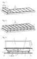
- each individual container 1 is one of the other cooperating levers formed weighing system 2 is assigned, the levers on two opposite end sections of the overlying containers 1 on the containers 1 or attack on a support surface 3 for the container 1.
- One assigned to the weighing system 2 Switching element 4 triggers when the content falls below a minimum amount (see illustration in FIG. 6) of a container 1 a switching operation or a control command.
- a minimum amount see illustration in FIG. 6
- the container 1 screws 5 5.
- the measures according to the invention can of course for any type of metallic or non-metallic mass parts or but also for any spare parts or other items that need to be kept in an orderly manner in a storage system Parts or workpieces are used.
- the measures according to the invention are suitable in same way for all possible media to be filled and stored in the container 1, so of course also for liquids.
- the weighing system 2 is essentially made up of two operatively connected to one another Load levers 6 and 7 are formed.
- One ends of these load levers 6 and 7, i.e. the two lever arms 8 and 10 support the front or rear end of a container 1 or one for supporting Containers 1 provided support surface 3.
- To form the lever arms 8 and 10 are the Load levers 6 and 7 at a distance from their support area on the container 1 or the support surface 3 on solid base 12 pivotable.
- the other two lever arms 9 and 11 of the two-armed Load levers 6 and 7 are directed towards each other, with their end sections in a common Intervene bracket 13, which creates a weight balance.
- a lever arm 11 of one Load lever 7 is extended beyond this bracket 13.
- the switching elements assigned to each container 4 are arranged in the pivoting area of this extension 14. It is therefore possible to assign such a monitoring arrangement to each individual container.
- the support areas of the load levers 6 and 7 are essentially triangular in cross section Extensions 15 to 20 formed, which in groove-like depressions on the underside of the container 1 or the support surface 3, on the solid base 12 and at opposite ends a section of the common bracket 13 engage.
- triangular in cross section Extensions can also be used with other cross-section. It only needs a support that is as friction-free and precisely aligned as possible, so that an exact Weighing function is not hindered.
- These groove-like depressions are advantageous both on the underside of the container 1 or Support surface 3 and on the solid base 12 at the free end of freely projecting support rails 21, 22, 23, 24.
- the support rails 21 to 24 and thus also the support areas of the Load levers 6 and 7 in these mutually facing sections are over a large part of the width B of a container 1 or the bearing surface 3 for a container 1, thereby optimal To provide tipping safety for the container 1.
- the constructive measure also contributes to this between the support rails 22, 24 on the base 13 and the support rails 21, 23 on the container 1 or the bearing surface 3 lying lever arm 8 or 10 of both load levers 6 and 7 via a To guide most of the width B of the container 1 or the support surface 3.
- each load lever 6 and 7 is more than five times the width C of the lever arms 9 and 11.
- Die Support rails 21 and 23, but also the support rails 22 and 24 must, as is also the case Fig. 4 can be seen, by no means over the entire width B of a container 1 or Support surface 3 be continuous.
- the extensions 15 triangular in cross section, 16, 18, 19 do not have to run continuously over the entire width A of the lever arm 8 or 10 his. All that is required is a support at an appropriate distance, so that it is safe to tip over is achieved.
- the common bracket 13 is designed as an O- or C-shaped profile piece.
- the two lever arms 9 and 11 are supported on mutually opposite inner surfaces of this profile piece are.
- the two opposing lever arms exert forces that act in opposite directions Directions work. It is therefore a non-positive attack of these lever arms 9 and 11 on the Bracket 13 guaranteed.
- the bracket 13 is in the middle between the two support rails 21 and 23 or 22 and 24 arranged so that an optimal balance of the weight load of two load levers is possible.
- the length L1 or L2 of the lever arms 8 and 9 or 10 and 11 of the load lever 6 and 7 in the range between the support on the container 1 or the support surface 3 for the container 1 and the Common bracket 13 is based on the support rails 22 and 24 for support on the ground 12 executed approximately in a ratio of 1: 6.
- the narrower leading to the bracket 13 Lever arms 9 and 11 are thus much longer than the container 1 or the support surface 3 lever arms 8 and 10 supporting the container 1.
- the extension 14 of the switch element 4 which can be brought into operative connection Lever arm 11 of a load lever 7 is a displaceable and, if necessary, fixable Balance weight 25 assigned.
- the support surface 3 for each container 1 can be a plate with down and / or up bent bends must be executed. It would also be conceivable to place between the contact surfaces 3 to use 1 webs for individual containers that move laterally to an adjacent one Support surface 3 would prevent 1 attached. Such bridges could also be easy can be arranged removably. Furthermore, the support surface 3 with a non-slip surface, for example with a corrugation or a non-slip coating, executed and / or with Marking fields may be provided, so that the container 1 can be defined on the support surface 3 are.
- relatively narrow containers 1 are mentioned, which are on correspondingly wide support surfaces 3 are supported. It would also be within the scope of the invention conceivable to provide wider containers 1, which then require more than one support surface 3 to to be able to be used. Such a container 1 is then on two or more than two contact surfaces 3 on. If the monitoring arrangement is used in this way, the weighing systems could then be used 2 two or more contact surfaces in any connection with each other in operative connection to be brought. For example, the brackets 13 of the individual weighing systems could be together be coupled. However, it would also be conceivable that each weighing system can be effectively maintained remains, since it is also guaranteed that an effective switching process is only triggered, if both or all of the switching elements 4 that are active here have been actuated.
Landscapes
- Physics & Mathematics (AREA)
- Engineering & Computer Science (AREA)
- Mathematical Physics (AREA)
- Theoretical Computer Science (AREA)
- General Physics & Mathematics (AREA)
- Details Of Rigid Or Semi-Rigid Containers (AREA)
- Basic Packing Technique (AREA)
- Warehouses Or Storage Devices (AREA)
- Automatic Analysis And Handling Materials Therefor (AREA)
Abstract
Description
Claims (11)
- Anordnung zur Überwachung des Füllungsgrades einzelner Behälter in einem Lagersystem, gekennzeichnet durch ein jedem einzelnen Behälter (1) zuzuordnendes, von miteinander zusammenwirkenden Hebeln gebildetes Wägesystem (2), wobei die Hebel an zwei einander gegenüber liegenden Endabschnitten der aufliegenden Behälter (1) an den Behältern (1) oder an einer Auflagefläche (3) für die Behälter (1) angreifen und wobei ein dem Wägesystem (2) zugeordnetes Schaltelement (4) ab einer bestimmten Menge des Inhalts eines Behälters (1) einen Schaltvorgang oder einen Steuerbefehl auslöst,
dadurch gekennzeichnet, dass das Wägesystem (2) von zwei miteinander in Wirkverbindung stehenden Lasthebeln (6, 7) gebildet ist, deren eine Enden das vordere oder hintere Ende eines Behälters (1) oder einer für die Abstützung von Behältern (1) vorgesehenen Auflagefläche (3) abstützen und zur Bildung eines Hebelarmes (8, 10) mit Abstand von diesem Abstützbereich gegenüber dem festen Untergrund (12) verschwenkbar aufliegen, dass die beiden anderen Hebelarme (9, 11) der zweiarmigen Lasthebel (6, 7) gegeneinander gerichtet sind, wobei deren Endabschnitte in eine gemeinsame Halterung (13) eingreifen, und dass ein Hebelarm (11) des einen Lasthebels (7) über diese Halterung (13) hinaus verlängert ist und das Schaltelement (4) im Verschwenkbereich dieser Verlängerung (14) angeordnet ist und bei Unterschreiten einer Mindestmenge des Inhalts eines Behälters (1) einen Schaltvorgang oder einen Steuerbefehl auslöst. - Anordnung nach Anspruch 1, dadurch gekennzeichnet, dass die Abstützbereiche der Lasthebel (6, 7) von im wesentlichen im Querschnitt dreieckigen Fortsätzen (15 bis 20) gebildet sind, welche in nutartige Vertiefungen an der Unterseite der Behälter (1) oder der Auflagefläche (3), an dem festen Untergrund (12) und an einander gegenüber liegenden Enden eines Ausschnittes der gemeinsamen Halterung (13) eingreifen.
- Anordnung nach Anspruch 2, dadurch gekennzeichnet, dass die nutartigen Vertiefungen an der Unterseite der Behälter (1) oder der Auflagefläche (3) und am festen Untergrund (12) am freien Ende von frei auskragenden Stützschienen (21 bis 24) ausgebildet sind.
- Anordnung nach Anspruch 3, dadurch gekennzeichnet, dass die Stützschienen (21 bis 24) an der Unterseite der Behälter (1) oder der Auflagefläche (3) und am festen Untergrund (12) sowie die Abstützbereiche der Lasthebel (6, 7) in diesen einander zugewandten Abschnitten über einen Grossteil der Breite (B) eines Behälters (1) oder der Auflagefläche (3) für einen Behälter (1) geführt sind.
- Anordnung nach einem der Ansprüche 1 bis 4, dadurch gekennzeichnet, dass jeweils der zwischen den Abstützschienen (21 bis 24) am Untergrund (12) und dem Abstützbereich am Behälter (1) oder der Auflagefläche (3) liegende Hebelarm (8, 10) beider Lasthebel (6, 7) über einen Grossteil der Breite (B) des Behälters (1) bzw. der Abstützfläche (3) geführt ist und die anderen, gegeneinander gerichteten Hebelarme (9,11) der beiden Lasthebel (6, 7) wesentlich schmaler ausgeführt sind.
- Anordnung nach Anspruch 5, dadurch gekennzeichnet, dass das Verhältnis der Breite (A:C) der beiden Hebelarme (8 und 9, 10 und 11) jedes Lasthebels (6, 7) grösser ist als 5:1.
- Anordnung nach einem der Ansprüche 2 bis 6, dadurch gekennzeichnet, dass die gemeinsame Halterung (13) als O- oder C-förmiges Profilstück ausgebildet ist, wobei die beiden Hebelarme (9, 11) an einander gegenüberliegenden Innenflächen dieses Profilstückes abgestützt sind.
- Anordnung nach einem der vorstehenden Ansprüche, dadurch gekennzeichnet, dass die Länge (L1, L2) der Hebelarme (8, 9, 10, 11) der Lasthebel (6, 7) im Bereich zwischen der Abstützung am Behälter (1) oder der Auflagefläche (3) für den Behälter (1) und der gemeinsamen Halterung (13) bezogen auf die Abstützung am Untergrund (12) annähernd im Verhältnis 1:6 ausgebildet ist, wobei die zur Halterung (13) führenden, schmaleren Hebelarme (9, 11) wesentlich länger ausgeführt sind als die den Behälter (1) oder die Auflagefläche (3) für den Behälter (1) abstützenden Hebelarme (8, 10).
- Anordnung nach einem der Ansprüche 1 bis 8, dadurch gekennzeichnet, dass die Auflagefläche (3) für jeweils einen Behälter (1) als Platte mit nach unten und/oder nach oben abgebogenen Abkantungen ausgeführt ist.
- Anordnung nach Anspruch 9, dadurch gekennzeichnet, dass die Auflagefläche (3) mit einer rutschfesten Oberfläche ausgeführt und/oder mit Markierungsfelder versehen ist, so dass die Behälter (1) definiert auf der Auflagefläche (3) festlegbar sind.
- Anordnung nach einem der Ansprüche 1 bis 10, dadurch gekennzeichnet, dass der mit dem Schaltelement (4) in Wirkverbindung bringbaren Verlängerung (14) des Hebelarmes (11) des einen Lasthebels (7) ein verschiebbares und gegebenenfalls festlegbares Ausgleichsgewicht (25) zugeordnet ist.
Applications Claiming Priority (2)
| Application Number | Priority Date | Filing Date | Title |
|---|---|---|---|
| DE10060147A DE10060147C1 (de) | 2000-12-04 | 2000-12-04 | Anordnung zur Überwachung des Füllungsgrades einzelner Behälter in einem Lagersystem |
| DE10060147 | 2000-12-04 |
Publications (2)
| Publication Number | Publication Date |
|---|---|
| EP1211492A1 true EP1211492A1 (de) | 2002-06-05 |
| EP1211492B1 EP1211492B1 (de) | 2008-08-06 |
Family
ID=7665690
Family Applications (1)
| Application Number | Title | Priority Date | Filing Date |
|---|---|---|---|
| EP01128022A Expired - Lifetime EP1211492B1 (de) | 2000-12-04 | 2001-11-26 | Anordnung zur Überwachung des Füllungsgrades einzelner Behälter in einem Lagersystem |
Country Status (3)
| Country | Link |
|---|---|
| EP (1) | EP1211492B1 (de) |
| AT (1) | ATE403852T1 (de) |
| DE (2) | DE10060147C1 (de) |
Families Citing this family (1)
| Publication number | Priority date | Publication date | Assignee | Title |
|---|---|---|---|---|
| DE10204104C1 (de) * | 2002-02-01 | 2003-06-05 | Sfs Handels Holding Ag Heerbru | Anordnung zur Überwachung des Füllungsgrades von einzelnen Behältern in einem Lagersystem |
Citations (4)
| Publication number | Priority date | Publication date | Assignee | Title |
|---|---|---|---|---|
| DE357273C (de) * | 1922-08-22 | Josef A Balling | Laufgewichtswaage | |
| FR544672A (fr) * | 1920-12-17 | 1922-09-26 | Bascule romaine | |
| LU39011A1 (de) * | 1960-07-28 | 1960-11-24 | ||
| EP0969272A1 (de) * | 1998-07-03 | 2000-01-05 | Bossard AG | Funkgesteuerte Lagerung und Behälter |
Family Cites Families (1)
| Publication number | Priority date | Publication date | Assignee | Title |
|---|---|---|---|---|
| US5920480A (en) * | 1997-01-10 | 1999-07-06 | Nakamura; Kaoru | Method and apparatus for detecting pallet full load state in sheet metal machining line and method and apparatus for controlling sheet metal machining line and work identifying apparatus |
-
2000
- 2000-12-04 DE DE10060147A patent/DE10060147C1/de not_active Expired - Fee Related
-
2001
- 2001-11-26 EP EP01128022A patent/EP1211492B1/de not_active Expired - Lifetime
- 2001-11-26 AT AT01128022T patent/ATE403852T1/de not_active IP Right Cessation
- 2001-11-26 DE DE50114186T patent/DE50114186D1/de not_active Expired - Fee Related
Patent Citations (4)
| Publication number | Priority date | Publication date | Assignee | Title |
|---|---|---|---|---|
| DE357273C (de) * | 1922-08-22 | Josef A Balling | Laufgewichtswaage | |
| FR544672A (fr) * | 1920-12-17 | 1922-09-26 | Bascule romaine | |
| LU39011A1 (de) * | 1960-07-28 | 1960-11-24 | ||
| EP0969272A1 (de) * | 1998-07-03 | 2000-01-05 | Bossard AG | Funkgesteuerte Lagerung und Behälter |
Also Published As
| Publication number | Publication date |
|---|---|
| ATE403852T1 (de) | 2008-08-15 |
| DE10060147C1 (de) | 2002-06-06 |
| DE50114186D1 (de) | 2008-09-18 |
| EP1211492B1 (de) | 2008-08-06 |
Similar Documents
| Publication | Publication Date | Title |
|---|---|---|
| DE4305190B4 (de) | Schubmaststapler | |
| DE3525292C1 (de) | Kabeltrommelabroller | |
| DE1161940B (de) | Schwenkbare Dachverschlussklappe fuer Fahrzeuge, insbesondere Eisenbahngueterwagen | |
| DE4039396A1 (de) | Gehaeuse fuer die aufnahme zumindest einer, insbesondere papiergeld enthaltende kassette | |
| EP1211492A1 (de) | Anordnung zur Überwachung des Füllungsgrades einzelner Behälter in einem Lagersystem | |
| DE3431498C1 (de) | Hub- und Schwenkvorrichtung fuer den Austragsabschnitt einer rohrfoermigen Schuttrutsche | |
| DE202004007109U1 (de) | Schubladenführung | |
| DE10204104C1 (de) | Anordnung zur Überwachung des Füllungsgrades von einzelnen Behältern in einem Lagersystem | |
| EP2008551B1 (de) | Lastarm zur lückenlosen Präsentation von Waren und dafür geeignete Selbstbedienungspackung | |
| DE3136334C2 (de) | Verkaufsautomat für flache Waren | |
| DE3315999C2 (de) | Auszieheinrichtung für einen mit einem Möbelkorpus versehenen Schrank | |
| DE3829719C2 (de) | ||
| DE102005017417A1 (de) | Schubladenführung | |
| DE29604799U1 (de) | Kragarmregal | |
| AT401924B (de) | Kletteraufzug | |
| DE19915781C1 (de) | Halterung zur Lagerung eines Rohrschlittens | |
| DE1190874B (de) | Rutsche | |
| DE2821101B2 (de) | Auszugführung für in einem Gestell gehaltene Schubladen o.dgl | |
| DE202018104300U1 (de) | Vorrichtung zur Abgabe einer strangförmigen Verkaufsware | |
| DE3401717C2 (de) | ||
| CH675957A5 (en) | Sliding drawer support mechanism - has chain mechanism to counter-balance overhanging weight during withdrawal | |
| DE4343280C1 (de) | Laborgerät mit Haltevorrichtung | |
| DE3514194C2 (de) | ||
| DE19501562A1 (de) | Riegelelement | |
| DE1761265A1 (de) | Vorrichtung fuer Breitstaffelkarteien |
Legal Events
| Date | Code | Title | Description |
|---|---|---|---|
| PUAI | Public reference made under article 153(3) epc to a published international application that has entered the european phase |
Free format text: ORIGINAL CODE: 0009012 |
|
| AK | Designated contracting states |
Kind code of ref document: A1 Designated state(s): AT BE CH CY DE DK ES FI FR GB GR IE IT LI LU MC NL PT SE TR |
|
| AX | Request for extension of the european patent |
Free format text: AL;LT;LV;MK;RO;SI |
|
| 17P | Request for examination filed |
Effective date: 20020628 |
|
| AKX | Designation fees paid |
Designated state(s): AT BE CH CY DE DK ES FI FR GB GR IE IT LI LU MC NL PT SE TR |
|
| 17Q | First examination report despatched |
Effective date: 20060321 |
|
| GRAP | Despatch of communication of intention to grant a patent |
Free format text: ORIGINAL CODE: EPIDOSNIGR1 |
|
| GRAS | Grant fee paid |
Free format text: ORIGINAL CODE: EPIDOSNIGR3 |
|
| GRAA | (expected) grant |
Free format text: ORIGINAL CODE: 0009210 |
|
| AK | Designated contracting states |
Kind code of ref document: B1 Designated state(s): AT BE CH CY DE DK ES FI FR GB GR IE IT LI LU MC NL PT SE TR |
|
| REG | Reference to a national code |
Ref country code: GB Ref legal event code: FG4D Free format text: NOT ENGLISH |
|
| REG | Reference to a national code |
Ref country code: CH Ref legal event code: NV Representative=s name: JUERG PLUESS SFS INTEC AG INTELLECTUAL PROPERTY MA Ref country code: CH Ref legal event code: EP |
|
| REG | Reference to a national code |
Ref country code: IE Ref legal event code: FG4D Free format text: LANGUAGE OF EP DOCUMENT: GERMAN |
|
| REF | Corresponds to: |
Ref document number: 50114186 Country of ref document: DE Date of ref document: 20080918 Kind code of ref document: P |
|
| PG25 | Lapsed in a contracting state [announced via postgrant information from national office to epo] |
Ref country code: NL Free format text: LAPSE BECAUSE OF FAILURE TO SUBMIT A TRANSLATION OF THE DESCRIPTION OR TO PAY THE FEE WITHIN THE PRESCRIBED TIME-LIMIT Effective date: 20080806 Ref country code: ES Free format text: LAPSE BECAUSE OF FAILURE TO SUBMIT A TRANSLATION OF THE DESCRIPTION OR TO PAY THE FEE WITHIN THE PRESCRIBED TIME-LIMIT Effective date: 20081117 |
|
| PGFP | Annual fee paid to national office [announced via postgrant information from national office to epo] |
Ref country code: CH Payment date: 20081001 Year of fee payment: 8 Ref country code: DE Payment date: 20081126 Year of fee payment: 8 |
|
| PG25 | Lapsed in a contracting state [announced via postgrant information from national office to epo] |
Ref country code: FI Free format text: LAPSE BECAUSE OF FAILURE TO SUBMIT A TRANSLATION OF THE DESCRIPTION OR TO PAY THE FEE WITHIN THE PRESCRIBED TIME-LIMIT Effective date: 20080806 |
|
| PGFP | Annual fee paid to national office [announced via postgrant information from national office to epo] |
Ref country code: AT Payment date: 20081114 Year of fee payment: 8 |
|
| REG | Reference to a national code |
Ref country code: IE Ref legal event code: FD4D |
|
| PGFP | Annual fee paid to national office [announced via postgrant information from national office to epo] |
Ref country code: IT Payment date: 20081125 Year of fee payment: 8 |
|
| PG25 | Lapsed in a contracting state [announced via postgrant information from national office to epo] |
Ref country code: IE Free format text: LAPSE BECAUSE OF FAILURE TO SUBMIT A TRANSLATION OF THE DESCRIPTION OR TO PAY THE FEE WITHIN THE PRESCRIBED TIME-LIMIT Effective date: 20080806 Ref country code: DK Free format text: LAPSE BECAUSE OF FAILURE TO SUBMIT A TRANSLATION OF THE DESCRIPTION OR TO PAY THE FEE WITHIN THE PRESCRIBED TIME-LIMIT Effective date: 20080806 |
|
| PGFP | Annual fee paid to national office [announced via postgrant information from national office to epo] |
Ref country code: FR Payment date: 20081128 Year of fee payment: 8 |
|
| PG25 | Lapsed in a contracting state [announced via postgrant information from national office to epo] |
Ref country code: PT Free format text: LAPSE BECAUSE OF FAILURE TO SUBMIT A TRANSLATION OF THE DESCRIPTION OR TO PAY THE FEE WITHIN THE PRESCRIBED TIME-LIMIT Effective date: 20090106 |
|
| BERE | Be: lapsed |
Owner name: SFS HANDELS HOLDING A.G. Effective date: 20081130 |
|
| PLBE | No opposition filed within time limit |
Free format text: ORIGINAL CODE: 0009261 |
|
| STAA | Information on the status of an ep patent application or granted ep patent |
Free format text: STATUS: NO OPPOSITION FILED WITHIN TIME LIMIT |
|
| PG25 | Lapsed in a contracting state [announced via postgrant information from national office to epo] |
Ref country code: MC Free format text: LAPSE BECAUSE OF NON-PAYMENT OF DUE FEES Effective date: 20081130 |
|
| 26N | No opposition filed |
Effective date: 20090507 |
|
| GBPC | Gb: european patent ceased through non-payment of renewal fee |
Effective date: 20081126 |
|
| PG25 | Lapsed in a contracting state [announced via postgrant information from national office to epo] |
Ref country code: BE Free format text: LAPSE BECAUSE OF NON-PAYMENT OF DUE FEES Effective date: 20081130 |
|
| PG25 | Lapsed in a contracting state [announced via postgrant information from national office to epo] |
Ref country code: GB Free format text: LAPSE BECAUSE OF NON-PAYMENT OF DUE FEES Effective date: 20081126 |
|
| PG25 | Lapsed in a contracting state [announced via postgrant information from national office to epo] |
Ref country code: SE Free format text: LAPSE BECAUSE OF FAILURE TO SUBMIT A TRANSLATION OF THE DESCRIPTION OR TO PAY THE FEE WITHIN THE PRESCRIBED TIME-LIMIT Effective date: 20081106 |
|
| REG | Reference to a national code |
Ref country code: CH Ref legal event code: PL |
|
| PG25 | Lapsed in a contracting state [announced via postgrant information from national office to epo] |
Ref country code: LU Free format text: LAPSE BECAUSE OF NON-PAYMENT OF DUE FEES Effective date: 20081126 Ref country code: CY Free format text: LAPSE BECAUSE OF FAILURE TO SUBMIT A TRANSLATION OF THE DESCRIPTION OR TO PAY THE FEE WITHIN THE PRESCRIBED TIME-LIMIT Effective date: 20080806 |
|
| REG | Reference to a national code |
Ref country code: FR Ref legal event code: ST Effective date: 20100730 |
|
| PG25 | Lapsed in a contracting state [announced via postgrant information from national office to epo] |
Ref country code: AT Free format text: LAPSE BECAUSE OF NON-PAYMENT OF DUE FEES Effective date: 20091126 Ref country code: TR Free format text: LAPSE BECAUSE OF FAILURE TO SUBMIT A TRANSLATION OF THE DESCRIPTION OR TO PAY THE FEE WITHIN THE PRESCRIBED TIME-LIMIT Effective date: 20080806 |
|
| PG25 | Lapsed in a contracting state [announced via postgrant information from national office to epo] |
Ref country code: LI Free format text: LAPSE BECAUSE OF NON-PAYMENT OF DUE FEES Effective date: 20091130 Ref country code: GR Free format text: LAPSE BECAUSE OF FAILURE TO SUBMIT A TRANSLATION OF THE DESCRIPTION OR TO PAY THE FEE WITHIN THE PRESCRIBED TIME-LIMIT Effective date: 20081107 Ref country code: CH Free format text: LAPSE BECAUSE OF NON-PAYMENT OF DUE FEES Effective date: 20091130 Ref country code: FR Free format text: LAPSE BECAUSE OF NON-PAYMENT OF DUE FEES Effective date: 20091130 |
|
| PG25 | Lapsed in a contracting state [announced via postgrant information from national office to epo] |
Ref country code: DE Free format text: LAPSE BECAUSE OF NON-PAYMENT OF DUE FEES Effective date: 20100601 |
|
| PG25 | Lapsed in a contracting state [announced via postgrant information from national office to epo] |
Ref country code: IT Free format text: LAPSE BECAUSE OF NON-PAYMENT OF DUE FEES Effective date: 20091126 |