EP1211114A2 - Windschott - Google Patents
Windschott Download PDFInfo
- Publication number
- EP1211114A2 EP1211114A2 EP01128201A EP01128201A EP1211114A2 EP 1211114 A2 EP1211114 A2 EP 1211114A2 EP 01128201 A EP01128201 A EP 01128201A EP 01128201 A EP01128201 A EP 01128201A EP 1211114 A2 EP1211114 A2 EP 1211114A2
- Authority
- EP
- European Patent Office
- Prior art keywords
- wind deflector
- deflector according
- carrier device
- roll bar
- carrier
- Prior art date
- Legal status (The legal status is an assumption and is not a legal conclusion. Google has not performed a legal analysis and makes no representation as to the accuracy of the status listed.)
- Granted
Links
Images


Classifications
-
- B—PERFORMING OPERATIONS; TRANSPORTING
- B60—VEHICLES IN GENERAL
- B60J—WINDOWS, WINDSCREENS, NON-FIXED ROOFS, DOORS, OR SIMILAR DEVICES FOR VEHICLES; REMOVABLE EXTERNAL PROTECTIVE COVERINGS SPECIALLY ADAPTED FOR VEHICLES
- B60J7/00—Non-fixed roofs; Roofs with movable panels, e.g. rotary sunroofs
- B60J7/22—Wind deflectors for open roofs
- B60J7/223—Wind deflectors for open roofs specially adapted for convertible cars
Definitions
- the invention relates to a wind deflector for a passenger vehicle with a roll bar, comprising wind blocker surface elements and a carrier device for the wind deflector surface elements, which can be attached to the roll bar is.
- Such a wind deflector is for example from DE 195 34 584 C1 or known from DE 196 32 352 A1.
- a wind deflector which is attached to a roll bar, serves for occupants of the passenger car sitting in front of the roll bar to protect air flowing backwards.
- the invention is based on the object of closing a wind deflector create, which can be easily fixed on a roll bar.
- This invention is invented in a wind deflector of the type mentioned at the outset solved in that the carrier device at least two in has a spaced holding tabs and that the holding tabs so are arranged and designed so that they on respective bracket sections of the Roll bar to fix the support device to the roll bar can be created.
- the carrier device can be fixed to a roll bar that is not pre-equipped needs to be.
- the roll bar does not need recesses be provided for receiving the carrier device.
- the wind deflector according to the invention can be easily attached to the retaining tabs and quickly assemble on a roll bar and again remove easily.
- the carrier device arranged at least two at a distance Has retaining tabs, it is possible to over the carrier device To hold the clamping force on the roll bar, that means it must no positive locking elements are provided for connection to the roll bar become.
- the retaining tabs are in particular rigid, and they but can have a certain elasticity, just a jamming To allow fixation (for example in the manner of a snap lock).
- a retaining tab is designed so that a corresponding bracket section can be at least partially encompassed by them is. This allows a good hold of the carrier device on a roll bar achieve and in particular via clamping force. Because the retaining tab to a certain extent can be placed around a corresponding bracket section is, this also facilitates the assembly of the carrier device, because by is an at least partially foldable retaining tab on a bracket section created a "reference position" during assembly. A tab can do this be trained so that they can grip a roll bar so far that they also over an apex of a rounded surface of the roll bar can also be placed on the roll bar. The tab is preferred designed to be elastic so that it can be pushed onto the roll bar to enable. When the tab is slid on, it forms the apex forming area of the roll bar a lock against the detachment of the Flap away from the roll bar.
- a retaining tab channel-shaped In one embodiment that is favorable in terms of production technology, there is a retaining tab channel-shaped. Since a roll bar usually has bracket elements has, which are tubular with an arranged thereon Cladding, an at least partial embracing of the Reach the bracket section through a retaining tab in a simple manner.
- a retaining tab is designed to be elastic is and in particular is resilient. It is thereby achievable that in a fixing position a clamping force can be exerted, which the carrier device attached to the roll bar. Due to the elastic training the fixing position in a simple manner with effort to elastic Achieve deformation, especially without special tools must be provided.
- a retaining tab over a wind blocker surface element level protrudes from the carrier device.
- the carrier device it is not necessary, the carrier device to the special design of the Adjust roll bar, that is, for example, to the space to adjust between two bracket elements, but the adjustment only needs to against the support device of the wind blocker.
- the at least two retaining tabs are on or nearby opposite side end of the carrier device are arranged. This allows the two outer retaining tabs to be attached to outer bracket sections create, these outer bracket sections are particularly opposite. This in turn allows a good clamping force effect to be used to determine the Reach the carrier device on the roll bar.
- the roll bar has one or more arch elements, then it is Particularly favorable if a retaining tab is arranged and designed that they are on an inner arc side of a respective bracket portion of the arch element can be created. This allows a carrier device on the arch elements clamp in a fixing position. In particular it is then very advantageous if the at least two retaining tabs on the carrier device are arranged at a distance that their surface directions opposite each other with respect to a contact surface on the roll bar point outwards. The holding forces and in particular clamping forces of the carrier device then point in the fixing position of the carrier device to the outside (away from the vehicle interior) at the respective one Outer sections of the two bracket elements opposite, so that on this way a high clamping force effect can be achieved.
- the carrier device is formed in one piece. This can be easily stored and assembled.
- the carrier device has a frame structure, in order to save weight on the one hand and on the other hand to wind deflector surface elements such as air-permeable in a simple manner windproof wind deflectors made from a net or fabric hold.
- the carrier device is designed in this way is that its length can be changed parallel to the roll bar. It can be done achieve space-saving storage of the wind deflector if the appropriate Length is minimized.
- a carrier device can be easily mount to a roll bar by holding the tabs be applied, the length is then increased by applying force until the determination position is reached and in this determination position in particular the retaining tabs on corresponding bracket sections of the roll bar and exert a force on it and acting outwards at the respective ends of the roll bar. The Carrier device is then held on the roll bar by clamping force.
- the support structure for changing the length has one or more swivel joints.
- the support structure Through one Parts of the support structure can be pivoted relative to one another and the support structure thereby has positions in which its Length is minimized (storage position or storage position) and one Position in which the length is maximized and in which the carrier device can be fixed to a roll bar by clamping force (fixing position).
- the assembly of such a support structure on a roll bar can effect quickly and easily.
- swivel joints can be opened Inexpensive way train so robust that their functionality is not impaired for a longer period of time.
- a pivot joint is advantageously at least approximately in the center arranged a frame structure of the carrier device. This allows on the one hand, in the storage position, a minimal length of the carrier device produce and on the other hand, the assembly is easier because the fixing position can be reached by symmetrical application of force.
- the fixing position beyond a dead center with respect to a pivot position is relative to a pivotable part of the carrier device.
- the locking position is for locking at least one locking element is provided, by which relative mutually movable parts of a frame structure of the carrier device are essentially immovably coupled to one another.
- the locking element blocks the swiveling movement and thus swiveling back out of the Securing position.
- the locking element is as Swing flap formed.
- Swing flap is in the fixing position via adjacent ram parts that can be pivoted relative to each other placed and couples them essentially immovably, so as to theirs to lock relative pivoting movement to each other.
- the locking element is designed as a locking slide, which also blocks the pivoting movement when it is in a locked position is.
- struts between an upper frame part and a lower frame part of the frame structure are arranged. These struts ensure transverse stability of the wind blocker across one Surface normal direction of the wind blocker surface elements.
- a support strut is used as a pivot shaft a swivel joint designed to change the length of the carrier device.
- a support strut also has the advantage that it has swivel joints couple in an upper frame part and a lower frame part can, whereby a good swivel guide can be achieved.
- support struts are arranged and designed so that they When the wind deflector is installed in the area of the bow sections of the wind deflector lie. Such support struts are then relative when the wind deflector is installed inconspicuous and therefore do not disturb the overall aesthetic impression and in particular, this increases the driver's field of vision to the rear in the interior mirror not disabled. If you look at the roll bar from one of the assembly sides side facing away from the wind deflector, then these are support struts not visible at all.
- the roll bar comprises at least a first and a second spaced arc element and the carrier device a first support structure, which on the first arch element is fixable, and a second support structure, which on a second arch element is definable. It is a separate support structure for everyone Arch element provided, wherein in the space between the Wind deflector surface elements corresponding to arch elements on the first Have the support structure and the second support structure assembled by yourself.
- a wind blocker surface element is advantageously provided by a support structure held for the associated arch element.
- the arch element itself has an opening into which an assigned support structure can be inserted is. This opening of the arch element itself can cause disruptive air currents flow from this area of the vehicle to vehicle occupants.
- the wind blocker surface element which by the corresponding support structure is held, prevents such disturbing air flows to vehicle occupants out.
- first support structure and the second support structure a support for wind deflector surface elements for the space definable between the arch elements. This will ensure the optimal function of the wind deflector guaranteed.
- the support structures then serve as holding devices for the wearer.
- the carrier is for the intermediate space disc-shaped between the arch elements, for example as Plexiglass window. This has the advantage that, on the one hand, good wind protection is reachable and secondly does not obstruct the driver's view to the rear is.
- a retaining tab is provided with a groove which is arranged and designed such that a wind blocker surface element can be inserted.
- the carrier for intermediate wind deflector surface elements can then be inserted into such grooves used against entry of air currents in the space between arch elements should protect.
- the arrangement of the groove on the tab (in one piece or relative fixed to this) then determines the position of the carrier on the roll bar.
- the groove and the associated carrier is designed so that at mounted on the roll bar support device the movability of the Carrier is limited in the direction of the vehicle interior and in particular downwards is limited.
- the wind deflector can thereby be installed in a simple manner, because the final position of the wearer is predetermined.
- a locking device is provided by which is the upper limit of the displacement of the carrier so as to To be able to securely fix the carrier to the roll bar.
- the Locking device comprise one or more locking lugs, which on the carrier are formed and in recesses on the support structures can intervene.
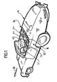
- FIG. 2 An embodiment of a wind deflector according to the invention, which in Figure 2 shown and there designated as a whole with 10, is on one in Figures 1 and 2 as a whole with 12 designated roll bar
- Motor vehicle body 14 of a passenger vehicle can be determined.
- Passenger motor vehicle is preferably a convertible vehicle.
- the roll bar 12 stands over a belt line or parapet line 16 the vehicle body 14 upward and includes two at a distance Arch elements 18 and 20 arranged in relation to one another. These are next to one another each behind backrests 22 and 24 arranged in a passenger compartment 26 Sitting the convertible vehicle arranged.
- the arch elements 18 and 20 are in one variant of an embodiment basically the same design, for example in the form of a U-bend, whose leg opening points down towards the convertible vehicle. They extend in a plane transverse to a longitudinal direction 28 of the motor vehicle body 14.
- An arch element 18, 20 comprises a first arch section 30 in the shape of a middle leg, on the left and right in each case a second arch section 32 and a third arch section 34 in the Shape of side legs connects.
- the side legs 32 and 34 in turn are connected to a base support 36 of the roll bar 12.
- the basic carrier 36 runs between the arch elements 18 and 20 (this is shown in FIG Figure 2 not shown). In the variant shown in Figures 1 and 2 runs the base support 36 also between the side legs 32 and 34, that is, the U-shaped arch elements 18, 20 are in the shown Variant taking into account the basic support D-shaped.
- the arch elements 18, 20 are provided with a cladding 38.
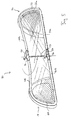
- a first exemplary embodiment of a wind deflector 10, which is shown in FIG Whole is denoted by 40, a carrier device 42, which on the roll bar 12 can be fixed, and which wind blocker surface elements 44 holds.
- the carrier device 42 comprises a frame structure 46 with upper ones Frame parts 48a, 48b and lower frame parts 50a, 50b.
- At the Roll bar 12 mounted support device 42 are the lower frame parts 50a, 50b facing the base support 36 of the roll bar 12.
- a side bracket 52a, 52b is arranged between the associated upper frame part 48a and lower frame part 50a or 48b, 50b.
- the upper frame parts 48a and 48b are connected via a swivel joint 54 Pivot axis transverse to the upper frame parts 48a, 48b relative to one another pivotable.
- the swivel joint 54 is preferably essentially arranged centrally on the frame structure 46.
- a Swivel joint 56 is provided, by means of which the lower frame parts 50a and 50b are pivotable relative to one another, the pivot joints 54 and 56 are arranged and aligned with respect to each other so that they are a common one Have pivot axis.
- a length of the carrier device can be 42 related to the plane in which the arch elements 18, 20 of the roll bar 12 lie, change. This change in length is accompanied by a change the depth dimension of the carrier device 42 transversely to said one Level: If the depth extension is minimal, then the length of the carrier device 42 in the above-mentioned level and vice versa.
- the locking element 58 is designed as a swivel flap, which is arranged on the upper frame part 48b and pivotable with a Pivot axis transverse to the upper frame part 48b and transverse to the pivot axis of the swivel joint 54 is mounted.
- the flap is channel-shaped with the channel opening facing downwards and this is adapted to an outer surface of the upper frame part 48a in the region of the swivel joint 54
- the flap 58 projects parallel to the upper frame part 48b upper frame part 48b and can if the upper frame parts 48a and 48b aligned at least in the area of the swivel joint 54 are on the surface of the upper frame part 48a. This is the The upper frame parts 48a, 48b can be pivoted back relative to one another and by means of the latching element 58 is therefore a fixing position 60 ( Figure 3) of the carrier device 42 lockable.
- This setting position 60 corresponds essentially to a position in which the carrier 42 a maximum length with respect to the plane in which the arch elements 18 and 20 have.
- the fixing position 60 defined by a dead center of the pivotability of the upper frame parts 48a and 48b relative to each other, in which an end face 62a of the upper frame part 48a to an end face 62b of the upper Frame part 48b abuts and thus a further pivotability of the upper Frame parts 48a and 48b are locked relative to each other.
- the lower frame part 50b is also provided with a locking element 64, which is basically designed and arranged the same as with reference the upper frame parts 48a and 48b for the locking element 58 described.
- the locking element 64 on the lower Frame part 50a is arranged.
- Holding tab 66a, 66b arranged, which are each formed channel-shaped with a gutter opening that faces outwards.
- the retaining tabs 66a, 66b are respectively to the second arc sections 32 of the arc elements 18 and 20 adapted in shape so that a retaining tab 66a or 66b an inside of the second arch section 32 of the associated arch element 18 or 20 can be applied and partially the associated arch element 18, 20 can engage around the second arc section 32.
- the retaining tabs 66a, 66b made of an elastic material manufactured so that they have a spring action, in particular the carrier device 42 via the retaining tabs 66a, 66b on the roll bar 12 can be clamped.
- FIG. 2 In the embodiment shown in Figure 2 is left and right, respectively from the pivot joint 54 at a distance from this and preferably symmetrical to the pivot axis between the upper frame part 48a and the lower frame part 50a a support strut 68a and between the upper frame part 48b and the lower frame part 50b a support strut 68b arranged.
- the support struts 68a and 68b connect the upper frame parts 48a, 48b with the lower frame parts 50a, 50b and thereby increase the Cross stability of the carrier device.
- the wind blocker surface elements 44 are in particular by a wind deflector track 70 formed, which is preferably made of a flexible material web is made, which in turn from an air-permeable, but for Windproof net or fabric is formed.
- This wind deflector track 70 is arranged and formed on the carrier device 42 so that they have the pivotability of the frame parts 48a, 48b and 50a, 50b relative not hindered each other and on the other hand with the mounted carrier device 42 is essentially tensioned in the fixing position 60.
- a first wind deflector track 72a is stretched and between the upper frame part 48b and the lower frame part 50b, a second wind deflector track 72b is tensioned, wherein the two wind deflector webs 72a and 72b have mesh directions, which in the area of the pivot axis of the pivot joints 54, 56 in one Angles meet.
- the wind deflector tracks 72a and 72b are in the area 74 in which they meet, woven together.
- the material of the wind deflector web 72a and 72b elastic so as not to hinder the relative pivotability of the frame structure 46.
- the wind deflector according to the invention works as follows:
- the wind deflector 40 can be stored in a space-saving manner in which the frame structure 46 is pivoted so that the upper frame parts 48a and 48b are facing each other and aligned substantially parallel to each other are.
- the length of the carrier device 42 is then essentially that Reduces half of its maximum length and the depth of the carrier 42 to essentially double their minimum depth.
- the Frame structure 46 unfolded and in particular expanded so far that the Retaining tabs 66a and 66b are located on the inside of the second arc sections 32 let the respective arch elements 18 and 20 create.
- the frame parts 48a, 48b and 50a, 50b then become further relative to one another with the application of force pivoted until the fixing position 60 is reached.
- the retaining tabs 66a and 66b are formed from an elastic material, they practice in the fixing position 60 a force on the assigned second arc sections 32 of the respective arch elements 18 and 20, this force is directed outwards.
- the carrier device 42 and thus the wind blocker As a result, as shown in FIG. 3, 40 is held in a clamped manner on the roll bar 12.
- wind deflector 40 By clamping the wind deflector 40 on the roll bar 12 must the latter cannot be or will not be prepared for holding a wind deflector.
- the wind deflector 40 can also be easily attached to the roll bar 12 assemble and remove itself in a simple way by the above mentioned steps are carried out in the opposite direction. Also lets store the wind deflector 40 to save space.
- the wind deflector 40 is on the roll bar 12 on its side facing away from the passenger compartment 26. Thereby the wind deflector 40 is not in the passenger compartment 26, which creates the risk of injury is reduced in the event of accidents.
- the wind deflector according to the invention can, however, on each side the roll bar 12.
- FIG whole A variant of the wind blocker 40 according to FIG. 2 and FIG. 3 is shown in FIG whole designated 76.
- This wind blocker 76 is basically of the same design, like the wind deflector 40 and works like this. Same Elements are therefore designated with the same reference symbols.
- the wind blocker 76 differs from the wind blocker 44 in that a support strut 78a which between the upper frame part 48a and is arranged lower frame part 50a, is arcuate and in its shape is adapted to the third arch section 34 of the arch element 20. Furthermore, the support strut 78a is arranged so that when assembled Carrier device 42 lies in the region of the arch element 20. The arch element 20 then covers the support strut 78a.
- the support strut 78b is similar arranged between the upper frame part 48b and the lower frame part 50b and trained.
- a support strut 82 through a pivot shaft between the pivot joint 54 and the swivel joint 56, that is to say the swivel joint 54 on the upper frame parts 48a, 48b and the swivel joint 56 on the lower frame parts 50a and 50b are supported on one another. Otherwise the wind deflector 80 functions as described above.
- a slider 84 can also be provided, which in a groove 86a of the upper frame part 48a and in a groove 86b of the upper Frame part 48b is guided.
- a slide 84 is particularly in the Frame structure 46 can be integrated in such a way that it is not noticeable and so the aesthetic Overall impression is not disturbed by locking elements.
- the grooves 86a and 86b are arranged so that they are in the fixing position 60th are aligned with each other so that the slide from an upper Frame part, for example the upper frame part 48b, into the other frame part, for example, be moved from the upper frame part 48a can, the slide then lying partly in the groove 86a and partly in the groove 86b and thus a further pivoting of the upper frame parts 48a and 48b is locked, that is, the fixing position 60 is locked.
- the slide 84 is in particular captively guided in the groove 86b and such that it can be fully immersed in the pivoting movements not to hinder before reaching the definition position 60.
- the lower frame parts 50a and 50b can also be made in the same way lock together.
- Fixing position beyond a dead center of the pivoting movement of the Frame structure 46 lies.
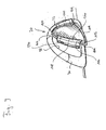
- a wind deflector according to the invention which is designated as a whole in FIG. 7 with 88 comprises one as a whole with 90 designated a first support structure 92, which can be fixed to the arch element 20, and a second support structure 94, which can be fixed on the arch element 18.
- the first support structure 92 and the second carrier structure 94 are fundamentally the same, but mirror-symmetrical trained to each other. The following is therefore only the first Support structure 92 described in more detail.
- the first support structure 92 is corresponding to the Adjusted arc sections 30, 32 and 34 of the arc element 20, namely on the inside ( Figure 9).
- the first carrier structure 92 has one Frame 100 with a middle leg 102, side legs 104 and 106 and a connecting leg 108 between the side legs 104 and 106 on.
- the wind deflector track 96 is located on these legs 102, 104, 106 and 108 held.
- the first support structure 92 with its legs is designed that the opening 98 is substantially completely covered.
- a holding tab 110 is arranged, which is basically the same as the above in connection with the Holding tab 66a described in the first embodiment.
- the holding tab 110 serves to apply the first support structure 92 to an inside of the second Arc section 32, which arc section 32 an outside of the Convertible vehicle is facing.
- a holding tab 112 On the side leg 104 of the first support structure 92 is a holding tab 112 arranged, which has a trough-shaped element 114, which for Serves on an inside of the third arc section 34, this third arc section 34 facing the interior of the convertible vehicle is.
- the holding tab 112 is in particular at least in the region of the channel-shaped Elements 114 made of an elastic material so that the first support structure can be attached to the arch element 20 by means of the holding tab 110 is and the groove-shaped element for applying the retaining tab 112 114 can be deformed elastically such that the blocking by the third Arch section 34 can be overcome and then the first support structure 92 is held clamped on the arch element 20.
- tolerance compensation can also be made, for example, in relation to manufacturing tolerances achieve.
- the retaining tab 112 has one that is connected to it in one piece Groove element 116, which when the first support structure is inserted 92 is arranged facing the other arch element 18 and thereby offset to the level of the arch elements 18, 20.
- a groove 118 of the groove element 116 runs transversely to a distance direction between the Arch elements 18 and 20.
- a carrier 120 can be inserted into this groove 118, which wind blocker surface element 122 carries or a wind blocker surface element itself represents.
- a corresponding groove 124 of the second carrier structure 94 is in this case when this second support structure 94 is inserted into the arch element 18, the groove 118 facing.
- the carrier 120 can then be in the space between insert the arch elements 18 and 20 into the grooves 118 and 124.
- the structure is 120 and the grooves 118 and 124 are so formed such that a downward displacement of the carrier 120 is limited; the carrier 120 is movable downwards, the base carrier 36 the roll bar 12 to, fixable, in particular by a stop, which by the interaction between the carrier 120 when it is inserted into the grooves 118 and 124, is formed with these grooves.
- the grooves 118 and 124 are formed in an arc shape based on the first support structure 92 and the second support structure 94 arranged mirror-symmetrically to each other.
- the carrier 120 is at its end End faces 126, 128 are also arcuate in shape such that a lower face 130 is shorter than an upper face 132. This allows the carrier 120 in the on the arch elements 18th or 20 fixed grooves 124 or 118 and move downwards, however, from a certain position the movability is limited.
- the grooves 118, 124 are, for example provided with recesses 134 (FIG. 9), into the latching lugs, of the carrier 120 can snap into place.
- Other locking means can also be provided such as positive locking means for fixing the carrier 120 to the carrier structures 92, 94.
- the carrier 120 can in particular by a disc such as be formed of a plexiglass pane. But it can also be a frame structure be provided with a wind deflector fixed to it.
- a support structure 92, 94 can in particular be in the form of a one-piece plastic injection molded part be formed, the associated wind blocker surface element is formed in one piece on this injection molded part (it is then no mesh or fabric provided as a wind blocker surface element).
- the wind blocker is therefore 88 in three parts: the first support structure 92 is provided for the arch element 20, the second support structure 94 for the arch element 18 and the support 120, which is held by the two support structures 92 and 94, for the Gap between the arch elements 18 and 20.
- a carrier device is provided with tabs which the arch elements 18, 20 on their respective at least partially embrace the opposite outer sides.
- the support structure for a wind blocker surface element between the arch elements 18 and 20 is then separate from the support structures for the respective wind blocker surface elements for the arch elements 18, 20.
- the wind deflector 88 according to the invention can be attached to the roll bar as follows Set 12:
- the holding tab of a carrier structure for example the holding tab 110 of the second support structure 94, is on the inside of the second arc section 32 of the arch element 18 and the second support structure 94 is then turned towards the third arc section 34 (FIG. 8).
- the retaining tab on the third arc section 34 can be fixed by being elastically deformed and then, after overcoming the lock, the elastic deformation is released and afterwards the second support structure 94 is held clamped on the arch element 18.
- a support structure is not held clamped to an arch element, but only abuts and the final fixation takes place only via the structure 120.
- the first Carrier structure 92 proceeded. Thereafter, the grooves 118 are the first support structure 92 and 124 of the second support structure 94 are aligned with one another in a plane parallel to the plane of the arch elements 18 and 20.
- the carrier 120 can then be used for the wind blocker surface elements be used.
- the carrier 120 prevents rotating the support structures 92 and 94 away from the support structure 120, so that after insertion in grooves 118 and 124 the final fixation of the carrier device 90 on the roll bar 12.
Abstract
Description
- Figur 1
- eine perspektivische Ansicht eines Personenkraftfahrzeuges mit einem Überrollbügel, an welchem das erfindungsgemäße Windschott festlegbar ist;
- Figur 2
- ein erstes Ausführungsbeispiel eines Windschottes vor der Montage an einem Überrollbügel;
- Figur 3
- das Windschott gemäß Figur 2 nach Montage an dem Überrollbügel;
- Figur 4
- eine Variante des Windschottes gemäß Figur 3;
- Figur 5
- eine weitere Variante einer Ausführungsform eines Windschottes;
- Figur 6
- eine schematische Ansicht einer Verriegelungsvorrichtung zur Festlegung eines erfindungsgemäßen Windschottes an einem Überrollbügel;
- Figur 7
- ein zweites Ausführungsbeispiel eines Windschottes in perspektivischer Ansicht, wobei das Windschott an einem Überrollbügel montiert ist;
- Figur 8
- eine schematische Darstellung bezüglich der Montage des Windschottes gemäß Figur 7 und
- Figur 9
- eine Trägerstruktur des Windschottes gemäß Figur 7 vor der endgültigen Montage an einem Bügelelement eines Überrollbügels.
Claims (32)
- Windschott für ein Personenkraftfahrzeug mit Überrollbügel (12), umfassend Windschott-Flächenelemente (70; 122) und eine Trägervorrichtung (42; 90) für die Windschott-Flächenelemente (70; 120), welche an dem Überrollbügel (12) festlegbar ist, dadurch gekennzeichnet, daß die Trägervorrichtung (42; 90) mindestens zwei in einem Abstand angeordnete Haltelaschen (66a, 66b; 110, 112) aufweist und daß die Haltelaschen (66a, 66b; 110, 112) so angeordnet und ausgebildet sind, daß sie an jeweiligen Bügelabschnitten (32; 34) des Überrollbügels (12) zur Festlegung der Trägervorrichtung (42; 90) an den Überrollbügel (12) anlegbar sind.
- Windschott nach Anspruch 1, dadurch gekennzeichnet, daß eine Haltelasche (66a, 66b; 110, 112) so ausgebildet ist, daß ein korrespondierender Bügelabschnitt (32; 34) durch sie mindestens teilweise umgreifbar ist.
- Windschott nach Anspruch 1 oder 2, dadurch gekennzeichnet, daß eine Haltelasche (66a, 66b; 110, 112) an die Abmessungen des Bügelabschnittes (32; 34), an welchen sie angelegt werden soll, in ihrer Form angepaßt ist.
- Windschott nach einem der vorangehenden Ansprüche, dadurch gekennzeichnet, daß eine Haltelasche (66a, 66b; 110, 112) rinnenförmig ausgebildet ist.
- Windschott nach einem der vorangehenden Ansprüche, dadurch gekennzeichnet, daß eine Haltelasche (66a, 66b; 110, 112) elastisch ausgebildet ist.
- Windschott nach einem der vorangehenden Ansprüche, dadurch gekennzeichnet, daß eine Haltelasche (66a, 66b; 110, 112) über eine Windschott-Flächenelement-Ebene der Trägervorrichtung (42; 90) hinausragt.
- Windschott nach einem der vorangehenden Ansprüche, dadurch gekennzeichnet, daß die mindestens zwei Haltelaschen (66a, 66b; 110, 112) an oder in der Nähe gegenüberliegender seitlicher Enden der Trägervorrichtung (42; 90) angeordnet sind.
- Windschott nach einem der vorangehenden Ansprüche, dadurch gekennzeichnet, daß der Überrollbügel ein oder mehrere Bogenelemente (18, 20) aufweist und daß eine Haltelasche (66a, 66b; 110, 112) so angeordnet und ausgebildet ist, daß sie an einer Innenbogenseite eines jeweiligen Bügelabschnittes (32; 34) des Bogenelementes (18, 20) anlegbar ist.
- Windschott nach Anspruch 8, dadurch gekennzeichnet, daß die mindestens zwei Haltelaschen (66a, 66b; 110, 112) so an der Trägervorrichtung (42; 90) in einem Abstand angeordnet sind, daß sie in ihrer Flächennormalen-Richtung bezüglich einer Anlagefläche an dem Überrollbügel (12) jeweils entgegengerichtet nach außen weisen.
- Windschott nach einem der vorangehenden Ansprüche, dadurch gekennzeichnet, daß die Trägervorrichtung (42) einteilig ausgebildet ist.
- Windschott nach Anspruch 10, dadurch gekennzeichnet, daß die Trägervorrichtung (42) eine Rahmenstruktur (46) aufweist.
- Windschott nach Anspruch 10 oder 11, dadurch gekennzeichnet, daß die Trägervorrichtung (42) so ausgebildet ist, daß ihre Länge parallel zum Überrollbügel (12) veränderbar ist.
- Windschott nach Anspruch 12, dadurch gekennzeichnet, daß die Trägervorrichtung (42) zur Längenänderung ein oder mehrere Schwenkgelenke (54, 56) aufweist.
- Windschott nach Anspruch 13, dadurch gekennzeichnet, daß ein Schwenkgelenk (54; 56) zumindest näherungsweise mittig an einer Rahmenstruktur (46) der Trägervorrichtung (42) angeordnet ist.
- Windschott nach einem der Ansprüche 10 bis 14, dadurch gekennzeichnet, daß in einer Festlegungsstellung (60) der Trägervorrichtung (42) diese mittels der mindestens zwei Haltelaschen (66a, 66b) an dem Überrollbügel (12) klemmend festlegbar ist.
- Windschott nach Anspruch 15, dadurch gekennzeichnet, daß die Festlegungsstellung (60) jenseits eines Totpunktes bezüglich Schwenkpositionen relativ zueinander schwenkbarer Rahmenteile (48a, 48b; 50a, 50b) der Trägervorrichtung (42) liegt.
- Windschott nach Anspruch 15 oder 16, dadurch gekennzeichnet, daß die Festlegungsstellung verriegelbar ist.
- Windschott nach Anspruch 17, dadurch gekennzeichnet, daß zur Verriegelung der Festlegungsposition (60) mindestens ein Rastelement (58; 64) vorgesehen ist, durch welches relativ zueinander bewegliche Teile (48a, 48b; 50a, 50b) einer Rahmenstruktur (46) der Trägervorrichtung (42) miteinander im wesentlichen unbeweglich koppelbar sind.
- Windschott nach Anspruch 18, dadurch gekennzeichnet, daß das Rastelement als Schwenkklappe (58) ausgebildet ist.
- Windschott nach Anspruch 18, dadurch gekennzeichnet, daß das Rastelement als Rastschieber (84) ausgebildet ist.
- Windschott nach einem der Ansprüche 11 bis 18, dadurch gekennzeichnet, daß eine oder mehrere Streben (68a, 68b; 78a, 78b; 82) zwischen einem oberen Rahmenteil (48a; 48b) und einem unteren Rahmenteil (50a; 50b) der Rahmenstruktur (46) angeordnet sind.
- Windschott nach Anspruch 21, dadurch gekennzeichnet, daß eine Stützstrebe (82) als Schwenkwelle eines Schwenkgelenks (54; 56) zur Längenänderung der Trägervorrichtung (42) ausgebildet ist.
- Windschott nach Anspruch 21 oder 22, dadurch gekennzeichnet, daß Stützstreben (78a, 78b) so angeordnet und ausgebildet sind, daß sie bei montiertem Windschott (10) im Bereich von Bogenabschnitten (34) des Windschottes (10) liegen.
- Windschott nach einem der Ansprüche 1 bis 9, dadurch gekennzeichnet, daß der Überrollbügel (12) mindestens eine erstes und ein zweites beabstandetes Bogenelement (18, 20) umfaßt und daß die Trägervorrichtung (90) eine erste Trägerstruktur (92), welche an dem ersten Bogenelement (20) festlegbar ist, und eine zweite Trägerstruktur (94), welche an dem zweiten Bogenelement (18) festlegbar ist, umfaßt.
- Windschott nach Anspruch 24, dadurch gekennzeichnet, daß durch eine Trägerstruktur (92; 94) ein Windschott-Flächenelement (96) für das zugeordnete Bogenelement (20; 18) gehalten ist.
- Windschott nach Anspruch 24 oder 25, dadurch gekennzeichnet, daß zwischen der ersten Trägerstruktur (92) und der zweiten Trägerstruktur (94) ein Träger (120) für Windschott-Flächenelemente (122) für den Zwischenraum zwischen den Bogenelementen (18, 20) festlegbar sind.
- Windschott nach Anspruch 26, dadurch gekennzeichnet, daß das Windschott-Flächenelement (122) für den Zwischenraum zwischen den Bogenelementen (18, 20) scheibenförmig ausgebildet ist.
- Windschott nach einem der Ansprüche 24 bis 27, dadurch gekennzeichnet, daß eine Trägerstruktur (92; 94) gegenüberliegende Haltelaschen (110, 112) zu deren Festlegung an dem zugeordneten Bogenelement (20; 18) aufweist.
- Windschott nach Anspruch 28, dadurch gekennzeichnet, daß eine Haltelasche (112) mit einer Nut (118) versehen ist, welches so angeordnet und ausgebildet ist, daß ein Träger (120) für Windschott-Flächenelemente (122) einschiebbar ist.
- Windschott nach Anspruch 29, dadurch gekennzeichnet, daß die Nut (118) und der zugeordnete Träger (120) so ausgebildet sind, daß bei an dem Überrollbügel (12) montierter Trägervorrichtung die Verschieblichkeit des Trägers (120) nach unten begrenzt ist.
- Windschott nach einem der Ansprüche 26 bis 30, dadurch gekennzeichnet, daß eine Verriegelungsvorrichtung vorgesehen ist, durch welche eine Verschiebung eines montierten Trägers (120) nach oben begrenzbar ist.
- Windschott nach einem der Ansprüche 26 bis 31, dadurch gekennzeichnet, daß die Trägerstrukturen (92, 94) und der Träger (120) so ausgebildet sind und so an dem Überrollbügel (12) montierbar sind, daß die zugeordneten Windschott-Flächenelemente (96, 122) bündig in einer Fläche liegen.
Applications Claiming Priority (2)
| Application Number | Priority Date | Filing Date | Title |
|---|---|---|---|
| DE10061562A DE10061562A1 (de) | 2000-12-04 | 2000-12-04 | Windschott |
| DE10061562 | 2000-12-04 |
Publications (3)
| Publication Number | Publication Date |
|---|---|
| EP1211114A2 true EP1211114A2 (de) | 2002-06-05 |
| EP1211114A3 EP1211114A3 (de) | 2003-05-07 |
| EP1211114B1 EP1211114B1 (de) | 2007-05-23 |
Family
ID=7666622
Family Applications (1)
| Application Number | Title | Priority Date | Filing Date |
|---|---|---|---|
| EP01128201A Expired - Lifetime EP1211114B1 (de) | 2000-12-04 | 2001-11-28 | Windschott |
Country Status (3)
| Country | Link |
|---|---|
| US (2) | US6557928B2 (de) |
| EP (1) | EP1211114B1 (de) |
| DE (2) | DE10061562A1 (de) |
Cited By (2)
| Publication number | Priority date | Publication date | Assignee | Title |
|---|---|---|---|---|
| WO2008056138A1 (en) * | 2006-11-07 | 2008-05-15 | Aston Martin Lagonda Limited | Rear net wind deflector for a convertible vehicle |
| EP2614976A1 (de) * | 2012-01-16 | 2013-07-17 | iKON Fahrzeug Design und Engineering GbR | Windschotteinrichtung für ein Cabriolet-Fahrzeug |
Families Citing this family (23)
| Publication number | Priority date | Publication date | Assignee | Title |
|---|---|---|---|---|
| GB0122815D0 (en) * | 2001-09-21 | 2001-11-14 | Bridport Aviat Products Ltd | A cargo barrier |
| US6695373B1 (en) * | 2002-07-11 | 2004-02-24 | Karen Meise | Transparent auto headrest |
| DE10311837B3 (de) * | 2003-03-18 | 2004-07-01 | Dr.Ing.H.C. F. Porsche Ag | Windschott für ein Cabriolet |
| US6962382B2 (en) * | 2003-05-23 | 2005-11-08 | David Scarlett | Barrier system |
| DE10341989A1 (de) * | 2003-09-09 | 2005-04-21 | Oris Fahrzeugteile Riehle H | Cabriofahrzeug |
| WO2005080105A2 (en) * | 2004-02-17 | 2005-09-01 | Wilhelm Karmann Gmbh | Windscreen deflector for automotive vehicles |
| DE102004037482A1 (de) * | 2004-07-27 | 2006-02-16 | Oris Fahrzeugteile Hans Riehle Gmbh | Windstopeinrichtung |
| DE102004061758B4 (de) * | 2004-12-22 | 2015-08-13 | Volkswagen Ag | Windstopeinrichtung |
| FR2892073B1 (fr) * | 2005-10-19 | 2009-07-03 | Heuliez Sa | Dispositif a filet anti-remous |
| DE102005054185B4 (de) * | 2005-11-14 | 2008-08-28 | Webasto Ag | Windabweiser im Kraftfahrzeugbereich |
| US20080001428A1 (en) * | 2006-06-28 | 2008-01-03 | Hans Pehrson | Foldable wind breaker |
| DE102006043626A1 (de) * | 2006-09-12 | 2008-03-27 | Scambia Industrial Developments Aktiengesellschaft | Windstopeinrichtung |
| US20090021051A1 (en) * | 2007-07-20 | 2009-01-22 | Brown Steve H | Window assembly for a utility terrain vehicle |
| DE102008047734A1 (de) | 2008-09-18 | 2010-03-25 | Dr.Ing.H.C.F.Porsche Aktiengesellschaft | Windschottanordnung für ein Cabriolet |
| US8701799B2 (en) * | 2009-04-29 | 2014-04-22 | Schlumberger Technology Corporation | Drill bit cutter pocket restitution |
| ATE512014T1 (de) * | 2009-04-30 | 2011-06-15 | Fiat Group Automobiles Spa | Windschott für zweisitziges cabriolet |
| WO2011129940A1 (en) | 2010-04-14 | 2011-10-20 | Dow Global Technologies Llc | Polycarbonate polyols and polyurethanes made therefrom |
| DE102010056134A1 (de) * | 2010-12-23 | 2012-06-28 | Volkswagen Ag | Fahrzeug, insbesondere Cabriofahrzeug, mit einem Gepäckraum |
| DE102014100978A1 (de) * | 2014-01-28 | 2015-07-30 | Scambia Holdings Cyprus Limited | Windstopeinrichtung |
| JP6358230B2 (ja) * | 2015-10-29 | 2018-07-18 | マツダ株式会社 | 車両の後部構造 |
| JP6323429B2 (ja) | 2015-10-29 | 2018-05-16 | マツダ株式会社 | 車両の後部構造 |
| DE102016115667A1 (de) * | 2016-08-24 | 2018-03-01 | Dr. Ing. H.C. F. Porsche Aktiengesellschaft | Vorrichtung zur Befestigung eines Fangnetzes in einem Fahrzeug |
| DE102022211317A1 (de) | 2022-10-25 | 2024-04-25 | Magna Car Top Systems Gmbh | Fahrzeugdach mit einem öffnungsfähigen Faltdach mit Spannseilsystem |
Citations (2)
| Publication number | Priority date | Publication date | Assignee | Title |
|---|---|---|---|---|
| DE19534584C1 (de) | 1995-09-09 | 1996-09-12 | Porsche Ag | Windschott für ein Cabriolet |
| DE19632352A1 (de) | 1995-09-09 | 1998-02-12 | Porsche Ag | Windschott für ein Cabriolet |
Family Cites Families (62)
| Publication number | Priority date | Publication date | Assignee | Title |
|---|---|---|---|---|
| GB235477A (en) | 1924-12-17 | 1925-06-18 | Arthur Von Luede | An improved wind screen for motor vehicles |
| US3220469A (en) | 1963-08-28 | 1965-11-30 | Robert G Oehmig | Screen frame |
| US4232310A (en) | 1979-05-18 | 1980-11-04 | Imperial Screen Company, Inc. | Protective window screen assembly |
| DK145528C (da) | 1980-10-13 | 1983-05-02 | Nordiske Kabel Traad | Sigte |
| DE3235148C2 (de) * | 1982-09-23 | 1986-11-06 | Ford-Werke AG, 5000 Köln | Windabweiser für Kraftfahrzeuge |
| US4501782A (en) | 1983-11-18 | 1985-02-26 | Mac/Gil Ltd. | Method for bonding webs employing ultrasonic energy |
| DE3410676C1 (de) * | 1984-03-23 | 1985-07-25 | Daimler-Benz Ag, 7000 Stuttgart | UEberrollschutzvorrichtung fuer einen Kraftwagen |
| US4850637A (en) * | 1987-07-29 | 1989-07-25 | Charles Carlino | Windbreaker for a convertible automobile |
| DE3844844C3 (de) * | 1987-11-13 | 1998-07-23 | Daimler Benz Ag | Windschutz für Cabriolets |
| WO1989010856A1 (en) | 1987-12-09 | 1989-11-16 | Michael John Pank | Rear window sun screen |
| DE8805994U1 (de) * | 1988-05-05 | 1988-07-21 | Stobinski, Peter, 7030 Boeblingen, De | |
| DE3914036C1 (de) * | 1989-04-28 | 1990-04-26 | Daimler-Benz Aktiengesellschaft, 7000 Stuttgart, De | |
| US5318337A (en) * | 1989-04-28 | 1994-06-07 | Mercedes-Benz Ag | Windscreen arrangement for a convertible |
| US5368356A (en) | 1989-05-16 | 1994-11-29 | Daimler-Benz Ag | Wind guard for a convertible interior space |
| DE4037705C1 (de) * | 1990-11-27 | 1991-10-24 | Mercedes-Benz Aktiengesellschaft, 7000 Stuttgart, De | |
| DE4037704C1 (de) * | 1990-11-27 | 1992-03-12 | Mercedes-Benz Aktiengesellschaft, 7000 Stuttgart, De | |
| DE4039485C1 (de) | 1990-12-11 | 1992-05-14 | Bayerische Motoren Werke Ag, 8000 Muenchen, De | |
| US5116273A (en) | 1991-04-26 | 1992-05-26 | Chan David S | Self-extending portable panels |
| DE4119529A1 (de) * | 1991-06-13 | 1992-12-17 | Bayerische Motoren Werke Ag | Cabriolet mit einem windschutz |
| GB9123460D0 (en) * | 1991-11-05 | 1991-12-18 | Smiths Industries Plc | Radiation-emitting panels and their manufacture |
| DE4211965C1 (en) * | 1992-04-09 | 1993-04-29 | Mercedes-Benz Aktiengesellschaft, 7000 Stuttgart, De | Wind protection on convertible vehicle - involves retractable roller blind attached to seat cushion and pulled upwards and fastened to roll-over bar |
| US5301737A (en) | 1992-05-19 | 1994-04-12 | All Weather Steel Products Co., Inc. | Screen insert frame |
| DE4315201A1 (de) * | 1992-07-30 | 1994-02-03 | Oris Metallbau Kg Riehle H | Windstop für Cabrios (F3/92) |
| DE4235416A1 (de) | 1992-10-21 | 1994-04-28 | Karsten Javs | Vorrichtung zur Verringerung von Luftströmungen im Frontsitzbereich bei offenen Fahrzeugen mit feststehendem Überrollbügel (Windschutz) |
| US6125910A (en) | 1994-08-30 | 2000-10-03 | Pepperell; John Charles | Intruder resistant screen |
| US5535804A (en) | 1994-10-05 | 1996-07-16 | Guest; Robert J. | Pet door kit |
| US5535808A (en) | 1994-11-03 | 1996-07-16 | Idesis; Michael | Collapsible sun shade for vehicle windows |
| DE4446764C2 (de) | 1994-12-24 | 2002-09-19 | Bos Gmbh | Windschott für ein Cabriolet |
| DE19502794A1 (de) | 1995-01-30 | 1996-08-01 | Fmb Fahrzeug Und Maschinenbau | Faltbarer Windschutz für Kraftfahrzeuge |
| DE19516921A1 (de) | 1995-05-09 | 1996-11-14 | Daimler Benz Ag | Sonnen- und Windschott für offene Kraftfahrzeuge |
| US5588359A (en) | 1995-06-09 | 1996-12-31 | Micron Display Technology, Inc. | Method for forming a screen for screen printing a pattern of small closely spaced features onto a substrate |
| DE19521234C1 (de) | 1995-06-10 | 1996-09-12 | Oris Fahrzeugteile Riehle H | Windschutz für ein Cabriolet |
| DE19629457A1 (de) | 1995-07-25 | 1997-01-30 | Hartwig Pfeffer | Windschutzeinrichtung für Cabrio-Fahrzeuge |
| DE19529882A1 (de) * | 1995-08-14 | 1997-02-20 | Daimler Benz Ag | Windleitkörper für ein zweisitziges Cabriolet |
| US5819952A (en) | 1995-08-29 | 1998-10-13 | United Wire Limited | Sifting screen |
| DE19536552C2 (de) * | 1995-09-29 | 2000-05-25 | Daimler Chrysler Ag | Windschott für ein Cabriolet mit mindestens einem Überrollbügel |
| DE19545405A1 (de) | 1995-12-06 | 1997-06-12 | Porsche Ag | Windschott für ein Cabriolet |
| DE19602598C1 (de) * | 1996-01-25 | 1997-03-06 | Daimler Benz Ag | Offener Personenkraftwagen |
| DE19616448C5 (de) | 1996-04-25 | 2004-05-19 | Bos Gmbh & Co. Kg | Windschott für ein Cabriolet |
| DE19617702C1 (de) * | 1996-05-03 | 1997-03-27 | Audi Ag | Cabriolet mit einem Windschutz |
| EP0825051B1 (de) * | 1996-08-10 | 2000-12-20 | Dr.Ing.h.c. F. Porsche Aktiengesellschaft | Windschott für ein Cabriolet |
| DE19646240B4 (de) * | 1996-11-08 | 2006-05-11 | Dr.Ing.H.C. F. Porsche Ag | Kraftfahrzeug, insbesondere Personenkraftwagen |
| ATE292026T1 (de) | 1997-06-26 | 2005-04-15 | Oris Fahrzeugteile Riehle H | Windstop-einrichtung |
| DE19727510C5 (de) | 1997-06-30 | 2007-07-12 | Clim-Air Plava Kunststoff Gmbh | Sonnen- und Sichtschutz für Kraftfahrzeuge |
| DE19728453A1 (de) | 1997-07-03 | 1999-01-07 | Oris Fahrzeugteile Riehle H | Windstop-Einrichtung |
| DE19731326C2 (de) * | 1997-07-22 | 2003-03-20 | Bayerische Motoren Werke Ag | Windschutz für ein Cabriolet |
| DE19739919C2 (de) | 1997-09-11 | 1999-07-08 | Rockwell International Gmbh | Sonnenrollo für ein Kraftfahrzeugdach |
| US6109331A (en) | 1997-11-26 | 2000-08-29 | Story, Jr.; Paul J. | Screen frame and screen door |
| DE19826672A1 (de) * | 1998-06-16 | 1999-12-23 | Bayerische Motoren Werke Ag | Überrollschutz-System für ein Kraftfahrzeug, insbesondere für ein Cabriolet |
| DE19830699B4 (de) * | 1998-07-09 | 2011-09-29 | Volkswagen Ag | Windschott für ein Cabriolet |
| DE29822230U1 (de) | 1998-12-14 | 1999-02-25 | Stobinski Peter | Zusammenlegbarer Windschutz für Cabrio-Personenkraftwagen |
| DE19906650A1 (de) * | 1999-02-18 | 2000-08-24 | Bayerische Motoren Werke Ag | Windschutz |
| US6352300B1 (en) * | 1999-07-26 | 2002-03-05 | Rebecca Beal | Rear windscreen for convertibles |
| US6341812B1 (en) * | 1999-07-28 | 2002-01-29 | Wayne Knoll | Wind deflecting device for vehicles |
| DE29913249U1 (de) * | 1999-07-29 | 1999-12-30 | Hauler Daniel | Windschott für Cabriolets |
| US6263949B1 (en) | 1999-10-12 | 2001-07-24 | William J. Guthrie, Jr. | Hurricane resistant screen system |
| US6193298B1 (en) * | 2000-01-25 | 2001-02-27 | Robert Swersky | Wind baffle attachable to seats using straps |
| US6257653B1 (en) * | 2000-01-25 | 2001-07-10 | Robert B. Swersky | Wind baffle attachable to seats using straps |
| DE10039791B4 (de) * | 2000-08-16 | 2007-05-10 | Daimlerchrysler Ag | Cabriolet |
| DE10047754C5 (de) * | 2000-09-27 | 2010-04-22 | Daimler Ag | Windschutzeinrichtung für einen offenen Kraftwagen |
| DE10050284A1 (de) * | 2000-10-10 | 2002-04-25 | Cts Fahrzeug Dachsysteme Gmbh | Windschott für ein Cabriolet-Fahrzeug |
| US6659526B2 (en) * | 2001-05-25 | 2003-12-09 | Integrated Vision, Inc. | Canopy and visor windshield for a mobility vehicle |
-
2000
- 2000-12-04 DE DE10061562A patent/DE10061562A1/de not_active Ceased
-
2001
- 2001-11-28 EP EP01128201A patent/EP1211114B1/de not_active Expired - Lifetime
- 2001-11-28 DE DE50112518T patent/DE50112518D1/de not_active Expired - Lifetime
- 2001-11-30 US US10/000,388 patent/US6557928B2/en not_active Expired - Fee Related
-
2003
- 2003-04-11 US US10/412,503 patent/US6692063B2/en not_active Expired - Fee Related
Patent Citations (2)
| Publication number | Priority date | Publication date | Assignee | Title |
|---|---|---|---|---|
| DE19534584C1 (de) | 1995-09-09 | 1996-09-12 | Porsche Ag | Windschott für ein Cabriolet |
| DE19632352A1 (de) | 1995-09-09 | 1998-02-12 | Porsche Ag | Windschott für ein Cabriolet |
Cited By (2)
| Publication number | Priority date | Publication date | Assignee | Title |
|---|---|---|---|---|
| WO2008056138A1 (en) * | 2006-11-07 | 2008-05-15 | Aston Martin Lagonda Limited | Rear net wind deflector for a convertible vehicle |
| EP2614976A1 (de) * | 2012-01-16 | 2013-07-17 | iKON Fahrzeug Design und Engineering GbR | Windschotteinrichtung für ein Cabriolet-Fahrzeug |
Also Published As
| Publication number | Publication date |
|---|---|
| EP1211114B1 (de) | 2007-05-23 |
| US6692063B2 (en) | 2004-02-17 |
| US20030205912A1 (en) | 2003-11-06 |
| US6557928B2 (en) | 2003-05-06 |
| DE10061562A1 (de) | 2002-06-13 |
| DE50112518D1 (de) | 2007-07-05 |
| EP1211114A3 (de) | 2003-05-07 |
| US20020105208A1 (en) | 2002-08-08 |
Similar Documents
| Publication | Publication Date | Title |
|---|---|---|
| EP1211114B1 (de) | Windschott | |
| EP0895889B1 (de) | Cabriofahrzeug | |
| EP0530134A1 (de) | Faltverdeck für Fahrzeuge | |
| EP0581111A1 (de) | Anbauteil, wie Haltegriff, Sonnenblende od. dgl. für den Innenraum von Fahrzeugen | |
| DE19629440B4 (de) | Sitzbereich eines Fahrzeugsitzes mit einem durch Höhenverstellung der Sitzvorderkante in seiner Neigung verstellbaren Sitzkissen | |
| DE3324305C2 (de) | Sonnenblende für Fahrzeuge | |
| EP1612078B1 (de) | Windstopeinrichtung | |
| EP1164037A2 (de) | Sonnenblende für Fahrzeuge, vorzugsweise für Kraftfahrzeuge | |
| DE19836473B4 (de) | Windstopeinrichtung | |
| DE102011116109B4 (de) | Windabweiser für ein Dach oder ein Dachmodul eines Fahrzeugs, Dach, Dachmodul oder Fahrzeug mit einem derartigen Windabweiser | |
| DE102015115740B3 (de) | Abdeckvorrichtung zur Anordnung in einem Kraftfahrzeug sowie Verfahren zu deren Herstellung | |
| DE4234741A1 (de) | Sonnenblende für Fahrzeuge | |
| EP0887217B1 (de) | Windstop-Einrichtung | |
| DE19608275A1 (de) | Haltegriff für Fahrzeuginnenräume | |
| DE10102662A1 (de) | Windschotteinrichtung | |
| EP0343546A2 (de) | Stossfängeranordnung an einem Kraftfahrzeug | |
| DE1949085C3 (de) | Fahrzeugsitz, insbesondere Kraftfahrzeugsitz | |
| DE19721757C1 (de) | Vorrichtung zur Befestigung von Anbauteilen | |
| DE102005062056B4 (de) | Hintersitzlehne für einen Kraftfahrzeugsitz | |
| DE10201622B4 (de) | Vorrichtung zum Verankern einer Last an einem Fahrzeugboden | |
| DE20122172U1 (de) | Windschotteinrichtung | |
| DE19622147B4 (de) | Halterung für eine Kopfstütze eines Kraftfahrzeugsitzes | |
| DE3708378C2 (de) | ||
| EP1153806B1 (de) | Gehäuse für ein Gassackmodul und Insassen-Sicherheitsvorrichtung | |
| WO1994015242A1 (de) | Brille |
Legal Events
| Date | Code | Title | Description |
|---|---|---|---|
| PUAI | Public reference made under article 153(3) epc to a published international application that has entered the european phase |
Free format text: ORIGINAL CODE: 0009012 |
|
| AK | Designated contracting states |
Kind code of ref document: A2 Designated state(s): AT BE CH CY DE DK ES FI FR GB GR IE IT LI LU MC NL PT SE TR |
|
| AX | Request for extension of the european patent |
Free format text: AL;LT;LV;MK;RO;SI |
|
| PUAL | Search report despatched |
Free format text: ORIGINAL CODE: 0009013 |
|
| AK | Designated contracting states |
Designated state(s): AT BE CH CY DE DK ES FI FR GB GR IE IT LI LU MC NL PT SE TR |
|
| AX | Request for extension of the european patent |
Extension state: AL LT LV MK RO SI |
|
| 17P | Request for examination filed |
Effective date: 20031018 |
|
| AKX | Designation fees paid |
Designated state(s): DE FR GB IT |
|
| RAP1 | Party data changed (applicant data changed or rights of an application transferred) |
Owner name: SCAMBIA INDUSTRIAL DEVELOPMENTS AKTIENGESELLSCHAFT |
|
| GRAP | Despatch of communication of intention to grant a patent |
Free format text: ORIGINAL CODE: EPIDOSNIGR1 |
|
| GRAS | Grant fee paid |
Free format text: ORIGINAL CODE: EPIDOSNIGR3 |
|
| GRAA | (expected) grant |
Free format text: ORIGINAL CODE: 0009210 |
|
| AK | Designated contracting states |
Kind code of ref document: B1 Designated state(s): DE FR GB IT |
|
| REG | Reference to a national code |
Ref country code: GB Ref legal event code: FG4D Free format text: NOT ENGLISH |
|
| REF | Corresponds to: |
Ref document number: 50112518 Country of ref document: DE Date of ref document: 20070705 Kind code of ref document: P |
|
| ET | Fr: translation filed | ||
| GBV | Gb: ep patent (uk) treated as always having been void in accordance with gb section 77(7)/1977 [no translation filed] |
Effective date: 20070523 |
|
| PLBE | No opposition filed within time limit |
Free format text: ORIGINAL CODE: 0009261 |
|
| STAA | Information on the status of an ep patent application or granted ep patent |
Free format text: STATUS: NO OPPOSITION FILED WITHIN TIME LIMIT |
|
| 26N | No opposition filed |
Effective date: 20080226 |
|
| PG25 | Lapsed in a contracting state [announced via postgrant information from national office to epo] |
Ref country code: IT Free format text: LAPSE BECAUSE OF FAILURE TO SUBMIT A TRANSLATION OF THE DESCRIPTION OR TO PAY THE FEE WITHIN THE PRESCRIBED TIME-LIMIT Effective date: 20070523 Ref country code: GB Free format text: LAPSE BECAUSE OF FAILURE TO SUBMIT A TRANSLATION OF THE DESCRIPTION OR TO PAY THE FEE WITHIN THE PRESCRIBED TIME-LIMIT Effective date: 20070523 |
|
| REG | Reference to a national code |
Ref country code: FR Ref legal event code: ST Effective date: 20080930 |
|
| PG25 | Lapsed in a contracting state [announced via postgrant information from national office to epo] |
Ref country code: FR Free format text: LAPSE BECAUSE OF NON-PAYMENT OF DUE FEES Effective date: 20071130 |
|
| REG | Reference to a national code |
Ref country code: DE Ref legal event code: R082 Ref document number: 50112518 Country of ref document: DE Representative=s name: HOEGER, STELLRECHT & PARTNER PATENTANWAELTE, DE |
|
| REG | Reference to a national code |
Ref country code: DE Ref legal event code: R081 Ref document number: 50112518 Country of ref document: DE Owner name: SCAMBIA HOLDINGS CYPRUS LTD., CY Free format text: FORMER OWNER: SCAMBIA INDUSTRIAL DEVELOPMENTS AKTIENGESELLSCHAFT, SCHAAN, LI Effective date: 20150407 Ref country code: DE Ref legal event code: R082 Ref document number: 50112518 Country of ref document: DE Representative=s name: HOEGER, STELLRECHT & PARTNER PATENTANWAELTE, DE Effective date: 20150407 Ref country code: DE Ref legal event code: R082 Ref document number: 50112518 Country of ref document: DE Representative=s name: HOEGER, STELLRECHT & PARTNER PATENTANWAELTE MB, DE Effective date: 20150407 Ref country code: DE Ref legal event code: R081 Ref document number: 50112518 Country of ref document: DE Owner name: BOSAL ACPS HOLDING 2 B.V., NL Free format text: FORMER OWNER: SCAMBIA INDUSTRIAL DEVELOPMENTS AKTIENGESELLSCHAFT, SCHAAN, LI Effective date: 20150407 |
|
| REG | Reference to a national code |
Ref country code: DE Ref legal event code: R082 Ref document number: 50112518 Country of ref document: DE Representative=s name: HOEGER, STELLRECHT & PARTNER PATENTANWAELTE MB, DE |
|
| REG | Reference to a national code |
Ref country code: DE Ref legal event code: R081 Ref document number: 50112518 Country of ref document: DE Owner name: ACPS AUTOMOTIVE GMBH, DE Free format text: FORMER OWNER: SCAMBIA HOLDINGS CYPRUS LTD., LIMASSOL, CY Ref country code: DE Ref legal event code: R082 Ref document number: 50112518 Country of ref document: DE Representative=s name: HOEGER, STELLRECHT & PARTNER PATENTANWAELTE MB, DE Ref country code: DE Ref legal event code: R081 Ref document number: 50112518 Country of ref document: DE Owner name: BOSAL ACPS HOLDING 2 B.V., NL Free format text: FORMER OWNER: SCAMBIA HOLDINGS CYPRUS LTD., LIMASSOL, CY |
|
| REG | Reference to a national code |
Ref country code: DE Ref legal event code: R082 Ref document number: 50112518 Country of ref document: DE Representative=s name: HOEGER, STELLRECHT & PARTNER PATENTANWAELTE MB, DE Ref country code: DE Ref legal event code: R081 Ref document number: 50112518 Country of ref document: DE Owner name: ACPS AUTOMOTIVE GMBH, DE Free format text: FORMER OWNER: BOSAL ACPS HOLDING 2 B.V., VIANEN, NL |
|
| REG | Reference to a national code |
Ref country code: DE Ref legal event code: R082 Ref document number: 50112518 Country of ref document: DE Representative=s name: HOEGER, STELLRECHT & PARTNER PATENTANWAELTE MB, DE |
|
| PGFP | Annual fee paid to national office [announced via postgrant information from national office to epo] |
Ref country code: DE Payment date: 20191121 Year of fee payment: 19 |
|
| REG | Reference to a national code |
Ref country code: DE Ref legal event code: R119 Ref document number: 50112518 Country of ref document: DE |
|
| PG25 | Lapsed in a contracting state [announced via postgrant information from national office to epo] |
Ref country code: DE Free format text: LAPSE BECAUSE OF NON-PAYMENT OF DUE FEES Effective date: 20210601 |