EP1211114A2 - Wind barrier - Google Patents
Wind barrier Download PDFInfo
- Publication number
- EP1211114A2 EP1211114A2 EP01128201A EP01128201A EP1211114A2 EP 1211114 A2 EP1211114 A2 EP 1211114A2 EP 01128201 A EP01128201 A EP 01128201A EP 01128201 A EP01128201 A EP 01128201A EP 1211114 A2 EP1211114 A2 EP 1211114A2
- Authority
- EP
- European Patent Office
- Prior art keywords
- wind deflector
- deflector according
- carrier device
- roll bar
- carrier
- Prior art date
- Legal status (The legal status is an assumption and is not a legal conclusion. Google has not performed a legal analysis and makes no representation as to the accuracy of the status listed.)
- Granted
Links
Images


Classifications
-
- B—PERFORMING OPERATIONS; TRANSPORTING
- B60—VEHICLES IN GENERAL
- B60J—WINDOWS, WINDSCREENS, NON-FIXED ROOFS, DOORS, OR SIMILAR DEVICES FOR VEHICLES; REMOVABLE EXTERNAL PROTECTIVE COVERINGS SPECIALLY ADAPTED FOR VEHICLES
- B60J7/00—Non-fixed roofs; Roofs with movable panels, e.g. rotary sunroofs
- B60J7/22—Wind deflectors for open roofs
- B60J7/223—Wind deflectors for open roofs specially adapted for convertible cars
Definitions
- the invention relates to a wind deflector for a passenger vehicle with a roll bar, comprising wind blocker surface elements and a carrier device for the wind deflector surface elements, which can be attached to the roll bar is.
- Such a wind deflector is for example from DE 195 34 584 C1 or known from DE 196 32 352 A1.
- a wind deflector which is attached to a roll bar, serves for occupants of the passenger car sitting in front of the roll bar to protect air flowing backwards.
- the invention is based on the object of closing a wind deflector create, which can be easily fixed on a roll bar.
- This invention is invented in a wind deflector of the type mentioned at the outset solved in that the carrier device at least two in has a spaced holding tabs and that the holding tabs so are arranged and designed so that they on respective bracket sections of the Roll bar to fix the support device to the roll bar can be created.
- the carrier device can be fixed to a roll bar that is not pre-equipped needs to be.
- the roll bar does not need recesses be provided for receiving the carrier device.
- the wind deflector according to the invention can be easily attached to the retaining tabs and quickly assemble on a roll bar and again remove easily.
- the carrier device arranged at least two at a distance Has retaining tabs, it is possible to over the carrier device To hold the clamping force on the roll bar, that means it must no positive locking elements are provided for connection to the roll bar become.
- the retaining tabs are in particular rigid, and they but can have a certain elasticity, just a jamming To allow fixation (for example in the manner of a snap lock).
- a retaining tab is designed so that a corresponding bracket section can be at least partially encompassed by them is. This allows a good hold of the carrier device on a roll bar achieve and in particular via clamping force. Because the retaining tab to a certain extent can be placed around a corresponding bracket section is, this also facilitates the assembly of the carrier device, because by is an at least partially foldable retaining tab on a bracket section created a "reference position" during assembly. A tab can do this be trained so that they can grip a roll bar so far that they also over an apex of a rounded surface of the roll bar can also be placed on the roll bar. The tab is preferred designed to be elastic so that it can be pushed onto the roll bar to enable. When the tab is slid on, it forms the apex forming area of the roll bar a lock against the detachment of the Flap away from the roll bar.
- a retaining tab channel-shaped In one embodiment that is favorable in terms of production technology, there is a retaining tab channel-shaped. Since a roll bar usually has bracket elements has, which are tubular with an arranged thereon Cladding, an at least partial embracing of the Reach the bracket section through a retaining tab in a simple manner.
- a retaining tab is designed to be elastic is and in particular is resilient. It is thereby achievable that in a fixing position a clamping force can be exerted, which the carrier device attached to the roll bar. Due to the elastic training the fixing position in a simple manner with effort to elastic Achieve deformation, especially without special tools must be provided.
- a retaining tab over a wind blocker surface element level protrudes from the carrier device.
- the carrier device it is not necessary, the carrier device to the special design of the Adjust roll bar, that is, for example, to the space to adjust between two bracket elements, but the adjustment only needs to against the support device of the wind blocker.
- the at least two retaining tabs are on or nearby opposite side end of the carrier device are arranged. This allows the two outer retaining tabs to be attached to outer bracket sections create, these outer bracket sections are particularly opposite. This in turn allows a good clamping force effect to be used to determine the Reach the carrier device on the roll bar.
- the roll bar has one or more arch elements, then it is Particularly favorable if a retaining tab is arranged and designed that they are on an inner arc side of a respective bracket portion of the arch element can be created. This allows a carrier device on the arch elements clamp in a fixing position. In particular it is then very advantageous if the at least two retaining tabs on the carrier device are arranged at a distance that their surface directions opposite each other with respect to a contact surface on the roll bar point outwards. The holding forces and in particular clamping forces of the carrier device then point in the fixing position of the carrier device to the outside (away from the vehicle interior) at the respective one Outer sections of the two bracket elements opposite, so that on this way a high clamping force effect can be achieved.
- the carrier device is formed in one piece. This can be easily stored and assembled.
- the carrier device has a frame structure, in order to save weight on the one hand and on the other hand to wind deflector surface elements such as air-permeable in a simple manner windproof wind deflectors made from a net or fabric hold.
- the carrier device is designed in this way is that its length can be changed parallel to the roll bar. It can be done achieve space-saving storage of the wind deflector if the appropriate Length is minimized.
- a carrier device can be easily mount to a roll bar by holding the tabs be applied, the length is then increased by applying force until the determination position is reached and in this determination position in particular the retaining tabs on corresponding bracket sections of the roll bar and exert a force on it and acting outwards at the respective ends of the roll bar. The Carrier device is then held on the roll bar by clamping force.
- the support structure for changing the length has one or more swivel joints.
- the support structure Through one Parts of the support structure can be pivoted relative to one another and the support structure thereby has positions in which its Length is minimized (storage position or storage position) and one Position in which the length is maximized and in which the carrier device can be fixed to a roll bar by clamping force (fixing position).
- the assembly of such a support structure on a roll bar can effect quickly and easily.
- swivel joints can be opened Inexpensive way train so robust that their functionality is not impaired for a longer period of time.
- a pivot joint is advantageously at least approximately in the center arranged a frame structure of the carrier device. This allows on the one hand, in the storage position, a minimal length of the carrier device produce and on the other hand, the assembly is easier because the fixing position can be reached by symmetrical application of force.
- the fixing position beyond a dead center with respect to a pivot position is relative to a pivotable part of the carrier device.
- the locking position is for locking at least one locking element is provided, by which relative mutually movable parts of a frame structure of the carrier device are essentially immovably coupled to one another.
- the locking element blocks the swiveling movement and thus swiveling back out of the Securing position.
- the locking element is as Swing flap formed.
- Swing flap is in the fixing position via adjacent ram parts that can be pivoted relative to each other placed and couples them essentially immovably, so as to theirs to lock relative pivoting movement to each other.
- the locking element is designed as a locking slide, which also blocks the pivoting movement when it is in a locked position is.
- struts between an upper frame part and a lower frame part of the frame structure are arranged. These struts ensure transverse stability of the wind blocker across one Surface normal direction of the wind blocker surface elements.
- a support strut is used as a pivot shaft a swivel joint designed to change the length of the carrier device.
- a support strut also has the advantage that it has swivel joints couple in an upper frame part and a lower frame part can, whereby a good swivel guide can be achieved.
- support struts are arranged and designed so that they When the wind deflector is installed in the area of the bow sections of the wind deflector lie. Such support struts are then relative when the wind deflector is installed inconspicuous and therefore do not disturb the overall aesthetic impression and in particular, this increases the driver's field of vision to the rear in the interior mirror not disabled. If you look at the roll bar from one of the assembly sides side facing away from the wind deflector, then these are support struts not visible at all.
- the roll bar comprises at least a first and a second spaced arc element and the carrier device a first support structure, which on the first arch element is fixable, and a second support structure, which on a second arch element is definable. It is a separate support structure for everyone Arch element provided, wherein in the space between the Wind deflector surface elements corresponding to arch elements on the first Have the support structure and the second support structure assembled by yourself.
- a wind blocker surface element is advantageously provided by a support structure held for the associated arch element.
- the arch element itself has an opening into which an assigned support structure can be inserted is. This opening of the arch element itself can cause disruptive air currents flow from this area of the vehicle to vehicle occupants.
- the wind blocker surface element which by the corresponding support structure is held, prevents such disturbing air flows to vehicle occupants out.
- first support structure and the second support structure a support for wind deflector surface elements for the space definable between the arch elements. This will ensure the optimal function of the wind deflector guaranteed.
- the support structures then serve as holding devices for the wearer.
- the carrier is for the intermediate space disc-shaped between the arch elements, for example as Plexiglass window. This has the advantage that, on the one hand, good wind protection is reachable and secondly does not obstruct the driver's view to the rear is.
- a retaining tab is provided with a groove which is arranged and designed such that a wind blocker surface element can be inserted.
- the carrier for intermediate wind deflector surface elements can then be inserted into such grooves used against entry of air currents in the space between arch elements should protect.
- the arrangement of the groove on the tab (in one piece or relative fixed to this) then determines the position of the carrier on the roll bar.
- the groove and the associated carrier is designed so that at mounted on the roll bar support device the movability of the Carrier is limited in the direction of the vehicle interior and in particular downwards is limited.
- the wind deflector can thereby be installed in a simple manner, because the final position of the wearer is predetermined.
- a locking device is provided by which is the upper limit of the displacement of the carrier so as to To be able to securely fix the carrier to the roll bar.
- the Locking device comprise one or more locking lugs, which on the carrier are formed and in recesses on the support structures can intervene.
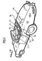
- FIG. 2 An embodiment of a wind deflector according to the invention, which in Figure 2 shown and there designated as a whole with 10, is on one in Figures 1 and 2 as a whole with 12 designated roll bar
- Motor vehicle body 14 of a passenger vehicle can be determined.
- Passenger motor vehicle is preferably a convertible vehicle.
- the roll bar 12 stands over a belt line or parapet line 16 the vehicle body 14 upward and includes two at a distance Arch elements 18 and 20 arranged in relation to one another. These are next to one another each behind backrests 22 and 24 arranged in a passenger compartment 26 Sitting the convertible vehicle arranged.
- the arch elements 18 and 20 are in one variant of an embodiment basically the same design, for example in the form of a U-bend, whose leg opening points down towards the convertible vehicle. They extend in a plane transverse to a longitudinal direction 28 of the motor vehicle body 14.
- An arch element 18, 20 comprises a first arch section 30 in the shape of a middle leg, on the left and right in each case a second arch section 32 and a third arch section 34 in the Shape of side legs connects.
- the side legs 32 and 34 in turn are connected to a base support 36 of the roll bar 12.
- the basic carrier 36 runs between the arch elements 18 and 20 (this is shown in FIG Figure 2 not shown). In the variant shown in Figures 1 and 2 runs the base support 36 also between the side legs 32 and 34, that is, the U-shaped arch elements 18, 20 are in the shown Variant taking into account the basic support D-shaped.
- the arch elements 18, 20 are provided with a cladding 38.
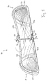
- a first exemplary embodiment of a wind deflector 10, which is shown in FIG Whole is denoted by 40, a carrier device 42, which on the roll bar 12 can be fixed, and which wind blocker surface elements 44 holds.
- the carrier device 42 comprises a frame structure 46 with upper ones Frame parts 48a, 48b and lower frame parts 50a, 50b.
- At the Roll bar 12 mounted support device 42 are the lower frame parts 50a, 50b facing the base support 36 of the roll bar 12.
- a side bracket 52a, 52b is arranged between the associated upper frame part 48a and lower frame part 50a or 48b, 50b.
- the upper frame parts 48a and 48b are connected via a swivel joint 54 Pivot axis transverse to the upper frame parts 48a, 48b relative to one another pivotable.
- the swivel joint 54 is preferably essentially arranged centrally on the frame structure 46.
- a Swivel joint 56 is provided, by means of which the lower frame parts 50a and 50b are pivotable relative to one another, the pivot joints 54 and 56 are arranged and aligned with respect to each other so that they are a common one Have pivot axis.
- a length of the carrier device can be 42 related to the plane in which the arch elements 18, 20 of the roll bar 12 lie, change. This change in length is accompanied by a change the depth dimension of the carrier device 42 transversely to said one Level: If the depth extension is minimal, then the length of the carrier device 42 in the above-mentioned level and vice versa.
- the locking element 58 is designed as a swivel flap, which is arranged on the upper frame part 48b and pivotable with a Pivot axis transverse to the upper frame part 48b and transverse to the pivot axis of the swivel joint 54 is mounted.
- the flap is channel-shaped with the channel opening facing downwards and this is adapted to an outer surface of the upper frame part 48a in the region of the swivel joint 54
- the flap 58 projects parallel to the upper frame part 48b upper frame part 48b and can if the upper frame parts 48a and 48b aligned at least in the area of the swivel joint 54 are on the surface of the upper frame part 48a. This is the The upper frame parts 48a, 48b can be pivoted back relative to one another and by means of the latching element 58 is therefore a fixing position 60 ( Figure 3) of the carrier device 42 lockable.
- This setting position 60 corresponds essentially to a position in which the carrier 42 a maximum length with respect to the plane in which the arch elements 18 and 20 have.
- the fixing position 60 defined by a dead center of the pivotability of the upper frame parts 48a and 48b relative to each other, in which an end face 62a of the upper frame part 48a to an end face 62b of the upper Frame part 48b abuts and thus a further pivotability of the upper Frame parts 48a and 48b are locked relative to each other.
- the lower frame part 50b is also provided with a locking element 64, which is basically designed and arranged the same as with reference the upper frame parts 48a and 48b for the locking element 58 described.
- the locking element 64 on the lower Frame part 50a is arranged.
- Holding tab 66a, 66b arranged, which are each formed channel-shaped with a gutter opening that faces outwards.
- the retaining tabs 66a, 66b are respectively to the second arc sections 32 of the arc elements 18 and 20 adapted in shape so that a retaining tab 66a or 66b an inside of the second arch section 32 of the associated arch element 18 or 20 can be applied and partially the associated arch element 18, 20 can engage around the second arc section 32.
- the retaining tabs 66a, 66b made of an elastic material manufactured so that they have a spring action, in particular the carrier device 42 via the retaining tabs 66a, 66b on the roll bar 12 can be clamped.
- FIG. 2 In the embodiment shown in Figure 2 is left and right, respectively from the pivot joint 54 at a distance from this and preferably symmetrical to the pivot axis between the upper frame part 48a and the lower frame part 50a a support strut 68a and between the upper frame part 48b and the lower frame part 50b a support strut 68b arranged.
- the support struts 68a and 68b connect the upper frame parts 48a, 48b with the lower frame parts 50a, 50b and thereby increase the Cross stability of the carrier device.
- the wind blocker surface elements 44 are in particular by a wind deflector track 70 formed, which is preferably made of a flexible material web is made, which in turn from an air-permeable, but for Windproof net or fabric is formed.
- This wind deflector track 70 is arranged and formed on the carrier device 42 so that they have the pivotability of the frame parts 48a, 48b and 50a, 50b relative not hindered each other and on the other hand with the mounted carrier device 42 is essentially tensioned in the fixing position 60.
- a first wind deflector track 72a is stretched and between the upper frame part 48b and the lower frame part 50b, a second wind deflector track 72b is tensioned, wherein the two wind deflector webs 72a and 72b have mesh directions, which in the area of the pivot axis of the pivot joints 54, 56 in one Angles meet.
- the wind deflector tracks 72a and 72b are in the area 74 in which they meet, woven together.
- the material of the wind deflector web 72a and 72b elastic so as not to hinder the relative pivotability of the frame structure 46.
- the wind deflector according to the invention works as follows:
- the wind deflector 40 can be stored in a space-saving manner in which the frame structure 46 is pivoted so that the upper frame parts 48a and 48b are facing each other and aligned substantially parallel to each other are.
- the length of the carrier device 42 is then essentially that Reduces half of its maximum length and the depth of the carrier 42 to essentially double their minimum depth.
- the Frame structure 46 unfolded and in particular expanded so far that the Retaining tabs 66a and 66b are located on the inside of the second arc sections 32 let the respective arch elements 18 and 20 create.
- the frame parts 48a, 48b and 50a, 50b then become further relative to one another with the application of force pivoted until the fixing position 60 is reached.
- the retaining tabs 66a and 66b are formed from an elastic material, they practice in the fixing position 60 a force on the assigned second arc sections 32 of the respective arch elements 18 and 20, this force is directed outwards.
- the carrier device 42 and thus the wind blocker As a result, as shown in FIG. 3, 40 is held in a clamped manner on the roll bar 12.
- wind deflector 40 By clamping the wind deflector 40 on the roll bar 12 must the latter cannot be or will not be prepared for holding a wind deflector.
- the wind deflector 40 can also be easily attached to the roll bar 12 assemble and remove itself in a simple way by the above mentioned steps are carried out in the opposite direction. Also lets store the wind deflector 40 to save space.
- the wind deflector 40 is on the roll bar 12 on its side facing away from the passenger compartment 26. Thereby the wind deflector 40 is not in the passenger compartment 26, which creates the risk of injury is reduced in the event of accidents.
- the wind deflector according to the invention can, however, on each side the roll bar 12.
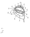
- FIG whole A variant of the wind blocker 40 according to FIG. 2 and FIG. 3 is shown in FIG whole designated 76.
- This wind blocker 76 is basically of the same design, like the wind deflector 40 and works like this. Same Elements are therefore designated with the same reference symbols.
- the wind blocker 76 differs from the wind blocker 44 in that a support strut 78a which between the upper frame part 48a and is arranged lower frame part 50a, is arcuate and in its shape is adapted to the third arch section 34 of the arch element 20. Furthermore, the support strut 78a is arranged so that when assembled Carrier device 42 lies in the region of the arch element 20. The arch element 20 then covers the support strut 78a.
- the support strut 78b is similar arranged between the upper frame part 48b and the lower frame part 50b and trained.
- a support strut 82 through a pivot shaft between the pivot joint 54 and the swivel joint 56, that is to say the swivel joint 54 on the upper frame parts 48a, 48b and the swivel joint 56 on the lower frame parts 50a and 50b are supported on one another. Otherwise the wind deflector 80 functions as described above.
- a slider 84 can also be provided, which in a groove 86a of the upper frame part 48a and in a groove 86b of the upper Frame part 48b is guided.
- a slide 84 is particularly in the Frame structure 46 can be integrated in such a way that it is not noticeable and so the aesthetic Overall impression is not disturbed by locking elements.
- the grooves 86a and 86b are arranged so that they are in the fixing position 60th are aligned with each other so that the slide from an upper Frame part, for example the upper frame part 48b, into the other frame part, for example, be moved from the upper frame part 48a can, the slide then lying partly in the groove 86a and partly in the groove 86b and thus a further pivoting of the upper frame parts 48a and 48b is locked, that is, the fixing position 60 is locked.
- the slide 84 is in particular captively guided in the groove 86b and such that it can be fully immersed in the pivoting movements not to hinder before reaching the definition position 60.
- the lower frame parts 50a and 50b can also be made in the same way lock together.
- Fixing position beyond a dead center of the pivoting movement of the Frame structure 46 lies.
- a wind deflector according to the invention which is designated as a whole in FIG. 7 with 88 comprises one as a whole with 90 designated a first support structure 92, which can be fixed to the arch element 20, and a second support structure 94, which can be fixed on the arch element 18.
- the first support structure 92 and the second carrier structure 94 are fundamentally the same, but mirror-symmetrical trained to each other. The following is therefore only the first Support structure 92 described in more detail.
- the first support structure 92 is corresponding to the Adjusted arc sections 30, 32 and 34 of the arc element 20, namely on the inside ( Figure 9).
- the first carrier structure 92 has one Frame 100 with a middle leg 102, side legs 104 and 106 and a connecting leg 108 between the side legs 104 and 106 on.
- the wind deflector track 96 is located on these legs 102, 104, 106 and 108 held.
- the first support structure 92 with its legs is designed that the opening 98 is substantially completely covered.
- a holding tab 110 is arranged, which is basically the same as the above in connection with the Holding tab 66a described in the first embodiment.
- the holding tab 110 serves to apply the first support structure 92 to an inside of the second Arc section 32, which arc section 32 an outside of the Convertible vehicle is facing.
- a holding tab 112 On the side leg 104 of the first support structure 92 is a holding tab 112 arranged, which has a trough-shaped element 114, which for Serves on an inside of the third arc section 34, this third arc section 34 facing the interior of the convertible vehicle is.
- the holding tab 112 is in particular at least in the region of the channel-shaped Elements 114 made of an elastic material so that the first support structure can be attached to the arch element 20 by means of the holding tab 110 is and the groove-shaped element for applying the retaining tab 112 114 can be deformed elastically such that the blocking by the third Arch section 34 can be overcome and then the first support structure 92 is held clamped on the arch element 20.
- tolerance compensation can also be made, for example, in relation to manufacturing tolerances achieve.
- the retaining tab 112 has one that is connected to it in one piece Groove element 116, which when the first support structure is inserted 92 is arranged facing the other arch element 18 and thereby offset to the level of the arch elements 18, 20.
- a groove 118 of the groove element 116 runs transversely to a distance direction between the Arch elements 18 and 20.
- a carrier 120 can be inserted into this groove 118, which wind blocker surface element 122 carries or a wind blocker surface element itself represents.
- a corresponding groove 124 of the second carrier structure 94 is in this case when this second support structure 94 is inserted into the arch element 18, the groove 118 facing.
- the carrier 120 can then be in the space between insert the arch elements 18 and 20 into the grooves 118 and 124.
- the structure is 120 and the grooves 118 and 124 are so formed such that a downward displacement of the carrier 120 is limited; the carrier 120 is movable downwards, the base carrier 36 the roll bar 12 to, fixable, in particular by a stop, which by the interaction between the carrier 120 when it is inserted into the grooves 118 and 124, is formed with these grooves.
- the grooves 118 and 124 are formed in an arc shape based on the first support structure 92 and the second support structure 94 arranged mirror-symmetrically to each other.
- the carrier 120 is at its end End faces 126, 128 are also arcuate in shape such that a lower face 130 is shorter than an upper face 132. This allows the carrier 120 in the on the arch elements 18th or 20 fixed grooves 124 or 118 and move downwards, however, from a certain position the movability is limited.
- the grooves 118, 124 are, for example provided with recesses 134 (FIG. 9), into the latching lugs, of the carrier 120 can snap into place.
- Other locking means can also be provided such as positive locking means for fixing the carrier 120 to the carrier structures 92, 94.
- the carrier 120 can in particular by a disc such as be formed of a plexiglass pane. But it can also be a frame structure be provided with a wind deflector fixed to it.
- a support structure 92, 94 can in particular be in the form of a one-piece plastic injection molded part be formed, the associated wind blocker surface element is formed in one piece on this injection molded part (it is then no mesh or fabric provided as a wind blocker surface element).
- the wind blocker is therefore 88 in three parts: the first support structure 92 is provided for the arch element 20, the second support structure 94 for the arch element 18 and the support 120, which is held by the two support structures 92 and 94, for the Gap between the arch elements 18 and 20.
- a carrier device is provided with tabs which the arch elements 18, 20 on their respective at least partially embrace the opposite outer sides.
- the support structure for a wind blocker surface element between the arch elements 18 and 20 is then separate from the support structures for the respective wind blocker surface elements for the arch elements 18, 20.
- the wind deflector 88 according to the invention can be attached to the roll bar as follows Set 12:
- the holding tab of a carrier structure for example the holding tab 110 of the second support structure 94, is on the inside of the second arc section 32 of the arch element 18 and the second support structure 94 is then turned towards the third arc section 34 (FIG. 8).
- the retaining tab on the third arc section 34 can be fixed by being elastically deformed and then, after overcoming the lock, the elastic deformation is released and afterwards the second support structure 94 is held clamped on the arch element 18.
- a support structure is not held clamped to an arch element, but only abuts and the final fixation takes place only via the structure 120.
- the first Carrier structure 92 proceeded. Thereafter, the grooves 118 are the first support structure 92 and 124 of the second support structure 94 are aligned with one another in a plane parallel to the plane of the arch elements 18 and 20.
- the carrier 120 can then be used for the wind blocker surface elements be used.
- the carrier 120 prevents rotating the support structures 92 and 94 away from the support structure 120, so that after insertion in grooves 118 and 124 the final fixation of the carrier device 90 on the roll bar 12.
Abstract
Description
Die Erfindung betrifft ein Windschott für ein Personenkraftfahrzeug mit Überrollbügel, umfassend Windschott-Flächenelemente und eine Trägervorrichtung für die Windschott-Flächenelemente, welche an dem Überrollbügel festlegbar ist.The invention relates to a wind deflector for a passenger vehicle with a roll bar, comprising wind blocker surface elements and a carrier device for the wind deflector surface elements, which can be attached to the roll bar is.
Ein derartiges Windschott ist beispielsweise aus der DE 195 34 584 C1 oder der DE 196 32 352 A1 bekannt.Such a wind deflector is for example from DE 195 34 584 C1 or known from DE 196 32 352 A1.
Ein Windschott, welches an einem Überrollbügel festgelegt ist, dient dazu, Insassen des Personenkraftfahrzeuges, welche vor dem Überrollbügel sitzen, vor rückwärts einströmender Luft zu schützen.A wind deflector, which is attached to a roll bar, serves for occupants of the passenger car sitting in front of the roll bar to protect air flowing backwards.
Davon ausgehend liegt der Erfindung die Aufgabe zugrunde, ein Windschott zu schaffen, welches auf einfache Weise an einem Überrollbügel festlegbar ist.Based on this, the invention is based on the object of closing a wind deflector create, which can be easily fixed on a roll bar.
Diese Erfindung wird bei einem Windschott der eingangs genannten Art erfindungsgemäß dadurch gelöst, daß die Trägervorrichtung mindestens zwei in einem Abstand angeordnete Haltelaschen aufweist und daß die Haltelaschen so angeordnet und ausgebildet sind, daß sie an jeweiligen Bügelabschnitten des Überrollbügels zur Festlegung der Trägervorrichtung an dem Überrollbügel anlegbar sind.This invention is invented in a wind deflector of the type mentioned at the outset solved in that the carrier device at least two in has a spaced holding tabs and that the holding tabs so are arranged and designed so that they on respective bracket sections of the Roll bar to fix the support device to the roll bar can be created.
Dadurch, daß die Trägervorrichtung Haltelaschen aufweist, kann die Trägervorrichtung an einem Überrollbügel festgelegt werden, der nicht vorgerüstet zu sein braucht. Insbesondere braucht der Überrollbügel nicht mit Ausnehmungen zur Aufnahme der Trägervorrichtung versehen sein. Dadurch ist bei dem erfindungsgemäßen Windschott der Überrollbügel zum einen weniger anfällig gegenüber beispielsweise Schmutzablagerungen und dergleichen und andererseits wird der ästhetische Gesamteindruck durch Ausnehmungen oder dergleichen nicht gestört. Auch lassen sich vorgegebene Überrollbügel mit einem erfindungsgemäßen Windschott nachrüsten.Because the carrier device has retaining tabs, the carrier device can be fixed to a roll bar that is not pre-equipped needs to be. In particular, the roll bar does not need recesses be provided for receiving the carrier device. This is in the inventive Wind deflector of the roll bar on the one hand less susceptible to for example, dirt deposits and the like and on the other hand is the overall aesthetic impression through recesses or the like not bothered. It is also possible to use predetermined roll bars with an inventive one Retrofit wind deflector.
Das erfindungsgemäße Windschott läßt sich über die Haltelaschen auf einfache und schnelle Weise an einem Überrollbügel montieren und ebenso wieder leicht entfernen.The wind deflector according to the invention can be easily attached to the retaining tabs and quickly assemble on a roll bar and again remove easily.
Dadurch, daß die Trägervorrichtung mindestens zwei in einem Abstand angeordnete Haltelaschen aufweist, ist es möglich, die Trägervorrichtung über Klemmkraftwirkung an dem Überrollbügel zu halten, das heißt es müssen keine Formschlußelemente zur Verbindung mit dem Überrollbügel vorgesehen werden. Die Haltelaschen sind dabei insbesondere starr ausgebildet, wobei sie aber eine bestimmte Elastizität aufweisen können, um eben eine klemmende Fixierung (beispielsweise in der Art eines Schnappverschlusses) zu ermöglichen.Characterized in that the carrier device arranged at least two at a distance Has retaining tabs, it is possible to over the carrier device To hold the clamping force on the roll bar, that means it must no positive locking elements are provided for connection to the roll bar become. The retaining tabs are in particular rigid, and they but can have a certain elasticity, just a jamming To allow fixation (for example in the manner of a snap lock).
Besonders vorteilhaft ist es, wenn eine Haltelasche so ausgebildet ist, daß ein korrespondierender Bügelabschnitt durch sie mindestens teilweise umgreifbar ist. Dadurch läßt sich ein guter Halt der Trägervorrichtung an einem Überrollbügel erreichen und zwar insbesondere über Klemmkraftwirkung. Da die Haltelasche gewissermaßen um einen korrespondierenden Bügelabschnitt legbar ist, ist dadurch auch die Montage der Trägervorrichtung erleichtert, denn durch eine mindestens teilweise umlegbare Haltelasche an einem Bügelabschnitt ist eine "Referenzposition" bei der Montage geschaffen. Eine Lasche kann dabei so ausgebildet sein, daß sie einen Überrollbügel so weit umgreifen kann, daß sie auch über einen Scheitelpunkt einer abgerundeten Oberfläche des Überrollbügels hinaus am Überrollbügel anlegbar ist. Die Lasche ist dazu vorzugsweise elastisch ausgebildet, um eine entsprechende Aufschiebbarkeit auf den Überrollbügel zu ermöglichen. Bei aufgeschobener Lasche stellt der den Scheitel bildende Bereich des Überrollbügels eine Sperre gegen die Loslösung der Lasche vom Überrollbügel weg dar.It is particularly advantageous if a retaining tab is designed so that a corresponding bracket section can be at least partially encompassed by them is. This allows a good hold of the carrier device on a roll bar achieve and in particular via clamping force. Because the retaining tab to a certain extent can be placed around a corresponding bracket section is, this also facilitates the assembly of the carrier device, because by is an at least partially foldable retaining tab on a bracket section created a "reference position" during assembly. A tab can do this be trained so that they can grip a roll bar so far that they also over an apex of a rounded surface of the roll bar can also be placed on the roll bar. The tab is preferred designed to be elastic so that it can be pushed onto the roll bar to enable. When the tab is slid on, it forms the apex forming area of the roll bar a lock against the detachment of the Flap away from the roll bar.
Ganz besonders günstig ist es, wenn eine Haltelasche an die Abmessungen des Bügelabschnittes, an welchen sie angelegt werden soll, in ihrer Form angepaßt ist. Dadurch ist für einen sicheren Halt der Trägervorrichtung an dem Überrollbügel gesorgt, wobei ein befriedigender ästhetischer Gesamteindruck erzielbar ist.It is particularly favorable if a retaining tab is attached to the dimensions of the Adjusted the shape of the bracket portion to which it is to be applied is. This ensures a secure hold of the carrier device on the roll bar taken care of, whereby a satisfactory overall aesthetic impression can be achieved is.
Bei einer fertigungstechnisch günstigen Ausführungsform ist eine Haltelasche rinnenförmig ausgebildet. Da ein Überrollbügel in der Regel Bügelelemente aufweist, welche rohrförmig ausgestaltet sind mit einer darauf angeordneten Verkleidung, läßt sich auf diese Weise ein mindestens teilweises Umgreifen des Bügelabschnitts durch eine Haltelasche auf einfache Weise erreichen.In one embodiment that is favorable in terms of production technology, there is a retaining tab channel-shaped. Since a roll bar usually has bracket elements has, which are tubular with an arranged thereon Cladding, an at least partial embracing of the Reach the bracket section through a retaining tab in a simple manner.
Ganz besonders vorteilhaft ist es, wenn eine Haltelasche elastisch ausgebildet ist und insbesondere federnd ausgebildet ist. Dadurch ist erreichbar, daß in einer Festlegungsstellung eine Klemmkraft ausübbar ist, welche die Trägervorrichtung an dem Überrollbügel festlegt. Durch die elastische Ausbildung läßt sich die Festlegungsstellung auf einfache Weise unter Kraftaufwand zur elastischen Verformung erreichen, insbesondere ohne daß besondere Werkzeuge vorgesehen werden müssen. It is particularly advantageous if a retaining tab is designed to be elastic is and in particular is resilient. It is thereby achievable that in a fixing position a clamping force can be exerted, which the carrier device attached to the roll bar. Due to the elastic training the fixing position in a simple manner with effort to elastic Achieve deformation, especially without special tools must be provided.
Ganz besonders vorteilhaft ist es, wenn eine Haltelasche über eine Windschott-Flächenelement-Ebene der Trägervorrichtung hinausragt. Dadurch läßt sich das erfindungsgemäße Windschott über die Haltelaschen in Bügelelemente des Überrollbügels einsetzen, wobei dann die Windschott-Flächenelement-Ebene versetzt zu einer Ebene des Überrollbügels liegt. Insbesondere ist es dadurch nicht notwendig, die Trägervorrichtung an die spezielle Ausgestaltung des Überrollbügels anzupassen, das heißt beispielsweise an den Zwischenraum zwischen zwei Bügelelementen anzupassen, sondern die Anpassung muß nur gegenüber der Trägervorrichtung des Windschottes erfolgen.It is particularly advantageous if a retaining tab over a wind blocker surface element level protrudes from the carrier device. This allows the wind deflector according to the invention on the retaining tabs in bracket elements of Insert roll bar, then the wind deflector surface element level is offset to a level of the roll bar. In particular, it is not necessary, the carrier device to the special design of the Adjust roll bar, that is, for example, to the space to adjust between two bracket elements, but the adjustment only needs to against the support device of the wind blocker.
Günstig ist es, wenn die mindestens zwei Haltelaschen an oder in der Nähe gegenüberliegender seitlichen Ende der Trägervorrichtung angeordnet sind. Dadurch lassen sich die zwei äußeren Haltelaschen an äußere Bügelabschnitte anlegen, wobei diese äußeren Bügelabschnitte insbesondere gegenüber liegen. Dadurch wiederum läßt sich eine gute Klemmkraftwirkung zur Festlegung der Trägervorrichtung an dem Überrollbügel erreichen.It is beneficial if the at least two retaining tabs are on or nearby opposite side end of the carrier device are arranged. This allows the two outer retaining tabs to be attached to outer bracket sections create, these outer bracket sections are particularly opposite. This in turn allows a good clamping force effect to be used to determine the Reach the carrier device on the roll bar.
Weist der Überrollbügel eine oder mehrere Bogenelemente auf, dann ist es besonders günstig, wenn eine Haltelasche so angeordnet und ausgebildet ist, daß sie an einer Innenbogenseite eines jeweiligen Bügelabschnitts des Bogenelementes anlegbar ist. Dadurch läßt sich eine Trägervorrichtung an den Bogenelementen in einer Festlegungsstellung verspannen. Insbesondere ist es dann sehr vorteilhaft, wenn die mindestens zwei Haltelaschen so an der Trägervorrichtung in einem Abstand angeordnet sind, daß ihre Flächenrichtungen bezüglich einer Anlagefläche an dem Überrollbügel jeweils entgegengesetzt nach außen weisen. Die Haltekräfte und insbesondere Klemmkräfte der Trägervorrichtung in der Festlegungsstellung der Trägervorrichtung weisen dann nach außen (von dem Fahrzeuginneren weg) und zwar an den jeweiligen Außenabschnitten der beiden Bügelelemente entgegengesetzt, so daß auf diese Weise eine hohe Klemmkraftwirkung erreichbar ist.If the roll bar has one or more arch elements, then it is Particularly favorable if a retaining tab is arranged and designed that they are on an inner arc side of a respective bracket portion of the arch element can be created. This allows a carrier device on the arch elements clamp in a fixing position. In particular it is then very advantageous if the at least two retaining tabs on the carrier device are arranged at a distance that their surface directions opposite each other with respect to a contact surface on the roll bar point outwards. The holding forces and in particular clamping forces of the carrier device then point in the fixing position of the carrier device to the outside (away from the vehicle interior) at the respective one Outer sections of the two bracket elements opposite, so that on this way a high clamping force effect can be achieved.
Bei einem Ausführungsbeispiel ist die Trägervorrichtung einteilig ausgebildet. Diese läßt sich auf einfache Weise lagern und auch montieren.In one embodiment, the carrier device is formed in one piece. This can be easily stored and assembled.
Günstig ist es dabei, wenn die Trägervorrichtung eine Rahmenstruktur aufweist, um so einerseits eine Gewichtsersparnis zu erzielen und andererseits um auf einfache Weise Windschott-Flächenelemente wie luftdurchlässige aber windundurchlässige Windabweiserbahnen aus einem Netz oder Gewebe zu halten.It is advantageous if the carrier device has a frame structure, in order to save weight on the one hand and on the other hand to wind deflector surface elements such as air-permeable in a simple manner windproof wind deflectors made from a net or fabric hold.
Ganz besonders vorteilhaft ist es, wenn die Trägervorrichtung so ausgebildet ist, daß ihre Länge parallel zum Überrollbügel veränderbar ist. Es läßt sich dadurch eine platzsparende Lagerung des Windschotts erreichen, wenn die entsprechende Länge minimiert wird. Andererseits läßt sich solch eine Trägervorrichtung auf einfache Weise an einen Überrollbügel montieren, indem die Haltelaschen angesetzt werden, die Länge dann durch Kraftbeaufschlagung vergrößert wird, bis die Festlegungsstellung erreicht wird, und in dieser Festlegungsstellung insbesondere die Haltelaschen an entsprechenden Bügelabschnitten des Überrollbügels anlegen und auf diese eine Kraft ausüben und zwar an den jeweiligen Enden des Überrollbügels nach außen wirkend. Die Trägervorrichtung ist dann durch Klemmkraft an dem Überrollbügel festgehalten.It is very particularly advantageous if the carrier device is designed in this way is that its length can be changed parallel to the roll bar. It can be done achieve space-saving storage of the wind deflector if the appropriate Length is minimized. On the other hand, such a carrier device can be Easily mount to a roll bar by holding the tabs be applied, the length is then increased by applying force until the determination position is reached and in this determination position in particular the retaining tabs on corresponding bracket sections of the roll bar and exert a force on it and acting outwards at the respective ends of the roll bar. The Carrier device is then held on the roll bar by clamping force.
Konstruktiv besonders günstig ist es, wenn die Trägerstruktur zur Längenänderung ein oder mehrere Schwenkgelenke aufweist. Durch ein solches Schwenkgelenk lassen sich Teile der Trägerstruktur relativ zueinander verschwenken und die Trägerstruktur weist dadurch Stellungen auf, in denen ihre Länge minimiert ist (Aufbewahrungsstellung oder Lagerstellung) und eine Stellung, in welcher die Länge maximiert ist und in welcher die Trägervorrichtung an einem Überrollbügel durch Klemmkraft fixierbar ist (Festlegungsstellung). Die Montage einer solche Trägerstruktur an einem Überrollbügel läßt sich einfach und schnell bewirken. Weiterhin lassen sich Schwenkgelenke auf kostengünstige Weise derart robust ausbilden, daß ihre Funktionsfähigkeit auch auf einen längeren Zeitraum hinaus nicht beeinträchtigt wird.It is structurally particularly favorable if the support structure for changing the length has one or more swivel joints. Through one Parts of the support structure can be pivoted relative to one another and the support structure thereby has positions in which its Length is minimized (storage position or storage position) and one Position in which the length is maximized and in which the carrier device can be fixed to a roll bar by clamping force (fixing position). The assembly of such a support structure on a roll bar can effect quickly and easily. Furthermore, swivel joints can be opened Inexpensive way train so robust that their functionality is not impaired for a longer period of time.
Vorteilhafterweise ist ein Schwenkgelenk zumindest näherungsweise mittig an einer Rahmenstruktur der Trägervorrichtung angeordnet. Dadurch läßt sich einerseits in der Aufbewahrungsstellung eine minimale Länge der Trägervorrichtung herstellen und andererseits ist die Montage erleichtert, da die Festlegungsstellung durch symmetrische Kraftbeaufschlagung erreichbar ist.A pivot joint is advantageously at least approximately in the center arranged a frame structure of the carrier device. This allows on the one hand, in the storage position, a minimal length of the carrier device produce and on the other hand, the assembly is easier because the fixing position can be reached by symmetrical application of force.
Ganz besonders vorteilhaft ist es, wenn in einer Festlegungsstellung der Trägervorrichtung diese mittels der mindestens zwei Haltelaschen an dem Überrollbügel klemmend festlegbar ist.It is very particularly advantageous if in a fixing position of the carrier device this by means of the at least two retaining tabs on the roll bar can be fixed by clamping.
Bei einer Variante einer Ausführungsform ist es vorgesehen, daß die Festlegungsstellung jenseits eines Totpunktes bezüglich einer Schwenkposition relativ zu einer schwenkbaren Teile der Trägervorrichtung liegt.In a variant of an embodiment it is provided that the fixing position beyond a dead center with respect to a pivot position is relative to a pivotable part of the carrier device.
Günstig ist es, wenn die Festlegungsstellung verriegelbar ist. Dadurch ist die Festlegung der Trägervorrichtung an dem Überrollbügel fixierbar. It is favorable if the fixing position can be locked. This is the Fixing the carrier device on the roll bar fixable.
Bei einer Variante einer Ausführungsform ist zur Verriegelung der Festlegungsposition mindestens ein Rastelement vorgesehen, durch welches relativ zueinander bewegliche Teile einer Rahmenstruktur der Trägervorrichtung untereinander im wesentlichen unbeweglich koppelbar sind. Das Rastelement sperrt dadurch die Schwenkbewegung und damit ein Rückschwenken aus der Festlegungsstellung.In a variant of an embodiment, the locking position is for locking at least one locking element is provided, by which relative mutually movable parts of a frame structure of the carrier device are essentially immovably coupled to one another. The locking element blocks the swiveling movement and thus swiveling back out of the Securing position.
Bei einer konstruktiv einfachen Ausführungsform ist das Rastelement als Schwenkklappe ausgebildet. Eine solche Schwenkklappe wird in der Festlegungsstellung über benachbarte, relativ zueinander schwenkbare Rammteile gelegt und koppelt diese miteinander im wesentlichen unbeweglich, um so ihre relative Schwenkbewegung zueinander zu sperren.In a structurally simple embodiment, the locking element is as Swing flap formed. Such a swivel flap is in the fixing position via adjacent ram parts that can be pivoted relative to each other placed and couples them essentially immovably, so as to theirs to lock relative pivoting movement to each other.
Bei einer alternativen Variante ist das Rastelement als Rastschieber ausgebildet, welcher ebenfalls die Schwenkbewegung sperrt, wenn er in einer Raststellung ist.In an alternative variant, the locking element is designed as a locking slide, which also blocks the pivoting movement when it is in a locked position is.
Günstig ist es, wenn eine oder mehrere Streben zwischen einem oberen Rahmenteil und einem unteren Rahmenteil der Rahmenstruktur angeordnet sind. Diese Streben sorgen für eine Querstabilität des Windschottes quer zu einer Flächennormalen-Richtung der Windschott-Flächenelemente.It is favorable if one or more struts between an upper frame part and a lower frame part of the frame structure are arranged. These struts ensure transverse stability of the wind blocker across one Surface normal direction of the wind blocker surface elements.
Bei einer Variante einer Ausführungsform ist eine Stützstrebe als Schwenkwelle eines Schwenkgelenks zur Längenänderung der Trägervorrichtung ausgebildet. Eine solche Stützstrebe hat auch den Vorteil, daß sie Schwenkgelenke in einem oberen Rahmenteil und einem unteren Rahmenteil koppeln kann, wodurch eine gute Schwenkführung erreichbar ist. In a variant of an embodiment, a support strut is used as a pivot shaft a swivel joint designed to change the length of the carrier device. Such a support strut also has the advantage that it has swivel joints couple in an upper frame part and a lower frame part can, whereby a good swivel guide can be achieved.
Bei einer weiteren Variante einer Ausführungsform, welche alternativ oder kumulativ sein kann, sind Stützstreben so angeordnet und ausgebildet, daß sie beim montierten Windschott im Bereich von Bügelabschnitten des Windschottes liegen. Solche Stützstreben sind dann bei montiertem Windschott relativ unauffällig und stören damit auch nicht den ästhetischen Gesamteindruck und insbesondere wird dadurch das Blickfeld des Fahrers nach hinten im Innenspiegel nicht behindert. Betrachtet man den Überrollbügel von einer der Montageseite des Windschotts abgewandten Seite, dann sind diese Stützstreben überhaupt nicht sichtbar.In a further variant of an embodiment, which alternatively or can be cumulative, support struts are arranged and designed so that they When the wind deflector is installed in the area of the bow sections of the wind deflector lie. Such support struts are then relative when the wind deflector is installed inconspicuous and therefore do not disturb the overall aesthetic impression and in particular, this increases the driver's field of vision to the rear in the interior mirror not disabled. If you look at the roll bar from one of the assembly sides side facing away from the wind deflector, then these are support struts not visible at all.
Bei einem weiteren Ausführungsbeispiel umfaßt der Überrollbügel mindestens ein erstes und eine zweites beabstandetes Bogenelement und die Trägervorrichtung einer ersten Trägerstruktur, welche an dem ersten Bogenelement festlegbar ist, und eine zweite Trägerstruktur, welche an einem zweiten Bogenelement festlegbar ist. Es ist damit eine eigene Trägerstruktur für jedes Bogenelement vorgesehen, wobei sich in dem Zwischenraum zwischen den Bogenelementen entsprechende Windschott-Flächenelemente an der ersten Trägerstruktur und der zweiten Trägerstruktur selber montieren lassen.In a further embodiment, the roll bar comprises at least a first and a second spaced arc element and the carrier device a first support structure, which on the first arch element is fixable, and a second support structure, which on a second arch element is definable. It is a separate support structure for everyone Arch element provided, wherein in the space between the Wind deflector surface elements corresponding to arch elements on the first Have the support structure and the second support structure assembled by yourself.
Vorteilhafterweise ist durch eine Trägerstruktur ein Windschott-Flächenelement für das zugeordnete Bogenelement gehalten. Das Bogenelement selber weist eine Öffnung auf, in welche eine zugeordnete Trägerstruktur einsetzbar ist. Durch diese Öffnung des Bogenelementes selber können störende Luftströmungen aus diesem Bereich des Fahrzeugs zu Fahrzeuginsassen strömen. Das Windschott-Flächenelement, welches durch die entsprechende Trägerstruktur gehalten ist, verhindert derartige störende Luftströmungen zu Fahrzeuginsassen hin. A wind blocker surface element is advantageously provided by a support structure held for the associated arch element. The arch element itself has an opening into which an assigned support structure can be inserted is. This opening of the arch element itself can cause disruptive air currents flow from this area of the vehicle to vehicle occupants. The wind blocker surface element, which by the corresponding support structure is held, prevents such disturbing air flows to vehicle occupants out.
Vorteilhafterweise ist zwischen der ersten Trägerstruktur und der zweiten Trägerstruktur ein Träger für Windschott-Flächenelemente für den Zwischenraum zwischen den Bogenelementen festlegbar. Dadurch wird die optimale Funktion des Windschotts gewährleistet. Die Trägerstrukturen dienen dann als Haltevorrichtungen für den Träger.It is advantageous between the first support structure and the second support structure a support for wind deflector surface elements for the space definable between the arch elements. This will ensure the optimal function of the wind deflector guaranteed. The support structures then serve as holding devices for the wearer.
Bei einer Variante einer Ausführungsform ist der Träger für den Zwischenraum zwischen den Bogenelementen scheibenförmig ausgebildet, beispielsweise als Plexiglasscheibe. Dies hat den Vorteil, daß zum einen ein guter Windschutz erreichbar ist und zum anderen die Sicht des Fahrers nach hinten nicht behindert ist.In a variant of an embodiment, the carrier is for the intermediate space disc-shaped between the arch elements, for example as Plexiglass window. This has the advantage that, on the one hand, good wind protection is reachable and secondly does not obstruct the driver's view to the rear is.
Zur Fixierung einer Trägerstruktur an einem Bogenelement ist es besonders günstig, wenn eine Trägerstruktur gegenüberliegende Haltelaschen zu deren Festlegung an einem zugeordnetem Bogenelement aufweist und auch zur Festlegung eines Trägers zwischen beabstandeten Trägerstrukturen. Mittels solcher Haltelaschen läßt sich dann die Trägerstruktur an dem jeweiligen Bogenelement halten, beispielsweise über Klemmwirkung. Die Trägerstruktur kann dabei in einer Mittelebene von Bogenelementen oder versetzt dazu gehalten sein.It is special for fixing a support structure to an arch element favorable if a support structure opposite holding tabs to their Has fixing on an associated arch element and also for Definition of a support between spaced support structures. through Such holding tabs can then be the support structure on the respective arch element hold, for example via clamping action. The support structure can be held in a central plane of arch elements or offset to it his.
Insbesondere vorteilhaft ist es, wenn eine Haltelasche mit einer Nut versehen ist, welche so angeordnet und ausgebildet ist, daß ein Windschott-Flächenelement einschiebbar ist. In solche Nuten kann dann der Träger für Zwischenraum-Windschott-Flächenelemente eingesetzt werden, welche gegen den Eintritt von Luftströmungen in den Zwischenraum zwischen Bogenelementen schützen sollen. Die Anordnung der Nut an der Lasche (einstückig oder relativ zu dieser fixiert) bestimmt dann die Lage des Trägers am Überrollbügel.It is particularly advantageous if a retaining tab is provided with a groove which is arranged and designed such that a wind blocker surface element can be inserted. The carrier for intermediate wind deflector surface elements can then be inserted into such grooves used against entry of air currents in the space between arch elements should protect. The arrangement of the groove on the tab (in one piece or relative fixed to this) then determines the position of the carrier on the roll bar.
Günstigerweise ist die Nut und der zugeordnete Träger so ausgebildet, daß bei an dem Überrollbügel montierter Trägervorrichtung die Verschieblichkeit des Trägers in Richtung Fahrzeuginneres begrenzt ist und insbesondere nach unten begrenzt ist. Es läßt sich dadurch das Windschott auf einfache Weise montieren, da die endgültige Stellung des Trägers vorgegeben ist.Conveniently, the groove and the associated carrier is designed so that at mounted on the roll bar support device the movability of the Carrier is limited in the direction of the vehicle interior and in particular downwards is limited. The wind deflector can thereby be installed in a simple manner, because the final position of the wearer is predetermined.
Günstig ist es auch, wenn eine Verriegelungsvorrichtung vorgesehen ist, durch welche die Verschiebung des Trägers nach oben begrenzbar ist, um so den Träger sicher an dem Überrollbügel fixieren zu können. Beispielsweise kann die Verriegelungsvorrichtung eine oder mehrere Rastnasen umfassen, welche an dem Träger gebildet sind und die in Rastausnehmungen an den Trägerstrukturen eingreifen können.It is also advantageous if a locking device is provided by which is the upper limit of the displacement of the carrier so as to To be able to securely fix the carrier to the roll bar. For example, the Locking device comprise one or more locking lugs, which on the carrier are formed and in recesses on the support structures can intervene.
Die nachfolgende Beschreibung bevorzugter Ausführungsformen dient im Zusammenhang mit der Zeichnung der näheren Erläuterung der Erfindung. Es zeigen:
Figur 1- eine perspektivische Ansicht eines Personenkraftfahrzeuges mit einem Überrollbügel, an welchem das erfindungsgemäße Windschott festlegbar ist;
- Figur 2
- ein erstes Ausführungsbeispiel eines Windschottes vor der Montage an einem Überrollbügel;
- Figur 3
- das Windschott gemäß Figur 2 nach Montage an dem Überrollbügel;
- Figur 4
- eine Variante des Windschottes gemäß Figur 3;
Figur 5- eine weitere Variante einer Ausführungsform eines Windschottes;
- Figur 6
- eine schematische Ansicht einer Verriegelungsvorrichtung zur Festlegung eines erfindungsgemäßen Windschottes an einem Überrollbügel;
- Figur 7
- ein zweites Ausführungsbeispiel eines Windschottes in perspektivischer Ansicht, wobei das Windschott an einem Überrollbügel montiert ist;
- Figur 8
- eine schematische Darstellung bezüglich der Montage des Windschottes gemäß Figur 7 und
- Figur 9
- eine Trägerstruktur des Windschottes gemäß Figur 7 vor der endgültigen Montage an einem Bügelelement eines Überrollbügels.
- Figure 1
- a perspective view of a passenger car with a roll bar, on which the wind deflector according to the invention can be fixed;
- Figure 2
- a first embodiment of a wind deflector before mounting on a roll bar;
- Figure 3
- the wind deflector according to Figure 2 after assembly on the roll bar;
- Figure 4
- a variant of the wind deflector according to Figure 3;
- Figure 5
- a further variant of an embodiment of a wind deflector;
- Figure 6
- a schematic view of a locking device for fixing a wind deflector according to the invention on a roll bar;
- Figure 7
- a second embodiment of a wind deflector in perspective view, the wind deflector being mounted on a roll bar;
- Figure 8
- a schematic representation of the assembly of the wind deflector according to Figure 7 and
- Figure 9
- a support structure of the wind deflector according to Figure 7 before final assembly on a bracket element of a roll bar.
Ein Ausführungsbeispiel eines erfindungsgemäßen Windschotts, welches in
Figur 2 dargestellt und dort als Ganzes mit 10 bezeichnet ist, ist an einem in
den Figuren 1 und 2 als Ganzes mit 12 bezeichneten Überrollbügel einer
Kraftfahrzeugkarosserie 14 eines Personenkraftfahrzeugs festlegbar. Bei dem
Personenkraftfahrzeug handelt es sich vorzugsweise um ein Cabriofahrzeug.An embodiment of a wind deflector according to the invention, which in
Figure 2 shown and there designated as a whole with 10, is on one in
Figures 1 and 2 as a whole with 12 designated roll bar
Der Überrollbügel 12 steht dabei über eine Gürtellinie oder Brüstungslinie 16
der Kraftfahrzeugkarosserie 14 nach oben und umfaßt zwei in einem Abstand
zueinander angeordnete Bogenelemente 18 und 20. Diese sind nebeneinander
jeweils hinter Rückenlehnen 22 und 24 von in einem Fahrgastraum 26 angeordneten
Sitzen des Cabriofahrzeuges angeordnet.The
Die Bogenelemente 18 und 20 sind bei einer Variante einer Ausführungsform
grundsätzlich gleich ausgebildet beispielsweise in der Form eines U-Bogens,
dessen Schenkelöffnung nach unten zum Cabriofahrzeug hin weist. Sie erstrecken
sich in einer Ebene quer zu einer Längsrichtung 28 der Kraftfahrzeugkarosserie
14. Ein Bogenelement 18, 20 umfaßt dabei einen ersten Bogenabschnitt
30 in der Form eines Mittelschenkels, an den sich links und rechts
jeweils ein zweiter Bogenabschnitt 32 und ein dritter Bogenabschnitt 34 in der
Form von Seitenschenkeln anschließt. Die Seitenschenkel 32 und 34 wiederum
sind mit einem Grundträger 36 des Überrollbügels 12 verbunden. Der Grundträger
36 verläuft dabei zwischen den Bogenelementen 18 und 20 (dies ist in
Figur 2 nicht gezeigt). Bei der in den Figuren 1 und 2 gezeigten Variante verläuft
der Grundträger 36 auch noch zwischen den Seitenschenkeln 32 und 34,
das heißt die U-förmigen Bogenelemente 18, 20 sind bei der gezeigten
Variante unter Berücksichtigung des Grundträgers D-förmig.The
Die Bogenelemente 18, 20 sind mit einer Verkleidung 38 versehen.The
Ein erstes Ausführungsbeispiels eines Windschotts 10, welches in Figur 2 als
ganzes mit 40 bezeichnet ist, umfaßt eine Trägervorrichtung 42, welche an
dem Überrollbügel 12 festlegbar ist, und welche Windschott-Flächenelemente
44 hält. Die Trägervorrichtung 42 umfaßt eine Rahmenstruktur 46 mit oberen
Rahmenteilen 48a, 48b und unteren Rahmenteilen 50a, 50b. Bei an dem
Überrollbügel 12 montierter Trägervorrichtung 42 sind die unteren Rahmenteile
50a, 50b dem Grundträger 36 des Überrollbügels 12 zugewandt. Zwischen
dem zugeordneten oberen Rahmenteil 48a und unteren Rahmenteil 50a
beziehungsweise 48b, 50b ist jeweils ein Seitenbügel 52a, 52b angeordnet.A first exemplary embodiment of a
Die oberen Rahmenteile 48a und 48b sind über ein Schwenkgelenk 54 mit einer
Schwenkachse quer zu den oberen Rahmenteilen 48a, 48b relativ zueinander
schwenkbar. Das Schwenkgelenk 54 ist dabei bevorzugterweise im wesentlichen
mittig an der Rahmenstruktur 46 angeordnet. Ebenso ist ein
Schwenkgelenk 56 vorgesehen, mittels dem die unteren Rahmenteile 50a und
50b relativ zueinander schwenkbar sind, wobei die Schwenkgelenke 54 und 56
so bezüglich aneinander angeordnet und ausgerichtet sind, daß sie eine gemeinsame
Schwenkachse aufweisen.The
Mittels der Schwenkgelenke 54, 56 läßt sich eine Länge der Trägervorrichtung
42 bezogen auf die Ebene, in welcher die Bogenelemente 18, 20 des Überrollbügels
12 liegen, verändern. Diese Längenänderung geht einher mit einer Änderung
der Tiefenausdehnung der Trägervorrichtung 42 quer zu der genannten
Ebene: Ist die Tiefenausdehnung minimal, dann ist die Länge der Trägervorrichtung
42 in der genannten Ebene maximal und umgekehrt.By means of the swivel joints 54, 56, a length of the carrier device can be
42 related to the plane in which the
Zur Sperrung der Schwenkbarkeit der oberen Rahmenteile 48a, 48b gegeneinander
ist ein Rastelement 58 vorgesehen. Bei dem in Figur 2 gezeigten Ausführungsbeispiel
ist das Rastelement 58 als Schwenkklappe ausgebildet, welche
an dem oberen Rahmenteil 48b angeordnet ist und schwenkbar mit einer
Schwenkachse quer zum oberen Rahmenteil 48b und quer zur Schwenkachse
des Schwenkgelenks 54 gelagert ist. Die Klappe ist rinnenförmig ausgebildet
mit der Rinnenöffnung nach unten und diese ist angepaßt an eine Außenfläche
des oberen Rahmenteils 48a im Bereich des Schwenkgelenks 54. In einer
Parallelstellung relativ zum oberen Rahmenteil 48b ragt die Klappe 58 über das
obere Rahmenteil 48b hinaus und kann, wenn die oberen Rahmenteile 48a und
48b mindestens im Bereich des Schwenkgelenkes 54 fluchtend ausgerichtet
sind, an der Oberfläche des oberen Rahmenteils 48a anliegen. Dadurch ist die
Rückschwenkbarkeit der oberen Rahmenteile 48a, 48b relativ zueinander gesperrt
und durch das Rastelement 58 ist damit eine Festlegungsstellung 60
(Figur 3) der Trägervorrichtung 42 verriegelbar.To block the pivotability of the
Diese Festlegungsstellung 60 entspricht im wesentlichen einer Stellung, in welcher
die Trägervorrichtung 42 eine maximale Länge bezüglich der Ebene, in
welcher die Bogenelemente 18 und 20 liegen, aufweist. Bei einer Variante einer
Ausführungsform, welche in den Figuren 2 und 3 gezeigt ist, ist die Festlegungsstellung
60 definiert durch einen Totpunkt der Schwenkbarkeit der
oberen Rahmenteile 48a und 48b relativ zueinander, bei welchem eine Stirnfläche
62a des oberen Rahmenteils 48a an eine Stirnfläche 62b des oberen
Rahmenteils 48b stößt und somit eine weitere Schwenkbarkeit der oberen
Rahmenteile 48a und 48b relativ zueinander gesperrt ist.This setting
Der untere Rahmenteil 50b ist ebenfalls mit einem Rastelement 64 versehen,
welches grundsätzlich gleich ausgebildet und angeordnet ist wie eben anhand
der oberen Rahmenteile 48a und 48b für das Rastelement 58 beschrieben.The
Alternativ kann es vorgesehen sein, daß das Rastelement 64 an dem unteren
Rahmenteil 50a angeordnet ist. Alternatively, it can be provided that the locking
An den Seitenbügeln 52a und 52b der Trägervorrichtung 42 ist jeweils eine
Haltelasche 66a, 66b angeordnet, welche jeweils rinnenförmig ausgebildet sind
mit einer Rinnenöffnung, welche nach außen weist. Die Haltelaschen 66a, 66b
sind jeweils an die zweiten Bogenabschnitte 32 der Bogenelemente 18 und 20
in ihrer Form angepaßt, so daß eine Haltelasche 66a beziehungsweise 66b auf
einer Innenseite des zweiten Bogenabschnitts 32 des zugeordneten Bogenelementes
18 beziehungsweise 20 anlegbar ist und teilweise das zugeordnete Bogenelement
18, 20 an dem zweiten Bogenabschnitt 32 umgreifen kann. Bevorzugterweise
sind die Haltelaschen 66a, 66b aus einem elastischen Material
hergestellt, so daß diese insbesondere eine Federwirkung haben, durch welche
die Trägervorrichtung 42 über die Haltelaschen 66a, 66b an dem Überrollbügel
12 einspannbar ist.There is one on each of the
Bei dem in Figur 2 gezeigten Ausführungsbeispiel ist jeweils links und rechts
von dem Schwenkgelenk 54 in einem Abstand zu diesem und bevorzugterweise
symmetrisch zu der Schwenkachse zwischen dem oberen Rahmenteil
48a und dem unteren Rahmenteil 50a eine Stützstrebe 68a und zwischen dem
oberen Rahmenteil 48b und dem unteren Rahmenteil 50b eine Stützstrebe 68b
angeordnet. Die Stützstreben 68a und 68b verbinden die oberen Rahmenteile
48a, 48b mit den unteren Rahmenteilen 50a, 50b und erhöhen dadurch die
Querstabilität der Trägervorrichtung.In the embodiment shown in Figure 2 is left and right, respectively
from the pivot joint 54 at a distance from this and preferably
symmetrical to the pivot axis between the
Die Windschott-Flächenelemente 44 sind insbesondere durch eine Windabweiserbahn
70 gebildet, welche vorzugsweise aus einer biegeschlaffen Materialbahn
hergestellt ist, welche wiederum aus einem luftdurchlässigen, jedoch für
Wind undurchlässigem Netz oder Gewebe gebildet ist. Diese Windabweiserbahn
70 ist dabei so an der Trägervorrichtung 42 angeordnet und ausgebildet,
daß sie die Schwenkbarkeit der Rahmenteile 48a, 48b und 50a, 50b relativ
zueinander nicht behindert und zum anderen bei der montierten Trägervorrichtung
42 in der Festlegungsstellung 60 im wesentlichen gespannt ist.The wind
Dies läßt sich beispielsweise dadurch erreichen, daß zwischen dem oberen
Rahmenteil 48a und dem unteren Rahmenteil 50a eine erste Windabweiserbahn
72a gespannt ist und zwischen dem oberen Rahmenteil 48b und dem
unteren Rahmenteil 50b eine zweite Windabweiserbahn 72b gespannt ist, wobei
die beiden Windabweiserbahnen 72a und 72b Maschenrichtungen aufweisen,
welche im Bereich der Schwenkachse der Schwenkgelenke 54, 56 in einem
Winkel aufeinander treffen. Die Windabweiserbahnen 72a und 72b sind in
dem Bereich 74, in welchem sie aufeinander treffen, miteinander verwoben.
Insbesondere ist dabei das Material der Windabweiserbahn 72a und 72b
elastisch, um die relative Schwenkbarkeit der Rahmenstruktur 46 nicht zu behindern.This can be achieved, for example, that between the
Eine alternative Möglichkeit wäre es, dafür zu sorgen, daß in dem Bereich 74
die Windabweiserbahn 72 eine Tasche ausbildet, welche die Schwenkbarkeit
der Rahmenstruktur 46 ermöglicht und insbesondere ein Zusammenklappen
der Rahmenstruktur 46 ermöglicht, und andererseits ein Spannen der Windabweiserbahn
70 in der Festlegungsstellung 60 erlaubt.An alternative possibility would be to ensure that in area 74
the wind deflector track 72 forms a pocket which allows the swiveling
the
Das erfindungsgemäße Windschott funktioniert wie folgt:The wind deflector according to the invention works as follows:
Das Windschott 40 läßt sich platzsparend aufbewahren, in dem die Rahmenstruktur
46 so verschwenkt wird, daß die oberen Rahmenteile 48a und 48b
einander zugewandt sind und im wesentlichen parallel zueinander ausgerichtet
sind. Die Länge der Trägervorrichtung 42 ist dann auf im wesentlichen die
Hälfte ihrer maximalen Länge reduziert und die Tiefe der Trägervorrichtung 42
auf das im wesentlichen Doppelte ihrer minimalen Tiefe.The
Zum Festlegen der Trägervorrichtung 42 an dem Überrollbügel 12 wird die
Rahmenstruktur 46 ausgeklappt und insbesondere soweit ausgeklappt, daß die
Haltelaschen 66a und 66b sich an Innenseiten der zweiten Bogenabschnitte 32
der jeweiligen Bogenelemente 18 und 20 anlegen lassen. Die Rahmenteile 48a,
48b und 50a, 50b werden dann unter Kraftaufwand weiter relativ zueinander
verschwenkt, bis die Festlegungsstellung 60 erreicht ist. Da die Haltelaschen
66a und 66b aus einem elastischen Material ausgebildet sind, üben diese in
der Festlegungsstellung 60 eine Kraft auf die zugeordneten zweiten Bogenabschnitte
32 der jeweiligen Bogenelemente 18 und 20 auf, wobei diese Kraft
nach außen gerichtet ist. Die Trägervorrichtung 42 und damit das Windschott
40 ist dadurch, wie in Figur 3 zeigt, klemmend an dem Überrollbügel 12 gehalten.To fix the
Durch Verriegelung der Rastelemente 58 und 60 wird die Festlegungsstellung
60 verriegelt und damit die Haltestellung der Trägervorrichtung 42 an dem
Überrollbügel 12 verriegelt.By locking the locking
Durch die Klemmfestlegung des Windschotts 40 an dem Überrollbügel 12 muß
letzterer zur Halterung eines Windschottes nicht vorgerüstet sein oder werden.
Auch läßt sich das Windschott 40 auf einfache Weise an dem Überrollbügel 12
montieren und sich auch auf einfache Weise wieder entfernen, in dem die oben
genannten Schritte in umgekehrter Richtung durchgeführt werden. Auch läßt
sich das Windschott 40 platzsparend lagern. By clamping the
Bei dem gezeigten Ausführungsbeispiel ist das Windschott 40 am Überrollbügel
12 an dessen dem Fahrgastraum 26 abgewandten Seite festgelegt. Dadurch
liegt das Windschott 40 nicht im Fahrgastraum 26, wodurch die Verletzungsgefahr
bei Unfällen verringert ist.In the exemplary embodiment shown, the
Grundsätzlich läßt sich das erfindungsgemäße Windschott aber auf jeder Seite
des Überrollbügels 12 montieren.Basically, the wind deflector according to the invention can, however, on each side
the
Eine Variante des Windschottes 40 gemäß Figur 2 und Figur 3 ist in Figur 4 als
ganzes mit 76 bezeichnet. Dieses Windschott 76 ist grundsätzlich gleich ausgebildet,
wie das Windschott 40 und funktioniert gleich wie dieses. Gleiche
Elemente werden deshalb mit gleichem Bezugszeichen bezeichnet.A variant of the
Das Windschott 76 unterscheidet sich von dem Windschott 44 dadurch, daß
eine Stützstrebe 78a, welche zwischen dem oberen Rahmenteil 48a und dem
unteren Rahmenteil 50a angeordnet ist, bogenförmig ausgebildet ist und in
seiner Form angepaßt ist an den dritten Bogenabschnitt 34 des Bogenelementes
20. Weiterhin ist die Stützstrebe 78a so angeordnet, daß sie bei montierter
Trägervorrichtung 42 im Bereich des Bogenelementes 20 liegt. Das Bogenelement
20 verdeckt dann die Stützstrebe 78a. Ähnlich ist die Stützstrebe 78b
zwischen dem oberen Rahmenteil 48b und dem unteren Rahmenteil 50b angeordnet
und ausgebildet.The
Bei einer weiteren Variante 80 eines Windschottes, welche in Figur 5 gezeigt
ist, ist eine Stützstrebe 82 durch eine Schwenkwelle zwischen dem Schwenkgelenk
54 und dem Schwenkgelenk 56 gebildet, das heißt das Schwenkgelenk
54 an den oberen Rahmenteilen 48a, 48b und das Schwenkgelenk 56 an den
unteren Rahmenteilen 50a und 50b stützen sich aufeinander ab. Ansonsten
funktioniert das Windschott 80 wie oben beschrieben.In a
Alternativ zu einer Klappe als Rastelement 58 beziehungsweise 64 kann, wie in
Figur 6 schematisch gezeigt, auch ein Schieber 84 vorgesehen sein, welcher in
einer Nut 86a des oberen Rahmenteils 48a und in einer Nut 86b des oberen
Rahmenteils 48b geführt ist. Solch ein Schieber 84 ist insbesondere in die
Rahmenstruktur 46 derart integrierbar, daß er nicht auffällt und so der ästhetische
Gesamteindruck durch Rastelemente nicht gestört wird. Die Nuten 86a
und 86b sind dabei so angeordnet, daß sie in der Festlegungsstellung 60
fluchtend zueinander ausgerichtet sind, so daß der Schieber von einem oberen
Rahmenteil, beispielsweise dem oberen Rahmenteil 48b, in das andere Rahmenteil,
beispielsweise aus dem oberen Rahmenteil 48a verschoben werden
kann, wobei der Schieber dann teilweise in der Nut 86a liegt und teilweise in
der Nut 86b und somit eine weitere Verschwenkung der oberen Rahmenteile
48a und 48b gesperrt ist, das heißt die Festlegungsstellung 60 verriegelt ist.As an alternative to a flap as latching
Der Schieber 84 ist dabei insbesondere verliersicher in der Nut 86b geführt
und derart, daß er vollständig in diese eintauchen kann, um die Schwenkbewegungen
vor Erreichen der Festlegungsstellung 60 nicht zu behindern.The
Auf die gleiche Weise lassen sich auch die unteren Rahmenteile 50a und 50b
miteinander verriegeln.The
Bei einer alternativen Ausführungsform kann es vorgesehen sein, daß die
Festlegungsstellung jenseits eines Totpunktes der Schwenkbewegung der
Rahmenstruktur 46 liegt. In an alternative embodiment it can be provided that the
Fixing position beyond a dead center of the pivoting movement of the
Bei einem zweiten Ausführungsbeispiel eines erfindungsgemäßen Windschottes,
welches in Figur 7 als ganzes mit 88 bezeichnet ist, umfaßt eine als Ganzes
mit 90 bezeichnete Trägervorrichtung eine erste Trägerstruktur 92, welche
an dem Bogenelement 20 festlegbar ist, und eine zweite Trägerstruktur 94,
welche an dem Bogenelement 18 festlegbar ist. Die erste Trägerstruktur 92
und die zweite Trägerstruktur 94 sind grundsätzlich gleich, jedoch spiegelsymmetrisch
zueinander ausgebildet. Im folgenden wird daher nur die erste
Trägerstruktur 92 näher beschrieben.In a second embodiment of a wind deflector according to the invention,
which is designated as a whole in FIG. 7 with 88 comprises one as a whole
with 90 designated a
Diese hält eine Windabweiserbahn 96, welche eine Öffnung 98 des Bogenelementes
20 abdecken soll. Entsprechend ist die erste Trägerstruktur 92 an die
Bogenabschnitte 30, 32 und 34 des Bogenelementes 20 angepaßt, und zwar
an deren Innenseiten (Figur 9). Die erste Trägerstruktur 92 weist dazu einen
Rahmen 100 mit einem Mittelschenkel 102, Seitenschenkeln 104 und 106 und
einen Verbindungsschenkel 108 zwischen den Seitenschenkeln 104 und 106
auf. An diesen Schenkeln 102, 104, 106 und 108 ist die Windabweiserbahn 96
gehalten. Die erste Trägerstruktur 92 mit ihren Schenkeln ist dabei so ausgebildet,
daß die Öffnung 98 im wesentlichen vollständig abdeckbar ist.This holds a
An dem Seitenschenkel 106 ist eine Haltelasche 110 angeordnet, welche
grundsätzlich gleich ausgebildet ist wie die oben im Zusammenhang mit dem
ersten Ausführungsbeispiel beschriebene Haltelasche 66a. Die Haltelasche 110
dient zum Anlegen der ersten Trägerstruktur 92 an einer Innenseite des zweiten
Bogenabschnitts 32, wobei dieser Bogenabschnitt 32 einer Außenseite des
Cabriofahrzeuges zugewandt ist. On the
An dem Seitenschenkel 104 der ersten Trägerstruktur 92 ist eine Haltelasche
112 angeordnet, welche ein rinnenförmiges Element 114 aufweist, welches zur
Anlage an einer Innenseite des dritten Bogenabschnittes 34 dient, wobei dieser
dritte Bogenabschnitt 34 dem Inneren des Cabriofahrzeuges zugewandt
ist. Die Haltelasche 112 ist insbesondere mindestens im Bereich des rinnenförmigen
Elements 114 aus einem elastischen Material gefertigt, so daß die
erste Trägerstruktur mittels der Haltelasche 110 an das Bogenelement 20 ansetzbar
ist und zum Anlegen der Haltelasche 112 das rinnenförmige Element
114 derart elastisch verformt werden kann, daß die Sperrung durch den dritten
Bogenabschnitt 34 überwunden werden kann und danach die erste Trägerstruktur
92 klemmend an dem Bogenelement 20 gehalten ist. Insbesondere
läßt sich auch ein Toleranzausgleich beispielsweise gegenüber Fertigungtoleranzen
erzielen.On the
Weiterhin weist die Haltelasche 112 ein insbesondere einstückig mit ihm verbundenes
Nutelement 116 auf, welches bei eingesetzter erster Trägerstruktur
92 dem anderen Bogenelement 18 zugewandt angeordnet ist und dabei versetzt
zur Ebene der Bogenelemente 18, 20 liegt. Eine Nut 118 des Nutelements
116 verläuft dabei quer zu einer Abstandsrichtung zwischen den
Bogenelementen 18 und 20. In diese Nut 118 läßt sich ein Träger 120 einsetzen,
welcher Windschott-Flächenelemente 122 trägt oder selber ein Windschott-Flächenelement
darstellt.Furthermore, the retaining
Eine entsprechende Nut 124 der zweiten Trägerstruktur 94 ist dabei, wenn
diese zweite Trägerstruktur 94 in das Bogenelement 18 eingesetzt ist, der Nut
118 zugewandt. Der Träger 120 läßt sich dann in den Zwischenraum zwischen
den Bogenelementen 18 und 20 in die Nuten 118 und 124 einsetzen. A
Insbesondere ist die Struktur 120 und sind die Nuten 118 und 124 dabei so
ausgebildet, daß eine Verschiebung des Trägers 120 nach unten begrenzt ist;
der Träger 120 ist in seiner Beweglichkeit nach unten, dem Grundträger 36
des Überrollbügels 12 zu, fixierbar, und zwar insbesondere durch einen Anschlag,
welcher durch die Zusammenwirkung zwischen dem Träger 120, wenn
er in die Nuten 118 und 124 eingesetzt ist, mit diesen Nuten gebildet ist.In particular, the structure is 120 and the
Beispielsweise sind dazu die Nuten 118 und 124 bogenförmig ausgebildet und
bezogen auf die erste Trägerstruktur 92 und die zweite Trägerstruktur 94
spiegelsymmetrisch zueinander angeordnet. Der Träger 120 ist an seinen endseitigen
Stirnflächen 126, 128 ebenfalls bogenförmig ausgebildet und zwar
derart, daß eine untere Stirnfläche 130 kürzer ist als eine obere Stirnfläche
132. Dadurch läßt sich der Träger 120 in die an den Bogenelementen 18
beziehungsweise 20 fixierten Nuten 124 beziehungsweise 118 einsetzen und
nach unten verschieben, jedoch ist ab einer bestimmten Stellung die Verschieblichkeit
begrenzt.For this purpose, for example, the
Zur Verriegelung der Verschiebung des Trägers 120 nach oben ist eine Verriegelungsvorrichtung
vorgesehen. Beispielsweise sind dazu die Nuten 118, 124
mit Ausnehmungen 134 versehen (Figur 9), in die Rastnasen, des Trägers 120
einrasten können. Es können auch andere Verriegelungsmittel vorgesehen sein
wie beispielsweise Formschlußmittel zur Fixierung des Trägers 120 an den Trägerstrukturen
92, 94.To lock the displacement of the
Der Träger 120 kann dabei insbesondere durch eine Scheibe wie beispielsweise
einer Plexiglasscheibe gebildet sein. Es kann aber auch eine Rahmenstruktur
mit daran fixierter Windabweiserbahn vorgesehen sein. The
In dem Ausführungsbeispiel gemäß Figur 8 sind die an den Trägerstrukturen
92, 94 gehaltenen Windschott-Flächenelemente 96 versetzt zu den Windschott-Flächenelementen
angeordnet, welche am Träger 120 gehalten oder
durch diesen gebildet sind. Es kann aber auch vorgesehen sein, daß alle diese
Windschott-Flächenelemente flächenbündig zueinander liegen (in der Zeichnung
nicht gezeigt). Dadurch kann ein schöner ästhetischer Gesamteffekt erzielt
werden und beispielsweise kann das Windschott an Karosserieformen
angepaßt sein.In the exemplary embodiment according to FIG. 8, they are on the
Eine Trägerstruktur 92, 94 kann insbesondere als einteiliges Kunststoff-Spritzgußteil
ausgebildet sein, wobei das zugehörige Windschott-Flächenelement
einteilig an diesem Spritzgußteil gebildet ist (es ist dann kein Netz oder Gewebe
als Windschott-Flächenelement vorgesehen).A
Bei dem in Figur 7 gezeigten Ausführungsbeispiel ist somit das Windschott 88
dreiteilig: Es ist die erste Trägerstruktur 92 für das Bogenelement 20 vorgesehen,
die zweite Trägerstruktur 94 für das Bogenelement 18 und der Träger
120, welche durch die beiden Trägerstrukturen 92 und 94 gehalten ist, für den
Zwischenraum zwischen den Bogenelementen 18 und 20.In the exemplary embodiment shown in FIG. 7, the wind blocker is therefore 88
in three parts: the
Es kann auch vorgesehen sein, daß zur Fixierung einer Trägervorrichtung diese
mit Laschen versehen ist, welche die Bogenelemente 18, 20 an ihren jeweils
gegenüberliegenden Außenseiten mindestens teilweise umgreifen. Die Trägerstruktur
für ein Windschott-Flächenelement zwischen den Bogenelementen 18
und 20 ist dann getrennt von den Trägerstrukturen für die jeweiligen Windschott-Flächenelemente
für die Bogenelemente 18, 20. It can also be provided that this fixes a carrier device
is provided with tabs which the
Das erfindungsgemäße Windschott 88 läßt sich wie folgt an dem Überrollbügel
12 festlegen:The
Die Haltelasche einer Trägerstruktur, beispielsweise die Haltelasche 110 der
zweiten Trägerstruktur 94, wird an der Innenseite des zweiten Bogenabschnitts
32 des Bogenelementes 18 angelegt und die zweite Trägerstruktur 94
wird dann zu dem dritten Bogenabschnitt 34 hingedreht (Figur 8). Wie oben
beschrieben wurde, kann dann die Haltelasche an dem dritten Bogenabschnitt
34 fixiert werden, in dem diese elastisch verformt wird und dann, nach Überwindung
der Sperrung, die elastische Verformung aufgehoben wird und danach
die zweite Trägerstruktur 94 klemmend an dem Bogenelement 18 gehalten ist.The holding tab of a carrier structure, for example the holding
Es kann auch, wie in Figur 8 gezeigt, vorgesehen sein, daß eine Trägerstruktur
an einem Bogenelement nicht klemmend gehalten ist, sondern nur anliegt und
die endgültige Fixierung erst über die Struktur 120 zustande kommt.It can also be provided, as shown in FIG. 8, that a support structure
is not held clamped to an arch element, but only abuts and
the final fixation takes place only via the
Wie eben beschrieben für die zweite Trägerstruktur 94 wird mit der ersten
Trägerstruktur 92 vorgegangen. Danach sind die Nuten 118 der ersten Trägerstruktur
92 und 124 der zweiten Trägerstruktur 94 fluchtend zueinander ausgerichtet
und zwar in einer Ebene parallel zu der Ebenen der Bogenelemente
18 und 20. Es kann dann der Träger 120 für die Windschott-Flächenelemente
eingesetzt werden.As just described for the
Bei dem in Figur 8 gezeigten Ausführungsbeispiel verhindert der Träger 120
ein Rückdrehen der Trägerstrukturen 92 und 94 weg von der Trägerstruktur
120, so daß diese nach Einsetzen in Nuten 118 und 124 die endgültige Fixierung
der Trägervorrichtung 90 an dem Überrollbügel 12 bewirkt.In the exemplary embodiment shown in FIG. 8, the
Claims (32)
Applications Claiming Priority (2)
| Application Number | Priority Date | Filing Date | Title |
|---|---|---|---|
| DE10061562A DE10061562A1 (en) | 2000-12-04 | 2000-12-04 | windbreak |
| DE10061562 | 2000-12-04 |
Publications (3)
| Publication Number | Publication Date |
|---|---|
| EP1211114A2 true EP1211114A2 (en) | 2002-06-05 |
| EP1211114A3 EP1211114A3 (en) | 2003-05-07 |
| EP1211114B1 EP1211114B1 (en) | 2007-05-23 |
Family
ID=7666622
Family Applications (1)
| Application Number | Title | Priority Date | Filing Date |
|---|---|---|---|
| EP01128201A Expired - Lifetime EP1211114B1 (en) | 2000-12-04 | 2001-11-28 | Wind barrier |
Country Status (3)
| Country | Link |
|---|---|
| US (2) | US6557928B2 (en) |
| EP (1) | EP1211114B1 (en) |
| DE (2) | DE10061562A1 (en) |
Cited By (2)
| Publication number | Priority date | Publication date | Assignee | Title |
|---|---|---|---|---|
| WO2008056138A1 (en) * | 2006-11-07 | 2008-05-15 | Aston Martin Lagonda Limited | Rear net wind deflector for a convertible vehicle |
| EP2614976A1 (en) * | 2012-01-16 | 2013-07-17 | iKON Fahrzeug Design und Engineering GbR | Wind deflector device for cabriolet vehicle |
Families Citing this family (23)
| Publication number | Priority date | Publication date | Assignee | Title |
|---|---|---|---|---|
| GB0122815D0 (en) * | 2001-09-21 | 2001-11-14 | Bridport Aviat Products Ltd | A cargo barrier |
| US6695373B1 (en) * | 2002-07-11 | 2004-02-24 | Karen Meise | Transparent auto headrest |
| DE10311837B3 (en) * | 2003-03-18 | 2004-07-01 | Dr.Ing.H.C. F. Porsche Ag | Rear windshield for cabriolet type car fills gap between two roll bars projecting upward from crossbar and is made of transparent plastics |
| US6962382B2 (en) * | 2003-05-23 | 2005-11-08 | David Scarlett | Barrier system |
| DE10341989A1 (en) * | 2003-09-09 | 2005-04-21 | Oris Fahrzeugteile Riehle H | Convertible vehicle |
| WO2005080105A2 (en) * | 2004-02-17 | 2005-09-01 | Wilhelm Karmann Gmbh | Windscreen deflector for automotive vehicles |
| DE102004037482A1 (en) * | 2004-07-27 | 2006-02-16 | Oris Fahrzeugteile Hans Riehle Gmbh | Wind stop device |
| DE102004061758B4 (en) * | 2004-12-22 | 2015-08-13 | Volkswagen Ag | Wind stop device |
| FR2892073B1 (en) * | 2005-10-19 | 2009-07-03 | Heuliez Sa | ANTI-REMOVE NET DEVICE |
| DE102005054185B4 (en) * | 2005-11-14 | 2008-08-28 | Webasto Ag | Wind deflector in the automotive sector |
| US20080001428A1 (en) * | 2006-06-28 | 2008-01-03 | Hans Pehrson | Foldable wind breaker |
| DE102006043626A1 (en) * | 2006-09-12 | 2008-03-27 | Scambia Industrial Developments Aktiengesellschaft | Wind stop device |
| US20090021051A1 (en) * | 2007-07-20 | 2009-01-22 | Brown Steve H | Window assembly for a utility terrain vehicle |
| DE102008047734A1 (en) | 2008-09-18 | 2010-03-25 | Dr.Ing.H.C.F.Porsche Aktiengesellschaft | Wind deflector arrangement for cabriolet, has wind deflector, lateral fixing elements and flat structure that is held between fixing elements |
| US8701799B2 (en) * | 2009-04-29 | 2014-04-22 | Schlumberger Technology Corporation | Drill bit cutter pocket restitution |
| ATE512014T1 (en) * | 2009-04-30 | 2011-06-15 | Fiat Group Automobiles Spa | WIND DEFLECTOR FOR TWO-SEAT CONVERTIBLE |
| BR112012026146A2 (en) | 2010-04-14 | 2016-06-28 | Dow Global Technologies Llc | polycarbonate polyol and polyurethane product |
| DE102010056134A1 (en) * | 2010-12-23 | 2012-06-28 | Volkswagen Ag | Vehicle, in particular convertible, with a luggage compartment |
| DE102014100978A1 (en) | 2014-01-28 | 2015-07-30 | Scambia Holdings Cyprus Limited | Wind stop device |
| JP6358230B2 (en) * | 2015-10-29 | 2018-07-18 | マツダ株式会社 | Rear structure of the vehicle |
| JP6323429B2 (en) | 2015-10-29 | 2018-05-16 | マツダ株式会社 | Rear structure of the vehicle |
| DE102016115667A1 (en) * | 2016-08-24 | 2018-03-01 | Dr. Ing. H.C. F. Porsche Aktiengesellschaft | Device for fastening a safety net in a vehicle |
| DE102022211317A1 (en) | 2022-10-25 | 2024-04-25 | Magna Car Top Systems Gmbh | Vehicle roof with an opening folding roof with tensioning cable system |
Citations (2)
| Publication number | Priority date | Publication date | Assignee | Title |
|---|---|---|---|---|
| DE19534584C1 (en) | 1995-09-09 | 1996-09-12 | Porsche Ag | Windshield for convertible passenger car |
| DE19632352A1 (en) | 1995-09-09 | 1998-02-12 | Porsche Ag | Windscreen unit for convertible motor vehicle |
Family Cites Families (62)
| Publication number | Priority date | Publication date | Assignee | Title |
|---|---|---|---|---|
| GB235477A (en) | 1924-12-17 | 1925-06-18 | Arthur Von Luede | An improved wind screen for motor vehicles |
| US3220469A (en) | 1963-08-28 | 1965-11-30 | Robert G Oehmig | Screen frame |
| US4232310A (en) | 1979-05-18 | 1980-11-04 | Imperial Screen Company, Inc. | Protective window screen assembly |
| DK145528C (en) | 1980-10-13 | 1983-05-02 | Nordiske Kabel Traad | AIM |
| DE3235148C2 (en) * | 1982-09-23 | 1986-11-06 | Ford-Werke AG, 5000 Köln | Wind deflectors for automobiles |
| US4501782A (en) | 1983-11-18 | 1985-02-26 | Mac/Gil Ltd. | Method for bonding webs employing ultrasonic energy |
| DE3410676C1 (en) * | 1984-03-23 | 1985-07-25 | Daimler-Benz Ag, 7000 Stuttgart | Rollover protection device for a motor vehicle |
| US4850637A (en) * | 1987-07-29 | 1989-07-25 | Charles Carlino | Windbreaker for a convertible automobile |
| DE3844844C3 (en) * | 1987-11-13 | 1998-07-23 | Daimler Benz Ag | Wind protection for convertibles |
| WO1989010856A1 (en) | 1987-12-09 | 1989-11-16 | Michael John Pank | Rear window sun screen |
| DE8805994U1 (en) * | 1988-05-05 | 1988-07-21 | Stobinski, Peter, 7030 Boeblingen, De | |
| US5318337A (en) * | 1989-04-28 | 1994-06-07 | Mercedes-Benz Ag | Windscreen arrangement for a convertible |
| DE3914036C1 (en) * | 1989-04-28 | 1990-04-26 | Daimler-Benz Aktiengesellschaft, 7000 Stuttgart, De | |
| US5368356A (en) | 1989-05-16 | 1994-11-29 | Daimler-Benz Ag | Wind guard for a convertible interior space |
| DE4037705C1 (en) * | 1990-11-27 | 1991-10-24 | Mercedes-Benz Aktiengesellschaft, 7000 Stuttgart, De | |
| DE4037704C1 (en) * | 1990-11-27 | 1992-03-12 | Mercedes-Benz Aktiengesellschaft, 7000 Stuttgart, De | |
| DE4039485C1 (en) | 1990-12-11 | 1992-05-14 | Bayerische Motoren Werke Ag, 8000 Muenchen, De | |
| US5116273A (en) | 1991-04-26 | 1992-05-26 | Chan David S | Self-extending portable panels |
| DE4119529A1 (en) * | 1991-06-13 | 1992-12-17 | Bayerische Motoren Werke Ag | Wind shield for rear of cabriolet - has flexible material attached to frame of roll-bar |
| GB9123460D0 (en) * | 1991-11-05 | 1991-12-18 | Smiths Industries Plc | Radiation-emitting panels and their manufacture |
| DE4211965C1 (en) * | 1992-04-09 | 1993-04-29 | Mercedes-Benz Aktiengesellschaft, 7000 Stuttgart, De | Wind protection on convertible vehicle - involves retractable roller blind attached to seat cushion and pulled upwards and fastened to roll-over bar |
| US5301737A (en) | 1992-05-19 | 1994-04-12 | All Weather Steel Products Co., Inc. | Screen insert frame |
| DE4315201A1 (en) * | 1992-07-30 | 1994-02-03 | Oris Metallbau Kg Riehle H | Windstop made of fabric for cabriolet and other such vehicles - comprises fabric sheet enclosed with flexible fasteners and has stiffener rods as supports for attachment hooks and flexible bands |
| DE4235416A1 (en) | 1992-10-21 | 1994-04-28 | Karsten Javs | Wind protection screen for open-top vehicle - uses perforated sheet stretched across aluminium@ frame fitted behind front seats |
| US6125910A (en) | 1994-08-30 | 2000-10-03 | Pepperell; John Charles | Intruder resistant screen |
| US5535804A (en) | 1994-10-05 | 1996-07-16 | Guest; Robert J. | Pet door kit |
| US5535808A (en) | 1994-11-03 | 1996-07-16 | Idesis; Michael | Collapsible sun shade for vehicle windows |
| DE4446764C2 (en) | 1994-12-24 | 2002-09-19 | Bos Gmbh | Wind deflector for a convertible |
| DE19502794A1 (en) | 1995-01-30 | 1996-08-01 | Fmb Fahrzeug Und Maschinenbau | Foldable wind protection for cabriolet motorcar |
| DE19516921A1 (en) | 1995-05-09 | 1996-11-14 | Daimler Benz Ag | Sun and wind deflector for open motor vehicles |
| US5588359A (en) | 1995-06-09 | 1996-12-31 | Micron Display Technology, Inc. | Method for forming a screen for screen printing a pattern of small closely spaced features onto a substrate |
| DE19521234C1 (en) | 1995-06-10 | 1996-09-12 | Oris Fahrzeugteile Riehle H | Windshield for convertible passenger car |
| WO1997004976A1 (en) | 1995-07-25 | 1997-02-13 | Hartwig Pfeffer | Wind-protection device for convertible vehicles |
| DE19529882A1 (en) * | 1995-08-14 | 1997-02-20 | Daimler Benz Ag | Wind deflector for a two-seater convertible |
| US5819952A (en) | 1995-08-29 | 1998-10-13 | United Wire Limited | Sifting screen |
| DE19536552C2 (en) * | 1995-09-29 | 2000-05-25 | Daimler Chrysler Ag | Wind deflector for a convertible with at least one roll bar |
| DE19545405A1 (en) | 1995-12-06 | 1997-06-12 | Porsche Ag | Wind deflector for a convertible |
| DE19602598C1 (en) * | 1996-01-25 | 1997-03-06 | Daimler Benz Ag | Roller for open top vehicles |
| DE19616448C5 (en) | 1996-04-25 | 2004-05-19 | Bos Gmbh & Co. Kg | Wind deflector for a convertible |
| DE19617702C1 (en) * | 1996-05-03 | 1997-03-27 | Audi Ag | Open topped vehicle with roll over bar in area behind front seat |
| EP0825051B1 (en) * | 1996-08-10 | 2000-12-20 | Dr.Ing.h.c. F. Porsche Aktiengesellschaft | Wind deflector for convertible |
| DE19646240B4 (en) * | 1996-11-08 | 2006-05-11 | Dr.Ing.H.C. F. Porsche Ag | Motor vehicle, in particular passenger cars |
| EP0887217B1 (en) | 1997-06-26 | 2005-03-30 | ORIS FAHRZEUGTEILE HANS RIEHLE GmbH | Windstop device |
| DE19727510C5 (en) | 1997-06-30 | 2007-07-12 | Clim-Air Plava Kunststoff Gmbh | Sun and sight protection for motor vehicles |
| DE19728453A1 (en) | 1997-07-03 | 1999-01-07 | Oris Fahrzeugteile Riehle H | Windstop unit for motor vehicle, especially cabriolet |
| DE19731326C2 (en) * | 1997-07-22 | 2003-03-20 | Bayerische Motoren Werke Ag | Windbreak for a convertible |
| DE19739919C2 (en) | 1997-09-11 | 1999-07-08 | Rockwell International Gmbh | Sun blind for a motor vehicle roof |
| US6109331A (en) | 1997-11-26 | 2000-08-29 | Story, Jr.; Paul J. | Screen frame and screen door |
| DE19826672A1 (en) * | 1998-06-16 | 1999-12-23 | Bayerische Motoren Werke Ag | Rollover protection system for a motor vehicle, in particular for a convertible |
| DE19830699B4 (en) * | 1998-07-09 | 2011-09-29 | Volkswagen Ag | Wind deflector for a convertible |
| DE29822230U1 (en) | 1998-12-14 | 1999-02-25 | Stobinski Peter | Collapsible windbreak for convertible passenger cars |
| DE19906650A1 (en) * | 1999-02-18 | 2000-08-24 | Bayerische Motoren Werke Ag | Wind protector for open vehicle, divided into upper and lower sectors, upper of which can be folded up or down about horizontal axis |
| US6352300B1 (en) * | 1999-07-26 | 2002-03-05 | Rebecca Beal | Rear windscreen for convertibles |
| US6341812B1 (en) * | 1999-07-28 | 2002-01-29 | Wayne Knoll | Wind deflecting device for vehicles |
| DE29913249U1 (en) * | 1999-07-29 | 1999-12-30 | Hauler Daniel | Wind deflector for convertibles |
| US6263949B1 (en) | 1999-10-12 | 2001-07-24 | William J. Guthrie, Jr. | Hurricane resistant screen system |
| US6257653B1 (en) * | 2000-01-25 | 2001-07-10 | Robert B. Swersky | Wind baffle attachable to seats using straps |
| US6193298B1 (en) * | 2000-01-25 | 2001-02-27 | Robert Swersky | Wind baffle attachable to seats using straps |
| DE10039791B4 (en) * | 2000-08-16 | 2007-05-10 | Daimlerchrysler Ag | Cabriolet |
| DE10047754C5 (en) * | 2000-09-27 | 2010-04-22 | Daimler Ag | Wind protection device for an open motor vehicle |
| DE10050284A1 (en) * | 2000-10-10 | 2002-04-25 | Cts Fahrzeug Dachsysteme Gmbh | Wind deflector for a convertible vehicle |
| US6659526B2 (en) * | 2001-05-25 | 2003-12-09 | Integrated Vision, Inc. | Canopy and visor windshield for a mobility vehicle |
-
2000
- 2000-12-04 DE DE10061562A patent/DE10061562A1/en not_active Ceased
-
2001
- 2001-11-28 DE DE50112518T patent/DE50112518D1/en not_active Expired - Lifetime
- 2001-11-28 EP EP01128201A patent/EP1211114B1/en not_active Expired - Lifetime
- 2001-11-30 US US10/000,388 patent/US6557928B2/en not_active Expired - Fee Related
-
2003
- 2003-04-11 US US10/412,503 patent/US6692063B2/en not_active Expired - Fee Related
Patent Citations (2)
| Publication number | Priority date | Publication date | Assignee | Title |
|---|---|---|---|---|
| DE19534584C1 (en) | 1995-09-09 | 1996-09-12 | Porsche Ag | Windshield for convertible passenger car |
| DE19632352A1 (en) | 1995-09-09 | 1998-02-12 | Porsche Ag | Windscreen unit for convertible motor vehicle |
Cited By (2)
| Publication number | Priority date | Publication date | Assignee | Title |
|---|---|---|---|---|
| WO2008056138A1 (en) * | 2006-11-07 | 2008-05-15 | Aston Martin Lagonda Limited | Rear net wind deflector for a convertible vehicle |
| EP2614976A1 (en) * | 2012-01-16 | 2013-07-17 | iKON Fahrzeug Design und Engineering GbR | Wind deflector device for cabriolet vehicle |
Also Published As
| Publication number | Publication date |
|---|---|
| US6692063B2 (en) | 2004-02-17 |
| DE10061562A1 (en) | 2002-06-13 |
| US20030205912A1 (en) | 2003-11-06 |
| DE50112518D1 (en) | 2007-07-05 |
| US6557928B2 (en) | 2003-05-06 |
| EP1211114B1 (en) | 2007-05-23 |
| EP1211114A3 (en) | 2003-05-07 |
| US20020105208A1 (en) | 2002-08-08 |
Similar Documents
| Publication | Publication Date | Title |
|---|---|---|
| EP1211114B1 (en) | Wind barrier | |
| EP0895889B1 (en) | Convertible vehicle | |
| EP0530134A1 (en) | Foldable top for vehicles | |
| EP0581111A1 (en) | Accessory, such as a handgrip or a sun visor, for the passenger compartment of vehicles | |
| DE19629440B4 (en) | Sitting area of a vehicle seat with an adjustable by height adjustment of the seat leading edge in its inclination seat cushion | |
| DE3324305C2 (en) | Sun visors for vehicles | |
| EP1612078B1 (en) | Wind deflector device | |
| EP1164037A2 (en) | Sun-visor for vehicles, in particular for automotive vehicles | |
| DE19836473B4 (en) | Wind stop device | |
| DE102011116109B4 (en) | Wind deflector for a roof or a roof module of a vehicle, roof, roof module or vehicle with such a wind deflector | |
| DE102015115740B3 (en) | Covering device for arrangement in a motor vehicle and method for its production | |
| DE4234741A1 (en) | Sun visors for vehicles | |
| DE19608275A1 (en) | Handle for a vehicle interior fitting | |
| DE10102662A1 (en) | Wind deflector device for cars has car-mounted holder with pivoted side extensions locked in position | |
| EP0343546A2 (en) | Motor vehicle bumper arrangement | |
| DE1949085C3 (en) | Vehicle seat, in particular vehicle seat | |
| DE19721757C1 (en) | Fastener for attaching linings or decorative parts to bodywork of vehicle | |
| DE102005062056B4 (en) | Rear seat back for a motor vehicle seat | |
| DE3804386C2 (en) | Bumper device for motor vehicles | |
| DE10201622B4 (en) | Device for anchoring a load on a vehicle floor | |
| DE20122172U1 (en) | Wind deflector device for cars has car-mounted holder with pivoted side extensions locked in position | |
| DE19622147B4 (en) | Holder for a headrest of a motor vehicle seat | |
| DE3708378C2 (en) | ||
| EP1153806B1 (en) | Housing for an air bag module and occupant safety device | |
| WO1994015242A1 (en) | Spectacles |
Legal Events
| Date | Code | Title | Description |
|---|---|---|---|
| PUAI | Public reference made under article 153(3) epc to a published international application that has entered the european phase |
Free format text: ORIGINAL CODE: 0009012 |
|
| AK | Designated contracting states |
Kind code of ref document: A2 Designated state(s): AT BE CH CY DE DK ES FI FR GB GR IE IT LI LU MC NL PT SE TR |
|
| AX | Request for extension of the european patent |
Free format text: AL;LT;LV;MK;RO;SI |
|
| PUAL | Search report despatched |
Free format text: ORIGINAL CODE: 0009013 |
|
| AK | Designated contracting states |
Designated state(s): AT BE CH CY DE DK ES FI FR GB GR IE IT LI LU MC NL PT SE TR |
|
| AX | Request for extension of the european patent |
Extension state: AL LT LV MK RO SI |
|
| 17P | Request for examination filed |
Effective date: 20031018 |
|
| AKX | Designation fees paid |
Designated state(s): DE FR GB IT |
|
| RAP1 | Party data changed (applicant data changed or rights of an application transferred) |
Owner name: SCAMBIA INDUSTRIAL DEVELOPMENTS AKTIENGESELLSCHAFT |
|
| GRAP | Despatch of communication of intention to grant a patent |
Free format text: ORIGINAL CODE: EPIDOSNIGR1 |
|
| GRAS | Grant fee paid |
Free format text: ORIGINAL CODE: EPIDOSNIGR3 |
|
| GRAA | (expected) grant |
Free format text: ORIGINAL CODE: 0009210 |
|
| AK | Designated contracting states |
Kind code of ref document: B1 Designated state(s): DE FR GB IT |
|
| REG | Reference to a national code |
Ref country code: GB Ref legal event code: FG4D Free format text: NOT ENGLISH |
|
| REF | Corresponds to: |
Ref document number: 50112518 Country of ref document: DE Date of ref document: 20070705 Kind code of ref document: P |
|
| ET | Fr: translation filed | ||
| GBV | Gb: ep patent (uk) treated as always having been void in accordance with gb section 77(7)/1977 [no translation filed] |
Effective date: 20070523 |
|
| PLBE | No opposition filed within time limit |
Free format text: ORIGINAL CODE: 0009261 |
|
| STAA | Information on the status of an ep patent application or granted ep patent |
Free format text: STATUS: NO OPPOSITION FILED WITHIN TIME LIMIT |
|
| 26N | No opposition filed |
Effective date: 20080226 |
|
| PG25 | Lapsed in a contracting state [announced via postgrant information from national office to epo] |
Ref country code: IT Free format text: LAPSE BECAUSE OF FAILURE TO SUBMIT A TRANSLATION OF THE DESCRIPTION OR TO PAY THE FEE WITHIN THE PRESCRIBED TIME-LIMIT Effective date: 20070523 Ref country code: GB Free format text: LAPSE BECAUSE OF FAILURE TO SUBMIT A TRANSLATION OF THE DESCRIPTION OR TO PAY THE FEE WITHIN THE PRESCRIBED TIME-LIMIT Effective date: 20070523 |
|
| REG | Reference to a national code |
Ref country code: FR Ref legal event code: ST Effective date: 20080930 |
|
| PG25 | Lapsed in a contracting state [announced via postgrant information from national office to epo] |
Ref country code: FR Free format text: LAPSE BECAUSE OF NON-PAYMENT OF DUE FEES Effective date: 20071130 |
|
| REG | Reference to a national code |
Ref country code: DE Ref legal event code: R082 Ref document number: 50112518 Country of ref document: DE Representative=s name: HOEGER, STELLRECHT & PARTNER PATENTANWAELTE, DE |
|
| REG | Reference to a national code |
Ref country code: DE Ref legal event code: R081 Ref document number: 50112518 Country of ref document: DE Owner name: SCAMBIA HOLDINGS CYPRUS LTD., CY Free format text: FORMER OWNER: SCAMBIA INDUSTRIAL DEVELOPMENTS AKTIENGESELLSCHAFT, SCHAAN, LI Effective date: 20150407 Ref country code: DE Ref legal event code: R082 Ref document number: 50112518 Country of ref document: DE Representative=s name: HOEGER, STELLRECHT & PARTNER PATENTANWAELTE, DE Effective date: 20150407 Ref country code: DE Ref legal event code: R082 Ref document number: 50112518 Country of ref document: DE Representative=s name: HOEGER, STELLRECHT & PARTNER PATENTANWAELTE MB, DE Effective date: 20150407 Ref country code: DE Ref legal event code: R081 Ref document number: 50112518 Country of ref document: DE Owner name: BOSAL ACPS HOLDING 2 B.V., NL Free format text: FORMER OWNER: SCAMBIA INDUSTRIAL DEVELOPMENTS AKTIENGESELLSCHAFT, SCHAAN, LI Effective date: 20150407 |
|
| REG | Reference to a national code |
Ref country code: DE Ref legal event code: R082 Ref document number: 50112518 Country of ref document: DE Representative=s name: HOEGER, STELLRECHT & PARTNER PATENTANWAELTE MB, DE |
|
| REG | Reference to a national code |
Ref country code: DE Ref legal event code: R081 Ref document number: 50112518 Country of ref document: DE Owner name: ACPS AUTOMOTIVE GMBH, DE Free format text: FORMER OWNER: SCAMBIA HOLDINGS CYPRUS LTD., LIMASSOL, CY Ref country code: DE Ref legal event code: R082 Ref document number: 50112518 Country of ref document: DE Representative=s name: HOEGER, STELLRECHT & PARTNER PATENTANWAELTE MB, DE Ref country code: DE Ref legal event code: R081 Ref document number: 50112518 Country of ref document: DE Owner name: BOSAL ACPS HOLDING 2 B.V., NL Free format text: FORMER OWNER: SCAMBIA HOLDINGS CYPRUS LTD., LIMASSOL, CY |
|
| REG | Reference to a national code |
Ref country code: DE Ref legal event code: R082 Ref document number: 50112518 Country of ref document: DE Representative=s name: HOEGER, STELLRECHT & PARTNER PATENTANWAELTE MB, DE Ref country code: DE Ref legal event code: R081 Ref document number: 50112518 Country of ref document: DE Owner name: ACPS AUTOMOTIVE GMBH, DE Free format text: FORMER OWNER: BOSAL ACPS HOLDING 2 B.V., VIANEN, NL |
|
| REG | Reference to a national code |
Ref country code: DE Ref legal event code: R082 Ref document number: 50112518 Country of ref document: DE Representative=s name: HOEGER, STELLRECHT & PARTNER PATENTANWAELTE MB, DE |
|
| PGFP | Annual fee paid to national office [announced via postgrant information from national office to epo] |
Ref country code: DE Payment date: 20191121 Year of fee payment: 19 |
|
| REG | Reference to a national code |
Ref country code: DE Ref legal event code: R119 Ref document number: 50112518 Country of ref document: DE |
|
| PG25 | Lapsed in a contracting state [announced via postgrant information from national office to epo] |
Ref country code: DE Free format text: LAPSE BECAUSE OF NON-PAYMENT OF DUE FEES Effective date: 20210601 |