EP1211022A2 - Spannvorrichtung an einem Schwingschleifer zum Halten des Schleifmittelblattes - Google Patents
Spannvorrichtung an einem Schwingschleifer zum Halten des Schleifmittelblattes Download PDFInfo
- Publication number
- EP1211022A2 EP1211022A2 EP01127816A EP01127816A EP1211022A2 EP 1211022 A2 EP1211022 A2 EP 1211022A2 EP 01127816 A EP01127816 A EP 01127816A EP 01127816 A EP01127816 A EP 01127816A EP 1211022 A2 EP1211022 A2 EP 1211022A2
- Authority
- EP
- European Patent Office
- Prior art keywords
- clamping
- spring
- clamping lever
- oscillating plate
- flank
- Prior art date
- Legal status (The legal status is an assumption and is not a legal conclusion. Google has not performed a legal analysis and makes no representation as to the accuracy of the status listed.)
- Granted
Links
Images



Classifications
-
- B—PERFORMING OPERATIONS; TRANSPORTING
- B24—GRINDING; POLISHING
- B24B—MACHINES, DEVICES, OR PROCESSES FOR GRINDING OR POLISHING; DRESSING OR CONDITIONING OF ABRADING SURFACES; FEEDING OF GRINDING, POLISHING, OR LAPPING AGENTS
- B24B23/00—Portable grinding machines, e.g. hand-guided; Accessories therefor
- B24B23/04—Portable grinding machines, e.g. hand-guided; Accessories therefor with oscillating grinding tools; Accessories therefor
- B24B23/046—Clamping or tensioning means for abrasive sheets
Definitions
- the invention relates to a clamping device on a Hand-held orbital sander for detachable holding of the abrasive sheet that in the preamble of claims 1 and 14 specified Art.
- Such a clamping or clamping device is from the German Patent specification DE 28 32 424 C2 known.
- the clamping lever for clamping the abrasive sheet is related to its Swivel axis a two-armed clamping lever, the one Clamping lever arm the clamping surface for loading the Has abrasive sheet and the other clamping lever arm is designed as an actuating element for lifting the clamping surface out of the clamping position towards Back of the oscillating plate must be depressed.
- a Similar tensioning device is from the German published application DE 39 21 613 A1 known. With such designs sits the spring acting on the clamping lever on the swivel axis for the clamping lever and forces the Clamping lever constantly in its clamping position. Therefore, the Clamping lever only by continuously depressing its actuating element be kept in the open position.
- clamping devices for clamping the abrasive sheet on a hand-held orbital sander where the Clamping lever with the clamping surface held in the open position can be.
- a second actuating lever is provided for this purpose, the one with an eccentric surface the actuator forming arm of the clamping lever towards the back of the oscillating plate can push down.
- This additional actuator for the clamp lever is because of the variety of the required parts is complex and has a large size Space requirements.
- the one from document US-A-2,712,206 is particularly complex known tensioning device, in which a pivoted Clamping piece and an operating lever by means of a coupling member are hinged together, according to the toggle principle work together and in the clamping position over a dead center into a self-locking position can be pivoted.
- the one on the back bistable tilting mechanism arranged on the vibrating plate has, which consists essentially of a partially Curvature braced elastic plate is made.
- the front part this serving as a spring element plate is both designed as an operating handle and as a clamping claw.
- such a clamping device requires one considerable space requirement because of the braced elastic Plate has an elongated design.
- the clamping surface of the clamping claw only a relative low clamping force can be applied while transferring of the clamping device in the open position by the operator a relatively high force must be applied.
- the invention has for its object a tensioning device of the type mentioned at the outset the clamping lever with simple means bistable both in held in its tensioned position as well as in its open position and is easy to use with sufficient clamping force is.
- the pivot lever in two positions can be tilted, namely one in the usual clamping position in which he is under spring pressure with his Clamping surface if necessary with the interposition of the edge area of an abrasive sheet against the upper back of the vibrating plate is pressed, and on the other hand in the Offenstel in which it is fixed and from which it is overcome the spring force over the dead center in the apex area the cam-like contour of the clamping lever across the Actuating element can be pivoted back into the clamping position can.
- the force application point of the spring is conveniently close the apex area of the raised cam contour, which is why is advantageous if the clamping lever with the first Flank of its cam contour near its apex area the spring can roll as smoothly as possible.
- the second Flank of the cam contour as a contact surface for the spring on Clamping lever is appropriately designed to be continuous the clamping lever as possible after falling into the open position to hold without play.
- the one Tool carrier plate 3 comprises an elastic material, which on the underside of the metal vibrating plate 2 is firmly applied.
- the vibrating plate 2 has one in generally rectangular in shape, and close to the shorter ones Rectangular sides are on the top or back 7 of the vibrating plate 2 clamping devices 5.
- an abrasive sheet 6 is placed on the tool carrier plate 3, which around the narrow surface sides 4 of the vibrating plate 2 laid around and in a flat clamping area at their Back 7 clamped by means of the clamping devices 5 can be.
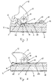
- each of the clamping devices 5 has a clamping lever 8, the distance from the back 7 of the vibrating plate 2 an axis 9 is pivotally mounted, which is parallel to the narrow surface side 4 of the oscillating plate 2 extends.
- the Axis 9 is located on a bearing block 10 which on the Back 7 of the vibrating plate 2 protrudes upwards.
- the clamping lever 8 has on that side of the axis 9 that to the narrow surface side 4 of the oscillating plate 2 on the underside a shape like a protrusion Heel with a clamping surface 11 on the underside, which is flat and which is under tension of the edge area of the any existing abrasive sheet 6 against a flat Counter surface on the back 7 of the vibrating plate 2 elastic is pressed.
- the clamping lever 8 pivoted about the axis 9 via an actuating element 12 be that the clamping surface 11 from the clamping counter surface on the back 7 of the vibrating plate 2.
- the actuating element 12 is designed in the manner of a nose, the approximately in the radial direction to the pivot axis 9 am Clamping lever 8 protrudes. Based on the pivot axis 9 is located the actuator 12 on the same side of the clamping lever 8 as its clamping surface 11. Has a total the clamping lever 8 has a compact shape, making its lever arms are not very pronounced.
- the Cam contour 14 has an apex area that is parallel extends to the pivot axis 9. Points in the crown area the cam contour 14 has a clear curve to which one first edge 15 of the cam contour 14 connects. On the opposite Page beyond one explained below The cam contour goes to the dead center in the apex area 14 into a second flank 16 and the two flanks 15 and 16 of the cam contour 14 serve as engagement surfaces for the spring 13, depending on whether the clamping lever 8 in the clamping position or in the open position.
- the under Preload on the cam contour 14 or on its flanks 15 or 16 is present.
- the bias of the leaf spring 13 is accordingly in such a way that it deals with its Clamping lever 8 adjacent section from the rear 7 of the Tried to move vibrating plate 2 upwards.
- one of the flanks 15 or 16 of the cam contour 14 is also in this position tensioned leaf spring 13 in substantially parallel to the back 7 of the vibrating plate 2 aligned. Only when swiveling the clamping lever 8 from its clamping position to its open position Driving over the apex area of the cam contour 14, the a greater distance from the pivot axis 9 than the two Flanks 15, 16, the leaf spring 13 in the direction of Back 7 of the vibrating plate 2 deflected out.
- the spring 13 is clamped at one end Leaf spring.
- the spring 13 is on top of the Back 7 of the vibrating plate 2 protruding paragraph 18 placed and attached to it with a screw.
- the free end 17 of the spring 13 engages under the clamping lever 8 in whose clamping position, which is shown in Fig. 2, in the area the first edge 15.
- the edge 15 of the cam contour 14 is substantially flat and is parallel to that Clamping surface 11 on the clamping lever 8.
- the point of application of the spring 13 or the spring end 17 lies on the first flank 15, as far as the clamping position of the clamping lever 8 is concerned, near the apex area of the cam contour 14.
- first flank 15 of the cam contour 14 is preferred spherical and goes continuously into the convex curve the apex region of the cam contour 14 over.
- the on the other side beyond dead center second flank 16 of the cam contour adjoining the apex region 14 on the clamping lever 8 is continuously flat.
- the clamping surface 11 lies in relation to the pivot axis 9 and the actuator 12 on one side of the Clamping lever 8 and the raised cam contour 14 on the opposite side of the clamping lever 8, wherein the distance of the pivot axis 9 to the cam contour 14 towards those Forms lever arm on which the spring 13 engages and when resting on the flank 15, the clamping lever 8 in the direction who tries to swivel the direction of rotation. This will make the elastic clamping force for clamping the abrasive sheet 6 applied to the clamping surface 11 of the clamping lever 8.
- the spring 13 is also designed as a leaf spring.
- the feather is 13 supported here on both ends, and the supports 21, 22 are through recesses in the rear 7 of the oscillating plate 2 educated.
- the spring 13 acts on the cam contour 14 of the Clamping lever 8 in a hollow area, this is between the supports 21 and 22 on the back 7 of the Swing plate 2 a recessed free space 23 is provided.
- the in the direction of the cam contour 14 of the clamping lever 8 Prestressed spring 13 can consequently deflect through the cam contour 14 when pivoting the clamping lever 8 lower into the free space 23, thereby blocking the spring 13 is avoided.
- FIG. 4 While in the embodiment of FIG. 4, the longitudinal direction the leaf spring 13 perpendicular to the vertical radial plane runs through the pivot axis 9, lies in the embodiment of FIG. 4 which also here Leaf spring designed spring 13 substantially parallel to the pivot axis 9.
- the spring 13 is seated in a recess 30 on the back 7 of the vibrating plate 2 and has one for Clamping lever 8 protruding curvature section 29, with appropriate preload, the cam contour 14 on the clamping lever 8 engages.
- the clamping lever 8 of its clamping position in the open position will be the Curvature 29 of the spring 13 elastically deformed.
- the clamping lever 8 has a protruding Cam contour 24 with flanks 25 and 26 with which it under spring tension, however, directly on the rear 7 the vibrating plate 2 is seated at the relevant point forms an abutment 28 in the form of a flat surface, on which the clamping lever 8 slide with its cam contour 24 can.
- the clamping lever 8 In the clamping position, the clamping lever 8 is supported with the first flank 25 of its cam contour 24 with its apex region, the one relative to the cam flanks 25, 26 has a greater distance from the pivot axis 27 on the abutment 28 from the rear 7 of the oscillating plate 2.
- the second flank 26 is in the open position the abutment 28 on the rear 7 of the oscillating plate 2 on, so that here, too, analogous to those explained above Embodiments of the clamping lever 8 in its open position kept free of play and on the other hand in its clamping position is loaded with a clamping torque.
- the bending line B of the pivot axis 27 is elastic swung out position for illustration with shown an exaggerated curvature. You can tell by that however, it is particularly good that the pivot axis 27 due to its Spring force strives to counteract its deflection towards the abutment 28 on the rear 7 of the To reset the vibrating plate 2. This will make the cam contour 24 on the clamping lever 8 with their flanks 25 and 26 constantly held on the abutment 28.
Landscapes
- Engineering & Computer Science (AREA)
- Mechanical Engineering (AREA)
- Finish Polishing, Edge Sharpening, And Grinding By Specific Grinding Devices (AREA)
- Clamps And Clips (AREA)
- Jigs For Machine Tools (AREA)
Abstract
Description
- Fig. 1
- die Seitansicht eines Hand-Schwingschleifers mit einem teilgeschnittenen Bereich seiner Schwingplatte,
- Fig. 2
- in vergrößerter Darstellung einen Schnitt durch den einen Endbereich der Schwingplatte des Schwingschleifers nach Fig. 1 mit der daran befindlichen Spannvorrichtung, bei der sich deren Klemmhebel in der Spannlage befindet,
- Fig. 3
- eine der Fig. 2 entsprechende Darstellung, bei der sich der Klemmhebel der Spannvorrichtung in angekippter Totpunktlage befindet,
- Fig. 4
- eine der Fig. 2 entsprechende Darstellung mit einer den Klemmhebel der Spannvorrichtung beaufschlagenden Feder in zweiter Ausführung,
- Fig. 5
- eine der Fig. 2 entsprechende Darstellung jedoch mit einer den Klemmhebel der Spannvorrichtung beaufschlagenden Feder in dritter Ausführung,
- Fig. 6
- eine der Fig. 2 entsprechende Darstellung, jedoch mit einer völlig anders gestalteten Feder zur Beaufschlagung des Klemmhebels der Spannvorrichtung in Richtung der Spannlage und
- Fig. 7
- einen Schnitt durch die Spannvorrichtung nach Fig. 6 entlang der Linie A-A.
Claims (15)
- Spannvorrichtung an der Rückseite der Schwingplatte (2) eines Hand-Schwingschleifers zum lösbaren Halten eines um eine benachbarte Schmalseite der Schwingplatte (2) mit einem Randbereich herumgelegten Schleifmittelblattes (6) bestehend aus einem um eine mit der Schwingplattenrückseite (7) parallele Achse (9) schwenkbaren Klemmhebel (8), der an seiner der Schwingplatten-Schmalseite zugewandten Seite eine unter Zwischenfügen des Randbereichs des Schleifmittelblattes (6) gegen die Schwingplattenrückseite (7) spannbare Klemmfläche oder -kante (11) hat und der zumindest in seiner Spannlage von einer die Klemmkraft aufbringenden Feder (13) beaufschlagt ist und der ferner ein von Hand bedienbares Betätigungselement (12) zum Verschwenken aus seiner Spannlage heraus in eine die Klemmfläche (11) von der Schwingplattenrückseite (7) abgehobene Offenstellung hat,
dadurch gekennzeichnet, daß der Klemmhebel (8) eine erhabene Kontur (14) nach Art eines Nockens hat,
daß diese Kontur (14) anschließend an einen Scheitelbereich mit einem Totpunkt, der den größten Abstand von der Schwenkachse (9) hat und an dem die Feder (13) ein Drehmoment auf den Klemmhebel (8) nicht ausüben kann, eine erste Flanke (15) hat, bei deren Beaufschlagung durch die Feder (13) ein Drehmoment in Spanndrehrichtung auf den Klemmhebel (8) ausgeübt wird,
und daß die Kontur (14) des Klemmhebels (8) eine zweite Flanke (16) aufweist, die jenseits des Scheitelbereichs der ersten Flanke (15) gegenüberliegt und bei deren Beaufschlagung durch die Feder (13) auf den Klemmhebel (8) ein Drehmoment entgegen der Spanndrehrichtung ausgeübt wird. - Spannvorrichtung nach Anspruch 1,
dadurch gekennzeichnet, daß die Feder (13) eine Blattfeder ist, die mit einer ihrer Breitseiten mit Vorspannung an der erhabenen Nockenkontur (14) am Klemmhebel (8) bzw. an deren Flanken (15, 16) anliegt. - Spannvorrichtung nach Anspruch 1 oder 2,
dadurch gekennzeichnet, daß die erhabene Nockenkontur (14) am Klemmhebel (8) eine konvexe Rundung aufweist und zumindest die erste Flanke (15) in diese Rundung mit einem stetigen Verlauf übergeht. - Spannvorrichtung nach Anspruch 2 oder 3,
dadurch gekennzeichnet, daß die zweite Flanke (16) im an den Scheitelbereich der Nockenkontur (14) am Klemmhebel (8) anschließenden Bereich eben ist. - Spannvorrichtung nach einem der Ansprüche 3 und 4,
dadurch gekennzeichnet, daß die erste Flanke (15) der Nockenkontur (14) am Klemmhebel (8) mit ihrem gerundeten Bereich an einen ebenen Bereich (15a) anschließt und der Winkel zwischen diesem ebenen Bereich (15a) und der zweiten Flanke (16) der Nockenkontur (14) größer als der Schwenkwinkel des Klemmhebels (8) zwischen dessen Spannlage und dessen Offenstellung ist. - Spannvorrichtung nach Anspruch 5,
dadurch gekennzeichnet, daß der Winkel zwischen dem ebenen Bereich (15a) der ersten Flanke (15) und der zweiten Flanke (16) der Nockenkontur (14) am Klemmhebel (8) wenigstens 90 Grad beträgt. - Spannvorrichtung nach einem der Ansprüche 3 bis 6,
dadurch gekennzeichnet, daß die Klemmfläche (11) am Klemmhebel (8) eben ist und der ebene Bereich (15a) der ersten Flanke (15) der Nockenkontur (14) am Klemmhebel (8) mit der Klemmfläche (11) ebenengleich oder parallel zu der Klemmfläche (11) ist. - Spannvorrichtung nach einem der Ansprüche 2 bis 7,
dadurch gekennzeichnet, daß die Feder (13) eine einendig eingespannte Blattfeder ist, die mit ihrem freien Ende (17) unter Vorspannung an der Nockenkontur (14) bzw. an deren Flanken (15, 16) anliegt. - Spannvorrichtung nach Anspruch 8,
dadurch gekennzeichnet, daß die Feder (13) in Abstand von dem Klemmhebel (8) an der Rückseite (7) der Schwingplatte (2) eingespannt ist. - Spannvorrichtung nach Anspruch 9,
dadurch gekennzeichnet, daß die vorgespannte, an den Flanken (15, 16) der Nockenkontur (14) am Klemmhebel (8) anliegende Feder (13) sich parallel oder nahezu parallel zur Schwingplattenrückseite (7) erstreckt. - Spannvorrichtung nach Anspruch 10,
dadurch gekennzeichnet, daß an der Schwingplattenrückseite (7) eine Tasche (20) zur Aufnahme des durch die Nockenkontur (14) am Klemmhebel (8) ausgelenkten Endes (17) der Feder (13) angeordnet ist. - Spannvorrichtung nach einem der Ansprüche 2 bis 7,
dadurch gekennzeichnet, daß die Feder (13) eine an der Schwingplattenrückseite (7) beidendig aufgelagerte Blattfeder ist, die mit ihrem zwischen den Auflagern (21, 22) befindlichen Bereich mit Vorspannung an der Nockenkontur (14) bzw. an deren Flanken (15, 16) anliegt, wobei zwischen den Auflagern (21, 22) ein Freiraum (23) zur Aufnahme des durch die Nockenkontur (14) am Klemmhebel (8) ausgelenkten Federbereichs besteht. - Spannvorrichtung nach Anspruch 12,
dadurch gekennzeichnet, daß die Feder (13) in ihrem Anlagebereich zwischen den Auflagern (21, 22) zum Klemmhebel (8) hin vorgewölbt ist. - Spannvorrichtung an der Rückseite der Schwingplatte (2) eines Hand-Schwingschleifers zum lösbaren Halten eines um eine Schmalseite der Schwingplatte (2) herumgelegten Schleifmittelblattes (6) bestehend aus einem um eine mit der Schwingplattenrückseite (7) parallele Achse (9) schwenkbaren Klemmhebel (8), der an seiner der Schwingplatten-Schmalseite zugewandten Seite eine unter Zwischenfügen des Randes des Schleifmittelblattes (6) gegen die Schwingplattenrückseite (7) spannbare Klemmfläche oder -kante (11) hat und der zumindest in seiner Klemmlage von einer die Spannkraft aufbringenden Feder (13) beaufschlagt ist und der ferner ein von Hand bedienbares Betätigungselement (12) zum Verschwenken aus seiner Spannlage heraus in eine die Klemmfläche (11) von der Schwingplattenrückseite (7) abhebende Offenstellung hat,
dadurch gekennzeichnet, daß der Klemmhebel (8) eine erhaben vorstehende Nockenkontur (24) mit einem Scheitelbereich hat, der den größten Abstand von der Schwenkachse (27) aufweist, an den eine erste Flanke (25) und eine zweite Flanke (26) anschließt, daß die Schwenkachse (27) biegeelastisch ist und mit entsprechender Biegevorspannung zur Schwingplattenrückseite (7) hin die Feder bildet und daß sich der Klemmhebel (8) in der Spannlage sowohl mit seiner Klemmfläche (11) an der Schwingplattenrückseite (7) als auch mit der ersten Flanke (25) seiner Nockenkontur (24) an einem Widerlager (28) an der Schwingplattenrückseite (7) unter Erzeugung eines Drehmomentes in Spanndrehrichtung abstützt und in der Offenstellung nur mit der zweiten Flanke (26) seiner Nockenkontur (24) an diesem Widerlager (28) verschwenksicher abgestützt ist. - Spannvorrichtung nach Anspruch 11,
dadurch gekennzeichnet, daß die Nockenkontur (24) eine konvexe, in die Flanken (25, 26) übergehende Rundung aufweist.
Applications Claiming Priority (2)
| Application Number | Priority Date | Filing Date | Title |
|---|---|---|---|
| DE10058610A DE10058610B4 (de) | 2000-11-25 | 2000-11-25 | Spannvorrichtung an einem Schwingschleifer zum Halten des Schleifmittelblattes |
| DE10058610 | 2000-11-25 |
Publications (4)
| Publication Number | Publication Date |
|---|---|
| EP1211022A2 true EP1211022A2 (de) | 2002-06-05 |
| EP1211022A3 EP1211022A3 (de) | 2004-01-21 |
| EP1211022B1 EP1211022B1 (de) | 2005-06-08 |
| EP1211022B8 EP1211022B8 (de) | 2005-08-10 |
Family
ID=7664674
Family Applications (1)
| Application Number | Title | Priority Date | Filing Date |
|---|---|---|---|
| EP01127816A Expired - Lifetime EP1211022B8 (de) | 2000-11-25 | 2001-11-22 | Spannvorrichtung an einem Schwingschleifer zum Halten des Schleifmittelblattes |
Country Status (4)
| Country | Link |
|---|---|
| EP (1) | EP1211022B8 (de) |
| AT (1) | ATE297290T1 (de) |
| DE (2) | DE10058610B4 (de) |
| ES (1) | ES2241734T3 (de) |
Family Cites Families (11)
| Publication number | Priority date | Publication date | Assignee | Title |
|---|---|---|---|---|
| US2242545A (en) * | 1940-03-27 | 1941-05-20 | Sundstrand Machine Tool Co | Rubbing machine |
| US2712209A (en) * | 1950-08-28 | 1955-07-05 | Pillsbury Mills Inc | Process of and apparatus for sealing receptacles |
| US2712206A (en) * | 1952-06-16 | 1955-07-05 | Roy J Champayne | Rubbing shoe |
| US2914889A (en) * | 1955-07-28 | 1959-12-01 | Sundstrand Corp | Clamping device |
| US2918761A (en) * | 1957-04-24 | 1959-12-29 | Sundstrand Corp | Rubbing machine |
| DE2511392C2 (de) * | 1975-03-15 | 1982-09-23 | Robert Bosch Gmbh, 7000 Stuttgart | Schwingschleifer mit Staubabsaugung |
| US4030254A (en) * | 1976-03-05 | 1977-06-21 | Chicago Pneumatic Tool Company | Sanding shoe with removable clamping jaw |
| DE2832424C2 (de) * | 1978-07-24 | 1982-05-06 | Licentia Patent-Verwaltungs-Gmbh, 6000 Frankfurt | Handschwingschleifmaschine |
| JPH0215256U (de) * | 1988-07-01 | 1990-01-30 | ||
| DE4037266A1 (de) * | 1990-11-23 | 1992-05-27 | Bosch Gmbh Robert | Vorrichtung zum festspannen von schleifpapier an einem schwingschleifer |
| DE19800044A1 (de) * | 1997-02-27 | 1998-09-03 | Bosch Gmbh Robert | Elektrohandwerkzeug, insbesondere Schleifgerät |
-
2000
- 2000-11-25 DE DE10058610A patent/DE10058610B4/de not_active Expired - Fee Related
-
2001
- 2001-11-22 EP EP01127816A patent/EP1211022B8/de not_active Expired - Lifetime
- 2001-11-22 AT AT01127816T patent/ATE297290T1/de not_active IP Right Cessation
- 2001-11-22 ES ES01127816T patent/ES2241734T3/es not_active Expired - Lifetime
- 2001-11-22 DE DE50106441T patent/DE50106441D1/de not_active Expired - Lifetime
Also Published As
| Publication number | Publication date |
|---|---|
| EP1211022B1 (de) | 2005-06-08 |
| DE50106441D1 (de) | 2005-07-14 |
| EP1211022B8 (de) | 2005-08-10 |
| ATE297290T1 (de) | 2005-06-15 |
| EP1211022A3 (de) | 2004-01-21 |
| DE10058610A1 (de) | 2002-06-06 |
| DE10058610B4 (de) | 2005-12-08 |
| ES2241734T3 (es) | 2005-11-01 |
Similar Documents
| Publication | Publication Date | Title |
|---|---|---|
| DE3905600C2 (de) | Verfahren zum Schneiden von Papier sowie Papierschneidemaschine | |
| EP1157653B1 (de) | Halter zur Befestigung eines Wischmops am Ende eines Stiels | |
| DE2636505C2 (de) | Messerscheide mit Schärfvorrichtung | |
| EP1527728B1 (de) | Flächenreinigungsgerät | |
| CH637564A5 (de) | Rasierapparat. | |
| DE3814554A1 (de) | Schneidmesser | |
| EP0416358B1 (de) | Rasierapparatekopf eines Nassrasierapparates | |
| DE3043606C2 (de) | Spannvorrichtung, insbesondere Schraubstock | |
| EP0396890A1 (de) | Vorrichtung zum Reinigen von Förderbändern | |
| EP1722928B1 (de) | Einhandspannzwinge | |
| DE3217051A1 (de) | Vorrichtung zur laengsverstellung von skibindungsteilen | |
| DE60013617T2 (de) | Einhändig handhabbare, einstellbare zange | |
| DE1553846B2 (de) | Scherenaehnliches handwerkzeug | |
| DE2435591C3 (de) | Handschleifmaschine | |
| EP0103319B1 (de) | Presswerkzeug vom Zangentyp | |
| DE10058610B4 (de) | Spannvorrichtung an einem Schwingschleifer zum Halten des Schleifmittelblattes | |
| DE4128887A1 (de) | Gripzange | |
| CH695099A5 (de) | Spannvorrichtung, insbesondere für handgeführte Elektrowerkzeuge. | |
| DE4037266A1 (de) | Vorrichtung zum festspannen von schleifpapier an einem schwingschleifer | |
| DE3637985C2 (de) | Biegestanze | |
| DE3426241A1 (de) | Abgesetzte allzweck-blechschere mit einem drahtschneider | |
| DE4108690C2 (de) | Schnittlaufzange | |
| DE102010020655A1 (de) | Wasserpumpenzange | |
| DE2736671C3 (de) | Werkzeug zum Auftragen von Kittmaterial entlang einer Wandecke | |
| DE1193834B (de) | Einstellbare Haarschneidemaschine |
Legal Events
| Date | Code | Title | Description |
|---|---|---|---|
| PUAI | Public reference made under article 153(3) epc to a published international application that has entered the european phase |
Free format text: ORIGINAL CODE: 0009012 |
|
| AK | Designated contracting states |
Kind code of ref document: A2 Designated state(s): AT BE CH CY DE DK ES FI FR GB GR IE IT LI LU MC NL PT SE TR |
|
| AX | Request for extension of the european patent |
Free format text: AL;LT;LV;MK;RO;SI |
|
| PUAL | Search report despatched |
Free format text: ORIGINAL CODE: 0009013 |
|
| AK | Designated contracting states |
Kind code of ref document: A3 Designated state(s): AT BE CH CY DE DK ES FI FR GB GR IE IT LI LU MC NL PT SE TR |
|
| AX | Request for extension of the european patent |
Extension state: AL LT LV MK RO SI |
|
| 17P | Request for examination filed |
Effective date: 20040701 |
|
| AKX | Designation fees paid |
Designated state(s): AT CH DE ES FR GB IT LI |
|
| GRAP | Despatch of communication of intention to grant a patent |
Free format text: ORIGINAL CODE: EPIDOSNIGR1 |
|
| GRAS | Grant fee paid |
Free format text: ORIGINAL CODE: EPIDOSNIGR3 |
|
| GRAA | (expected) grant |
Free format text: ORIGINAL CODE: 0009210 |
|
| AK | Designated contracting states |
Kind code of ref document: B1 Designated state(s): AT CH DE ES FR GB IT LI |
|
| REG | Reference to a national code |
Ref country code: GB Ref legal event code: FG4D Free format text: NOT ENGLISH |
|
| REG | Reference to a national code |
Ref country code: CH Ref legal event code: EP |
|
| RAP2 | Party data changed (patent owner data changed or rights of a patent transferred) |
Owner name: METABOWERKE GMBH |
|
| REF | Corresponds to: |
Ref document number: 50106441 Country of ref document: DE Date of ref document: 20050714 Kind code of ref document: P |
|
| REG | Reference to a national code |
Ref country code: CH Ref legal event code: NV Representative=s name: SCHMAUDER & PARTNER AG PATENTANWALTSBUERO |
|
| GBT | Gb: translation of ep patent filed (gb section 77(6)(a)/1977) |
Effective date: 20050727 |
|
| REG | Reference to a national code |
Ref country code: ES Ref legal event code: FG2A Ref document number: 2241734 Country of ref document: ES Kind code of ref document: T3 |
|
| ET | Fr: translation filed | ||
| PLBE | No opposition filed within time limit |
Free format text: ORIGINAL CODE: 0009261 |
|
| STAA | Information on the status of an ep patent application or granted ep patent |
Free format text: STATUS: NO OPPOSITION FILED WITHIN TIME LIMIT |
|
| 26N | No opposition filed |
Effective date: 20060309 |
|
| REG | Reference to a national code |
Ref country code: CH Ref legal event code: PCAR Free format text: SCHMAUDER & PARTNER AG PATENT- UND MARKENANWAELTE VSP;ZWAENGIWEG 7;8038 ZUERICH (CH) |
|
| PGFP | Annual fee paid to national office [announced via postgrant information from national office to epo] |
Ref country code: AT Payment date: 20091120 Year of fee payment: 9 Ref country code: CH Payment date: 20091124 Year of fee payment: 9 Ref country code: ES Payment date: 20091123 Year of fee payment: 9 |
|
| REG | Reference to a national code |
Ref country code: CH Ref legal event code: PL |
|
| PG25 | Lapsed in a contracting state [announced via postgrant information from national office to epo] |
Ref country code: LI Free format text: LAPSE BECAUSE OF NON-PAYMENT OF DUE FEES Effective date: 20101130 Ref country code: CH Free format text: LAPSE BECAUSE OF NON-PAYMENT OF DUE FEES Effective date: 20101130 |
|
| PG25 | Lapsed in a contracting state [announced via postgrant information from national office to epo] |
Ref country code: AT Free format text: LAPSE BECAUSE OF NON-PAYMENT OF DUE FEES Effective date: 20101122 |
|
| REG | Reference to a national code |
Ref country code: ES Ref legal event code: FD2A Effective date: 20120110 |
|
| PG25 | Lapsed in a contracting state [announced via postgrant information from national office to epo] |
Ref country code: ES Free format text: LAPSE BECAUSE OF NON-PAYMENT OF DUE FEES Effective date: 20101123 |
|
| REG | Reference to a national code |
Ref country code: DE Ref legal event code: R082 Ref document number: 50106441 Country of ref document: DE Representative=s name: LORENZ & KOLLEGEN PATENTANWAELTE PARTNERSCHAFT, DE |
|
| REG | Reference to a national code |
Ref country code: FR Ref legal event code: PLFP Year of fee payment: 15 |
|
| PGFP | Annual fee paid to national office [announced via postgrant information from national office to epo] |
Ref country code: IT Payment date: 20151124 Year of fee payment: 15 Ref country code: GB Payment date: 20151123 Year of fee payment: 15 Ref country code: DE Payment date: 20151119 Year of fee payment: 15 |
|
| PGFP | Annual fee paid to national office [announced via postgrant information from national office to epo] |
Ref country code: FR Payment date: 20151124 Year of fee payment: 15 |
|
| REG | Reference to a national code |
Ref country code: DE Ref legal event code: R119 Ref document number: 50106441 Country of ref document: DE |
|
| GBPC | Gb: european patent ceased through non-payment of renewal fee |
Effective date: 20161122 |
|
| REG | Reference to a national code |
Ref country code: FR Ref legal event code: ST Effective date: 20170731 |
|
| PG25 | Lapsed in a contracting state [announced via postgrant information from national office to epo] |
Ref country code: FR Free format text: LAPSE BECAUSE OF NON-PAYMENT OF DUE FEES Effective date: 20161130 Ref country code: IT Free format text: LAPSE BECAUSE OF NON-PAYMENT OF DUE FEES Effective date: 20161122 |
|
| PG25 | Lapsed in a contracting state [announced via postgrant information from national office to epo] |
Ref country code: DE Free format text: LAPSE BECAUSE OF NON-PAYMENT OF DUE FEES Effective date: 20170601 Ref country code: GB Free format text: LAPSE BECAUSE OF NON-PAYMENT OF DUE FEES Effective date: 20161122 |