EP1210532B1 - Planetengetriebe mit lastausgleich - Google Patents
Planetengetriebe mit lastausgleich Download PDFInfo
- Publication number
- EP1210532B1 EP1210532B1 EP00968311A EP00968311A EP1210532B1 EP 1210532 B1 EP1210532 B1 EP 1210532B1 EP 00968311 A EP00968311 A EP 00968311A EP 00968311 A EP00968311 A EP 00968311A EP 1210532 B1 EP1210532 B1 EP 1210532B1
- Authority
- EP
- European Patent Office
- Prior art keywords
- sun gear
- gear
- planet gears
- helical cut
- transmission housing
- Prior art date
- Legal status (The legal status is an assumption and is not a legal conclusion. Google has not performed a legal analysis and makes no representation as to the accuracy of the status listed.)
- Expired - Lifetime
Links
- 230000005540 biological transmission Effects 0.000 title claims abstract description 178
- 230000003993 interaction Effects 0.000 description 4
- 238000004519 manufacturing process Methods 0.000 description 4
- 230000007246 mechanism Effects 0.000 description 3
- 230000004044 response Effects 0.000 description 3
- 125000006850 spacer group Chemical group 0.000 description 3
- 230000008901 benefit Effects 0.000 description 2
- 230000004048 modification Effects 0.000 description 2
- 238000012986 modification Methods 0.000 description 2
- 238000013459 approach Methods 0.000 description 1
- 238000003754 machining Methods 0.000 description 1
- 230000013011 mating Effects 0.000 description 1
- 230000002028 premature Effects 0.000 description 1
- 230000000284 resting effect Effects 0.000 description 1
Images


Classifications
-
- F—MECHANICAL ENGINEERING; LIGHTING; HEATING; WEAPONS; BLASTING
- F16—ENGINEERING ELEMENTS AND UNITS; GENERAL MEASURES FOR PRODUCING AND MAINTAINING EFFECTIVE FUNCTIONING OF MACHINES OR INSTALLATIONS; THERMAL INSULATION IN GENERAL
- F16H—GEARING
- F16H1/00—Toothed gearings for conveying rotary motion
- F16H1/28—Toothed gearings for conveying rotary motion with gears having orbital motion
- F16H1/2809—Toothed gearings for conveying rotary motion with gears having orbital motion with means for equalising the distribution of load on the planet-wheels
- F16H1/2818—Toothed gearings for conveying rotary motion with gears having orbital motion with means for equalising the distribution of load on the planet-wheels by allowing limited movement of the ring gear relative to the casing or shaft
-
- F—MECHANICAL ENGINEERING; LIGHTING; HEATING; WEAPONS; BLASTING
- F16—ENGINEERING ELEMENTS AND UNITS; GENERAL MEASURES FOR PRODUCING AND MAINTAINING EFFECTIVE FUNCTIONING OF MACHINES OR INSTALLATIONS; THERMAL INSULATION IN GENERAL
- F16H—GEARING
- F16H1/00—Toothed gearings for conveying rotary motion
- F16H1/28—Toothed gearings for conveying rotary motion with gears having orbital motion
- F16H1/2809—Toothed gearings for conveying rotary motion with gears having orbital motion with means for equalising the distribution of load on the planet-wheels
- F16H1/2845—Toothed gearings for conveying rotary motion with gears having orbital motion with means for equalising the distribution of load on the planet-wheels by allowing limited movement of the sun gear
-
- F—MECHANICAL ENGINEERING; LIGHTING; HEATING; WEAPONS; BLASTING
- F16—ENGINEERING ELEMENTS AND UNITS; GENERAL MEASURES FOR PRODUCING AND MAINTAINING EFFECTIVE FUNCTIONING OF MACHINES OR INSTALLATIONS; THERMAL INSULATION IN GENERAL
- F16H—GEARING
- F16H1/00—Toothed gearings for conveying rotary motion
- F16H1/28—Toothed gearings for conveying rotary motion with gears having orbital motion
- F16H1/46—Systems consisting of a plurality of gear trains each with orbital gears, i.e. systems having three or more central gears
-
- F—MECHANICAL ENGINEERING; LIGHTING; HEATING; WEAPONS; BLASTING
- F16—ENGINEERING ELEMENTS AND UNITS; GENERAL MEASURES FOR PRODUCING AND MAINTAINING EFFECTIVE FUNCTIONING OF MACHINES OR INSTALLATIONS; THERMAL INSULATION IN GENERAL
- F16H—GEARING
- F16H1/00—Toothed gearings for conveying rotary motion
- F16H1/28—Toothed gearings for conveying rotary motion with gears having orbital motion
- F16H2001/289—Toothed gearings for conveying rotary motion with gears having orbital motion comprising two or more coaxial and identical sets of orbital gears, e.g. for distributing torque between the coaxial sets
-
- F—MECHANICAL ENGINEERING; LIGHTING; HEATING; WEAPONS; BLASTING
- F16—ENGINEERING ELEMENTS AND UNITS; GENERAL MEASURES FOR PRODUCING AND MAINTAINING EFFECTIVE FUNCTIONING OF MACHINES OR INSTALLATIONS; THERMAL INSULATION IN GENERAL
- F16H—GEARING
- F16H57/00—General details of gearing
- F16H57/02—Gearboxes; Mounting gearing therein
- F16H57/033—Series gearboxes, e.g. gearboxes based on the same design being available in different sizes or gearboxes using a combination of several standardised units
Definitions
- the present invention is directed to improvements in planetary transmissions. More particularly, the present invention is directed to planetary gear transmissions having multiple planetary gear sets employing helical cut gears for providing power sharing amongst the planetary gear sets.
- Planetary gear trains have the advantage over pinion type gearing by permitting higher power densities, large gear ratios, and concentric power input and output. Increased power requirements in planetary gear trains are usually accommodated by increasing the diameter and width of the gears. If there are restrictions on the diametrical size of the gear train, increases in power can be met only by increasing the width of the gears or upping the material and machining specifications. There are practical limits to both these approaches.
- Gear transmissions having pairs of helical gears mounted on a drive shaft for engagement with respective pairs of helical gears mounted on a driven shaft are disclosed in copending United States Patent Application Serial No. 09/167,760 filed October 7, 1998 entitled Improvements In Power Sharing Gear Sets.
- the disclosures, including the disclosures of the specification and drawings, of prior United States Patent Application Serial No. 09/167,760 filed October 7, 1998 are hereby expressly incorporated by reference into this present application.
- the use of paired helical gears in multi-speed automotive transmissions is disclosed in U.S. Patent Application Serial No. 09/187,905 filed November 6, 1998 entitled Multi-Speed Automotive Transmission Using Paired Helical Gearing.
- the disclosures, including the disclosures of the specification and drawings, of prior United States Patent Application Serial No. 09/187,905 filed November 6, 1998 are hereby expressly incorporated by reference into this present application.
- US 4391163 which shows the features of the preamble of claims 1 and 6 describes the planetary gear assembly having a housing with an input shaft rotatably mounted therein.
- the shaft supports a central gear which includes two axially spaced helical gear portions which mesh with oppositely helically geared rotatably planetary gears.
- the gears are fixed to the shaft with antifriction bearings so as to be rotatable and radially fixed in position.
- a pair of planet wheels mesh with the double helical inner central gear and have oppositely directed helical-gearings to engage with the corresponding helical portions of outer central gears which are secured to the housing.
- US 3459072 which shows the features of the preamble of claim 4 has described another example of epicyclic gearing having double helical gears.
- the gearing comprises a southern wheel, planet wheels and an annulus in which the southern wheel is carried on an input shaft and meshes with the planet wheel mounted on a planet wheel carrier.
- the planet wheel carrier is secured to a hub member rotating in a bearing and secured to the output shaft.
- the planet wheels mesh with the annulus, which is stationary.
- the present invention is directed to a planetary gear transmission having multiple planetary gear sets employing helical cut gears.
- Each planetary gear set in the gear train comprises a sun gear mounted on a sun shaft with the sun gear engaging a plurality of planet gears mounted in a planet gear carrier with the plurality of planet gears engaging a ring gear mounted on the transmission housing.
- the planet gear carrier may be the drive member with the sun shaft being the driven member.
- the sun shaft may be the drive member with the planet gear carrier being the driven member.
- the planetary gear transmission of the present invention employs helical cut gears for the sun gears, ring gears, and planet gears of the planetary gear sets to obtain practical balanced power sharing and load between two or more planetary gear sets in the gear train.
- Helical gears due to the helical angle of the gear cut, experience axial thrust when loaded.
- the magnitude of this axial thrust is directly proportional to the torque load on the gear.
- Power sharing and balanced load between planetary gear sets of the planetary gear transmission of the present invention is achieved by employing this axial thrust reaction and the resulting axial movement of sun gears and/or ring gears of adjacent planetary gear sets wherein sun gears and/or ring gears of adjacent planetary gear sets are mounted for axial movement with respect to the planetary transmission housing. If one of the planetary gear sets is more heavily loaded than the others, the axial thrust on the helical sun gear and helical ring gear of that set is not balanced with the axial thrust loads on the other planetary gear sets. The sun gear and/or the ring gear that is more heavily loaded, and thus experiencing a greater axial thrust load, moves axially in response to this thrust imbalance so as to achieve equal load sharing between planetary gear sets and no axial thrust imbalances.
- the planet gears do not move axially during the operation of the planetary gear transmission.
- the axial thrust on a given planet gear due to interaction with a respective sun gear is equal and opposite to the axial thrust due to interaction with a respective ring gear. Therefore, the axial forces acting on a planet gear are equal and opposite resulting in no tendency for planet gears to move axially.
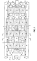
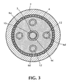
- a planetary gear train with four planetary gear sets is illustrated in accordance with one embodiment of the present invention. It should be understood that the present invention may be practiced with two planetary gear sets or a plurality of planetary of planetary gear sets.
- planet gear carrier 4 is mounted by bearings 6a, which may be, e.g., needle type bearings or roller bearings, in cylindrical transmission housing 7.
- Planet gear sets 2a, 2b, 2c, and 2d each comprise planet gears which are mounted for rotation in planet gear carrier 4.
- Planet gear carrier 4 holds planet gear sets 2a, 2b, 2c, and 2d in fixed relationship to one another. All the planet gears are free to turn or rotate independently of one another.
- each planet gear has two planet shafts 12 which are received by a respective bore in planet gear holder 4 and the rotational mounting is accomplished by means, e.g., of journal bearings 6d.
- each planet gear and its associated planet gear shafts 12 would be an integral member machined from a common stock material.
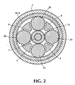
- Planet gears 2a, 2b, 2c and 2d all have helical cut gear teeth.
- the helical cut of planet gears 2a (four in number as shown in the embodiment illustrated in Fig. 2 ) has a sense or hand and an angle with respect to the axial center line of the gear which is the same for each planet gear 2a.
- the helical cut for planet gears 2b has a sense or hand and an angle with respect to the axial center line of the gear which is the same for each planet gear 2b, but which is opposite to the sense or hand and angle of the helical cut of planet gears 2a.
- the helical cut for planet gears 2c has a sense or a hand and an angle with respect to the axial center line of the gear which is the same for each planet gear 2c, but which is opposite to the sense or hand and angle of the helical cut of planet gears 2b.
- the sense or hand and the angle of the helical cut of planet gears 2c are the same as the sense or hand and angle of the helical cut of planet gears 2a.
- the helical cut for planet gears 2d has a sense or a hand and an angle with respect to the axial center line of the gear which is the same for each planet gear 2d, but which is opposite to the sense or the hand and angle of the helical cut of planet gears 2c.
- Cylindrical transmission housing 7 has a longitudinal central axis 20.
- Planet gear carrier 4 has a longitudinal central axis which is parallel to and coincident with the longitudinal central axis 20 of cylindrical transmission housing 7.
- the planet gears are mounted for rotation in planet gear carrier 4 by shafts 12 and bearings 6d in a manner which substantially prevents, during operation, movement of the planet gears in the direction of the longitudinal central axis of planet gear carrier 4.
- planet gear carrier 4 rotates within cylindrical transmission housing 7 around longitudinal central axis 20.
- Planet gear carrier 4 is mounted for rotation in cylindrical transmission housing 4 by bearings 6a in a manner which substantially prevents during operation, movement of planet gear carrier 4 in the direction of the longitudinal central axis 20 of cylindrical transmission housing 7.
- Cylindrical transmission housing 7 has a first end 21 and a second end 22.
- Arm members 9 of planet gear carrier 4, located adjacent first end 21 of cylindrical transmission housing 7, is a mechanism which is connected to a power source (not illustrated) for inputting power into planet gear carrier 4 in embodiments where planet carrier 4 is a drive member or, conversely, outputs power from planet gear carrier 4 to a power output unit (not illustrated) in embodiments where planet carrier 4 is a driven member.
- Fig. 6 is a partial schematic perspective view of planet gear carrier 4 removed from cylindrical transmission housing 7.
- Sun shaft 5 has a first end adjacent to the first end 21 of cylindrical transmission housing 7 and is rotatably mounted in planet gear carrier 4 by bearing 6b, which may be a needle type or roller bearing. Sun shaft 5 is also rotatably mounted in planet gear carrier 4 at a second end of sun shaft 5 adjacent the second end 22 of cylindrical transmission housing 7 by bearing 6b, which may be a needle type bearing or a roller bearing. In some embodiments, a stop member or stop ring 24 may be mounted on sun shaft 5 at its first end and second end. Sun shaft 5 has a longitudinal central axis which is parallel to and coincident with longitudinal central axis 20 of cylindrical transmission housing 20.
- Sun shaft 5 is mounted in planet gear carrier 4 by bearings 6b in a manner which substantially prevents, during operation, movement of sun shaft 5 in the direction of the longitudinal central axis of planet gear carrier 4. If sun shaft 5 is a driven member, power is outputted to a power output unit (not illustrated) at the end of sun shaft 5 adjacent the second end 22 of cylindrical transmission housing 7. If sun shaft 5 is a drive member, a power source (not illustrated) would be connected to the end of sun shaft 5 adjacent the second end 22 of cylindrical transmission housing 7.
- sun shaft 5 is a splined shaft.
- Sun gears 1a, 1b, 1c and 1d are mounted on splined sun shaft 5 for movement in the axial direction of sun shaft 5.
- sun shaft 5 is a spline shaft having teeth engaging corresponding notches in sun gear 1b.
- the arrangement would be similar for sun gears 1a, 1c, and 1d.
- this spline shaft mounting results in the transmission of rotational movement and rotational power between the sun gears and the sun shaft. That is, the sun gears can drive the sun shaft 5 or the sun shaft 5 can drive the sun gears depending on the mode of operation.
- the spline shaft mounting also permits axial movement of the sun gears 1a, 1b 1c, and 1d on the sun shaft 5.
- a spline shaft for sun shaft 5 is by way of example and not limitation.
- Other mechanisms may be selected by one skilled in the art to mount the helical cut sun gears on the sun shaft for both transmission of rotational power and for permitting axial movement of the sun gears on the sun shaft, such as being keyed rather than splined.
- Sun gears 1a, 1b, 1c, and 1d all have helical cut gear teeth.
- the helical cut of sun gear 1a has a sense or a hand and an angle with respect to the sun shaft axis which is opposite to the sense or the hand and the angle of the helical cut of planet gears 2a of the first planet gear set.
- the helical cut of sun gear 1b has a sense or a hand and an angle with respect to the sun shaft axis which is opposite to the sense or the hand and the angle of the helical cut of the planet gears 2b of the second planet gear set.
- the sense or the hand and angle of the helical cut of sun gear 1a is opposite to the sense or the hand and angle of the helical cut of sun gear 1b.
- the helical cut of sun gear 1c has a sense or a hand and an angle with respect to the sun shaft axis which is opposite to the sense or the hand and the angle of the helical cut of planet gears 3c of the third planet gear set.
- the sense or the hand and the angle of the helical cut of sun gear 1c is the same as the sense or the hand and the angle of the helical cut of sun gear 1a.
- the helical cut of sun gear 1d has a sense or a hand and an angle with respect to the axis of the sun shaft which is opposite to the sense or the hand and the angle of the helical cut of planet gears 2d of the fourth planet gear set.
- Fig. 2 illustrates the gear teeth of sun gear 1b engaging the gear teeth of the four planet gears 2b of the second planet gear set.
- a cylindrical member 10 is disposed between sun gear 1a and sun gear 1b and a cylindrical member 10 is disposed between sun gear 1c and sun gear 1d.
- the spline shaft teeth of sun shaft 5 engage corresponding notches in cylindrical member 10. It is not necessary for cylindrical member 10 to have notches engaging the spline of sun shaft 5.
- the interior of cylindrical member 10 could be smooth resting on the spline of sun shaft 5.
- Cylindrical member 10 is mounted so that it can move on sun shaft 5 in the axial direction of sun shaft 5.
- sun gear 1a and sun gear 1b In one mode of operation, forces created by rotation and the helical cut of the gears cause sun gear 1a and sun gear 1b to tend to move toward one another and to move together on sun shaft 5 and sun gear 1c and sun gear 1d to tend to move toward one another and to move together on sun shaft 5.
- Cylindrical member 10 between sun gear 1a and sun gear 1b restrains sun gears 1a and 1b from moving toward one another, while permitting sun gears 1a and 1b to move together as a unit on sun shaft 5.
- cylindrical member 10 between sun gear 1c and sun gear 1d restrains sun gears 1c and 1d from moving toward one another, while permitting sun gears 1c and 1d to move together as a unit on sun shaft 5.
- a cylindrical ring-like member 3a is illustrated machined in the interior circumferential surface of the cylindrical transmission housing 7.
- the interior circumferential surface of ring-like member 3a has a helical gear cut with a helical sense or hand and angle with respect to the longitudinal central axis 20 of cylindrical transmission housing 7 which is opposite to the sense or hand and angle of the helical cut of planet gears 2a of the first planet gear set.
- ring-like member 3a may be said to be a cylindrical shaped ring gear.
- the structure of cylindrical shaped ring gear 3a restrains it from movement in the axial direction toward the first end 21 of cylindrical transmission housing 7.
- cylindrical shaped ring gear 3a also prevents it from moving in the circumferential direction of the interior circumferential surface of the cylindrical transmission housing 7.
- the gear teeth of ring gear 3a engage the gear teeth of the planet gears 2a of the first set of planet gears.
- cylindrical shaped ring gear 3a could be a separate machined cylindrical member which is connected to the interior circumferential surface of cylindrical transmission housing 7, e.g., by bolting.
- cylindrical ring shaped gear 3d is similar to cylindrical ring shaped gear 3a with the helical cut of cylindrical ring shaped gear 3d having a sense or a hand and an angle with respect to the longitudinal central axis 20 of cylindrical transmission housing 7 which is opposite to the sense or the hand and the angle of the helical cut of planet gears 2d of the fourth planet gear set. It will be apparent that in the embodiment illustrated in Fig. 1 , the sense or the hand and the angle of the helical cut of cylindrical shaped ring gear 3d is opposite to the sense or the hand and the angle of the helical cut of cylindrical shaped ring gear 3a. In the embodiment illustrated in Fig. 1 , cylindrical shaped ring gear 3d is restrained from axial movement in the direction toward the second end 22 of cylindrical transmission housing 7. Cylindrical shaped ring gear 3d is also restrained from movement in the circumferential direction of cylindrical transmission housing 7.
- Fig. 1 further illustrates cylindrical shaped ring gears 3b and 3c. These cylindrical shaped ring gears 3b and 3c are machined on the interior circumferential surface of a cylindrical unit 8.
- the interior circumferential surface of cylindrical shaped ring gear 3b has a helical cut with a sense or a hand and an angle with respect to the longitudinal central axis 20 of cylindrical transmission housing 7 which is opposite to the sense or the hand and angle of the helical cut of planet gears 3b of the second planet gear set. It will be appreciated that the sense or the hand and the angle of the helical cut of cylindrical shaped ring gear 3b is opposite to the sense or the hand and the angle of the helical cut of cylindrical shaped ring gear 3a.
- the interior circumferential surface of cylindrical shaped ring gear 3c has a helical cut with a sense or a hand an an angle with respect to the longitudinal central axis 20 of cylindrical transmission housing 7 which is opposite to the sense or the hand and the angle of the helical cut of planet gears 3c of the third planet gear set. It will be appreciated that the sense or the hand and the helical cut of cylindrical shaped ring gear 3c is opposite to the sense or the hand and the angle of cut of cylindrical shaped ring gear 3d and cylindrical shaped ring gear 3b.
- Cylindrical unit 8 along with integral cylindrical shaped ring gear 3b and cylindrical shaped ring gear 3c, in the embodiment illustrated in Fig. 1 , is mounted on the interior surface of cylindrical transmission housing 7 for axial movement in the direction of the longitudinal central axis 20 by a splined mounting.
- the inner cylindrical wall of cylindrical transmission housing 7 adjacent cylindrical unit 8 is fitted with a mating spline surface.
- the splined connection permits axial movement of cylindrical unit but prevents circumferential movement of cylindrical unit 8 with respect to cylindrical transmission housing 7.
- the portion of cylindrical unit 8 located between cylindrical shaped ring gear 3b and cylindrical shaped ring gear 3c transmits these forces in a direction parallel to the longitudinal central axis 20 and restrains ring gear 3b and ring gear 3b from moving together.
- cylindrical shaped ring gear 3b and cylindrical shaped ring gear 3c move together in the direction of longitudinal central axis 20 on the splined mounting to balance load transmission between ring gear 3b and ring gear 3c and respective planet gears 2b of the second planet gear set and planet gears 2c of the third planet gear set.
- cylindrical shaped ring gear 3b and cylindrical shaped ring gear 3c may each be a separate machined cylindrical member splined to the interior circumferential surface of cylindrical transmission housing 7 for axial movement in the direction of longitudinal central axis 20.
- a separate machined cylindrical element would be disposed between separate cylindrical ring shaped gear 3c and separate cylindrical ring shaped gear 3d.
- This separate machined cylindrical element would also be splined to the interior circumferential surface of cylindrical transmission housing 7 for axial movement in the direction of longitudinal central axis 20.
- Rotation of planet gear carrier 4 in the clockwise direction by a rotational power input source would cause planet gear sets 2a, 2b, 2c and 2d to rotate in respective cylindrical shaped ring gears 3a, 3b, 3c and 3d and further cause rotation of each planet gear of the planet gear sets.
- Cylindrical shaped ring gears 3a, 3b, 3c and 3d, engaged with respective planet gears of planet gear sets 2a, 2b, 2c and 2d, do not rotate because cylindrical shaped ring gears 3a, 3b, 3c and 3d are mounted to be restrained from rotation in the circumferential direction of cylindrical transmission housing 7.
- sun shaft 5 is a driven shaft.
- Load sharing or load balancing amongst the gears occurs as follows. Helical gears, due to the angle of the helical cut, experience axial thrust when loaded. The magnitude of this axial thrust is directly proportional to the torque load on the gear. Power sharing between planetary sets results from this thrust reaction and consequent axial movement of sun gears and ring gears. That is, if one planetary set is more heavily loaded than the others, the axial thrust on the helical sun gear and the helical ring gear of that set is not balanced with the thrust loads on the helical sun gear and helical ring gear of the other planetary sets. The sun gear and/or the ring gear that is more heavily loaded moves axially in response to this load imbalance, as described in detail below, to ultimately result in load balancing or load sharing.
- ring gear 3c As ring gear 3c becomes more loaded, it transmits more load, via planet gears 2c, to sun gear 1c. Also as ring gear 3c becomes more loaded, it develops more axial thrust in the direction toward the first end 21 of cylindrical transmission housing 21.
- sun gear 1c As sun gear 1c becomes more loaded, it exerts a greater thrust toward the second end 22 of cylindrical transmission housing 7. If sun gear 1d is not loaded or less loaded than sun gear 1c, sun gear 1c will move on sun shaft 5 in the axial direction toward second end 22 of cylindrical transmission housing 7. Sun gear 1c thus pushes sun gear 1d via cylindrical member 10 toward the second end 22 of transmission housing 7. This causes sun gear 1d to become more loaded and sun gear 1c to become less loaded.
- sun gear 1d As sun gear 1d becomes more loaded, it transmits more load to ring gear 3d via planet gears 2d. In addition, as sun gear 1d becomes more loaded it exerts a greater axial thrust in the direction toward the first end 21 of cylindrical transmission housing 7, with the axial thrust exerted by sun gear 1d again being proportional to the load on sun gear 1d.
- ring gear 3a In the described embodiment illustrated in Fig. 1 , the axial thrust developed by ring gear 3a will tend to cause ring gear 3a to move toward to the first end 21 of cylindrical transmission housing 7. In the illustrated embodiment of Fig. 1 , ring gear 3a does not move toward the first end 21 of cylindrical transmission housing 7 because ring gear 3a is an integral machined member on the interior circumferential surface of the cylindrical transmission housing 7. It will be appreciated that cylindrical shaped ring gear 3a could be, for example, a separate cylindrical ring shaped member splined to the interior circumferential surface of cylindrical transmission housing 7 for axial movement in the direction of longitudinal central axis 20. In this instance, a stop member would be provided to restrain axial movement of such a ring gear 3a in the axial direction toward first end 21 of cylindrical transmission housing 7.
- cylindrical ring gear 3d could be, for example, a separate cylindrical ring shaped member splined to the interior circumferential surface of cylindrical transmission housing 7, with a stop member provide to restrain axial movement of such a ring gear 3d toward the second end 22 of cylindrical transmission housing 7.
- sun gears 1a and 1b, ring gears 3b and 3c, and sun gears 1c and 1d move as pairs in the axial direction so as to balance load transmitted by all gears.
- the load transmission amongst gears is self balancing and self compensating.
- any imbalance in the torque among the planetary sets results in an imbalance in lateral thrust of the various sun gears and ring gears.
- This imbalance in thrusts results in these gears moving in the axial direction in response to the direction of the imbalance of thrust. This axial movement will continue until all the thrusts are balanced.
- the torques or loads transmitted amongst the gears are also balanced.
- the planet gears do not move axially during the operation of the transmission.
- the thrust on a planet gear due to interaction with a respective sun gear is equal and opposite to the thrust due to interaction with a respective ring gear.
- the axial forces acting on a planet gear are equal and opposite to one another. This results in no tendency for the planet gears to move in the axial direction.
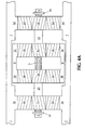
- Fig. 4a is a schematic illustration of the described embodiment of Fig. 1 illustrating an example of gear locations prior to start up or prior to rotating planet gear carrier 4.
- Fig. 4b is a schematic illustration of the described embodiment of Fig. 1 illustrating an example of gear locations after start up when equilibrium load sharing or balanced load amongst gears has been achieved. It will be appreciated that a plurality of planetary gear sets employing the principles of the present invention may be used as dictated by the design criteria for the transmission.
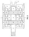
- Fig. 5 is a schematic illustration of an embodiment similar to Fig. 1 wherein there are only two planetary gear sets. The principles of operation of the present invention would be the same.
- sun shaft 5 were the drive shaft and rotational power was inputted to sun shaft 5 by a power source (not illustrated) to rotate sun shaft 5 in the counterclockwise direction, operation would take place as previously described in connection with Fig. 1 wherein planet gear carrier 4 is rotated in the clockwise direction by a power source. If sun shaft 5 is the drive shaft and planet carrier 4 is the driven member, the transmission becomes a speed reducing transmission.
- sun gears 1a and 1b would tend to move apart in the axial direction of sun shaft 5 and cause sun gears 1c and 1d to tend to move apart in the axial direction of the sun shaft 5.
- sun gear 1b and sun gear 1c would tend to move toward one another in the axial direction of the sun shaft 5.
- cylindrical member 10, or some other type of spacer would be placed between sun gear 1b and sun gear 1c.
- ring gears 3a and 3b would tend to move together in the axial direction of the cylindrical transmission housing and ring gears 3c and 3d would tend to move together in the axial direction of the cylindrical transmission housing.
- ring gears 3a and 3b could be a spline mounted unit such as the spline mounted ring gear unit 3b, 8, 3c illustrated in Fig, 1 .
- ring gears 3c and 3d could be such a spline mounted unit.
- each of cylindrical shaped ring gears 3a, 3b, 3c and 3d could be a separate cylindrical member each splined to the interior circumferential surface of cylindrical transmission housing 7 with a spacer member disposed between ring gears 3a and 3b and another spacer member disposed between ring gears 3c and 3d.
- a stop member 24 would be mounted at the end of sun shaft 5 adjacent the first end 21 of cylindrical transmission housing 7 to restrain axial movement of sun gear 1a in the axial direction toward the first end 21 of cylindrical transmission housing 7 and maintain sun gear 1a in engagement with planet gears 2a.
- a stop member 25 would be provided at the second end of sun shaft 5 to restrain axial movement of sun gear 1d toward the second end 22 of cylindrical transmission housing 7.
- the distance of axial movement of sun gears or ring gears in the practice of the present invention would be, for example, about 0.1 mm to 1 mm.
- the present invention provides for a commercially practical, cost-effective planetary gear transmission having multiple planetary gear sets in the gear train by employing helical cut gears.
- the helical cut gears used in the planetary gear transmission of the present invention need only have commercially practical, cost-effective manufacturing tolerances.
Landscapes
- Engineering & Computer Science (AREA)
- General Engineering & Computer Science (AREA)
- Mechanical Engineering (AREA)
- Retarders (AREA)
- Control Of Motors That Do Not Use Commutators (AREA)
- Optical Communication System (AREA)
- Transmission Devices (AREA)
- Transition And Organic Metals Composition Catalysts For Addition Polymerization (AREA)
- Structure Of Transmissions (AREA)
Claims (9)
- Planetengetriebe, welches Folgendes aufweist:ein zylindrisches Getriebegehäuse (7) mit einer längsverlaufenden Mittelachse, einem ersten Ende und einem zweiten Ende;einen Planetenradträger (4), welcher zur Drehung innerhalb des Getriebegehäuses (7) befestigt ist, und welcher Planetenräder (2a, 2b) trägt, die zwischen einem an dem Getriebegehäuse (7) angeordneten Hohlrad (3a) und einem auf der längsverlaufenden Mittelachse des Getriebegehäuses (7) befindlichen Sonnenrad (1a) angeordnet sind, wobei der Planetenradträger (4) einen ersten Satz von drehbar befestigten Planetenrädern (2a) und einen zweiten Satz von drehbar befestigten Planetenrädern (2b), welcher in Längsrichtung von dem ersten Satz von Planetenrädern (2a) in Richtung des zweiten Endes des Getriebegehäuses (7) beabstandet angeordnet ist, aufweist;wobei die Planetenräder des ersten Satzes (2a) jeweils eine Schrägverzahnung mit einer gleichen Richtung und einem gleichen Winkel aufweisen;
wobei die Planetenräder des zweiten Satzes (2b) jeweils eine Schrägverzahnung mit einer gleichen Richtung und einem gleichen Winkel aufweisen, die entgegengesetzt zur Richtung und zum Winkel der Schrägverzahnung der Planetenräder des ersten Satzes (2a) sind;
ein erstes zylindrisch ausgebildetes Hohlrad (3a), das an dem Getriebegehäuse (7) angeordnet ist und das an einer axialen Bewegung in einer Richtung der längsverlaufenden Mittelachse des Getriebegehäuses (7) in Richtung des ersten Endes des Getriebegehäuses (7) gehindert wird, und das an einer umlaufenden Bewegung in einer umlaufenden Richtung des Getriebegehäuses (7) gehindert wird;
wobei das erste zylindrische Hohlrad (3a) eine Schrägverzahnung mit einer Richtung und einem Winkel aufweist, die entgegengesetzt zur Richtung und zum Winkel der Schrägverzahnung der Planetenräder des ersten Satzes (2a) sind;
wobei die Planetenräder des ersten Satzes (2a) zur Drehung mit dem ersten Hohlrad (3a) bei Drehung des Planetenradträgers (4) in Eingriff mit dem ersten Hohlrad (3a) sind;
ein zweites zylindrisch ausgebildetes Hohlrad (3b), das an dem Getriebegehäuse (7) zur axialen Bewegung in Richtung der längsverlaufenden Mittelachse des Getriebegehäuses (7) angeordnet ist und an einer umlaufenden Bewegung in der umlaufenden Richtung des Getriebegehäuses (7) gehindert wird;
wobei das zweite zylindrisch ausgebildete Hohlrad (3b) eine Schrägverzahnung mit einer Richtung und einem Winkel aufweist, die entgegengesetzt zur Richtung und zum Winkel der Schrägverzahnung des Planetengetriebes des zweiten Satzes (2b) sind;
wobei die Planetenräder des zweiten Satzes (2b) zur Drehung in dem zweiten Hohlrad (3b) bei Drehung des Planetenradträgers (4) in Eingriff mit dem zweiten Hohlrad (3b) sind;
eine Sonnenradwelle (9), die zur Drehung innerhalb des Getriebegehäuses (7) befestigt ist, wobei die Sonnenradwelle (5) eine Achse aufweist, die parallel zu der und übereinstimmend mit der längsverlaufenden Mittelachse des Getriebegehäuses (7) ist;
wobei die Sonnenradwelle (9) ein erstes Ende, das benachbart zum ersten Ende des Getriebegehäuses (7) angeordnet ist, und ein zweites Ende, das benachbart zum zweiten Ende des Getriebegehäuses (7) angeordnet ist, aufweist;
ein erstes Sonnenrad (1a), das auf der Sonnenradwelle (5) zur axialen Bewegung auf der Sonnenradwelle (5) befestigt ist, und des Weiteren zur Übertragung der Drehleistung zwischen dem ersten Sonnenrad (1a) und der Sonnenradwelle (5) auf der Sonnenradwelle (5) befestigt ist;
wobei das erste Sonnenrad (1a) eine Schrägverzahnung mit einer Richtung und einem Winkel aufweist, die entgegengesetzt zur Richtung und zum Winkel der Schrägverzahnung der Planetenräder des ersten Satzes (2a) sind;
wobei das erste Sonnenrad (1a) zur Übertragung der Drehleistung zwischen dem ersten Sonnenrad (1b) und den Planetenrädern des ersten Satzes (2a) in Eingriff mit den Planetenrädern des ersten Satzes (2a) ist;
ein zweites Sonnenrad (1b), das auf der Sonnenradwelle (5) zur axialen Bewegung auf der Sonnenradwelle (5) befestigt ist, und des Weiteren zur Übertragung der Drehleistung zwischen dem zweiten Sonnenrad (1b) und der Sonnenradwelle (5) auf der Sonnenradwelle (5) befestigt ist;
wobei das zweite Sonnenrad (1b) eine Schrägverzahnung mit einer Richtung und einem Winkel aufweist, die entgegengesetzt zur Richtung und zum Winkel der Schrägverzahnung der Planetenräder des zweiten Satzes (2b) sind;
wobei das zweite Sonnenrad (1b) zur Übertragung der Drehleistung zwischen dem zweiten Sonnenrad und den Planetenrädern des zweiten Satzes (2b) in Eingriff mit den Planetenrädern des zweiten Satzes (2b) ist;
ein erstes Sonnenradbauteil (1c), das zwischen dem ersten Sonnenrad (1a) und dem zweiten Sonnenrad (1b) angeordnet ist, um Kraft in Richtung der Sonnenradwellenachse zwischen dem ersten Sonnenrad (1a) und dem zweiten Sonnenrad (1b) zu übertragen;
wobei die entsprechenden Schrägverzahnungen auf dem ersten Sonnenrad (1a) und dem zweiten Sonnenrad (1b) Richtungen und Winkel aufweisen, wodurch die Drehung des ersten Sonnenrades (1a) und des zweiten Sonnenrades (1b), die entsprechend mit den Planetenrädern des ersten Satzes (2a) bzw. den Planetenrädern des zweiten Satzes (2b) in Eingriff sind, Kräfte erzeugt, die das erste Sonnenrad (1a) und das zweite Sonnenrad (1b) in der axialen Richtung der Sonnenradwelle (5) aufeinanderzu zwingen;
dadurch gekennzeichnet, dass
der Planetenradträger (4) einen dritten Satz von drehbar befestigten Planetenrädern (2c) trägt, die in Längsrichtung von dem zweiten Satz von Planetenrädern (2b) in Richtung des zweiten Endes des Getriebegehäuses (7) beabstandet angeordnet sind;
wobei die Planetenräder des dritten Satzes (2c) jeweils eine Schrägverzahnung mit einer gleichen Richtung und einem gleichen Winkel aufweisen, die entgegengesetzt zur Richtung und zum Winkel der Schrägverzahnung der Planetenträder des zweiten Satzes (2b) sind;
ein drittes zylindrisch ausgebildetes Hohlrad (3c), das auf dem Getriebegehäuse (7) angeordnet ist, und zur axialen Bewegung in Richtung der längsverlaufenden Mittelachse des Getriebegehäuses (7) an dem Getriebegehäuse (7) befestigt ist, und welches an der umlaufenden Bewegung in umlaufender Richtung des Getriebegehäuses (7) gehindert wird;
wobei das dritte zylindrisch ausgebildete Hohlrad (3c) eine Schrägverzahnung mit einer Richtung und einem Winkel aufweist, die entgegengesetzt zur Richtung und zum Winkel der Schrägverzahnung der Planetenräder des dritten Satzes (2c) sind;
wobei die Planetenräder des dritten Satzes (2c) zur Drehung in dem dritten Hohlrad (3c) bei Drehung des Planetenradträgers (4) in Eingriff mit den Planetenrädern des dritten Satzes (2c) sind;
ein Hohlradbauteil (8), welches zwischen dem zweiten zylindrisch ausgebildeten Hohlrad (3b) und dem dritten zylindrisch ausgebildeten Hohlrad (3c) zur Übertragung von Kraft in Richtung der längsverlaufenden Mittelachse des Getriebegehäuses (7) zwischen dem zweiten zylindrisch angeordneten Hohlrad (3b) und dem dritten zylindrisch angeordneten Hohlrad (3c) angeordnet ist;
ein drittes Sonnenrad (1c), das auf der Sonnenradwelle (5) angeordnet ist und an der axialen Bewegung auf der Sonnenradwelle (5) in Richtung des zweiten Endes der Sonnenradwelle (5) gehindert wird, und das des Weiteren zur Übertragung der Drehleistung zwischen dem dritten Sonnenrad (1c) und der Sonnenradwelle (5) auf der Sonnenradwelle (5) befestigt ist;
wobei das dritte Sonnenrad (1c) eine Schrägverzahnung mit einer Richtung und einem Winkel aufweist, die entgegengesetzt zur Richtung und zum Winkel der Schrägverzahnung auf den Planetenrädern des dritten Satzes (2c) sind;
wobei das dritte Sonnenrad (1c) zur Übertragung der Drehleistung zwischen dem dritten Sonnenrad (1c) und den Planetenrädern des dritten Satzes (2c) in Eingriff mit den Planetenrädern des dritten Satzes (2c) ist. - Planetengetriebe nach Anspruch 1, welches des Weiteren Folgendes aufweist:das dritte Sonnenrad (1c), welches zur axialen Bewegung auf der Sonnenradwelle (5) auf der Sonnenradwelle (5) befestigt ist, und welches des Weiteren zur Übertragung der Drehleistung zwischen dem dritten Sonnenrad (1c) und der Sonnenradwelle (5) auf der Sonnenradwelle (5) befestigt ist;wobei der Sonnenradträger (4) einen vierten Satz von drehbar befestigten Planetenrädern (2d) trägt, die in Längsrichtung von dem dritten Satz von Planetenrädern (2c) in Richtung des zweiten Endes des Getriebegehäuses (7) beabstandet angeordnet sind;
wobei die Planetenräder des vierten Satzes (2d) jeweils eine Schrägverzahnung mit einer gleichen Richtung und einem gleichen Winkel aufweisen, die entgegengesetzt zur Richtung und zum Winkel der Schrägverzahnung der Planetenräder des dritten Satzes (2c) sind;
ein viertes zylindrisch ausgebildetes Hohlrad (3d), das in dem Getriebegehäuse (7) angeordnet ist und an der axialen Bewegung in Richtung der längsverlaufenden Mittelachse des Getriebegehäuses in Richtung des zweiten Endes des Getriebegehäuses (7) gehindert wird, und das an der umlaufenden Bewegung in der umlaufenden Richtung des Getriebegehäuses (7) gehindert wird;
wobei das vierte zylindrisch ausgebildete Hohlrad (3d) eine Schrägverzahnung mit einer Richtung und einem Winkel aufweist, die entgegengesetzt zur Richtung und zum Winkel der Schrägverzahnung der Planetenräder des vierten Satzes (2d) sind;
wobei die Planetenräder des vierten Satzes (2d) zur Drehung in dem vierten Hohlrad (3d) bei Drehung des Planetenradträgers (4) in Eingriff mit dem vierten Hohlrad (3d) sind;
ein viertes Sonnenrad (1d), welches zur axialen Bewegung auf der Sonnenradwelle (5) auf der Sonnenradwelle (5) befestigt ist, und welches des Weiteren zur Übertragung der Drehleistung zwischen dem vierten Sonnenrad (1d) und der Sonnenradwelle (5) auf der Sonnenradwelle (5) befestigt ist;
wobei das vierte Sonnenrad (1d) eine Schrägverzahnung mit einer Richtung und einem Winkel aufweist, die entgegengesetzt zur Richtung und zum Winkel der Schrägverzahnung auf den Planetenrädern des vierten Satzes (2d) sind;
wobei das vierte Sonnenrad (1d) zur Übertragung der Drehleistung zwischen dem vierten Sonnenrad (1d) und den Planetenrädern des vierten Satzes (2d) in Eingriff mit den Planetenrädern des vierten Satzes (2d) ist;
ein Bauteil (10), das zwischen dem dritten Sonnenrad (1c) und dem vierten Sonnenrad (1d) zur Übertragung von Kraft in Richtung der Sonnenwellenachse zwischen dem dritten Sonnenrad (1c) und dem vierten Sonnenrad (1d) angeordnet ist;
wobei die entsprechenden Schrägverzahnungen auf dem dritten Sonnenrad (1c) und dem vierten Sonnenrad (1d) Richtungen und Winkel aufweisen, wobei die Drehung des dritten Sonnenrads (1c) und des vierten Sonnenrads (1d), die entsprechend mit den Planetenrädern des dritten Satzes (2c) bzw. den Planetenrädern des vierten Satzes (2d) in Eingriff sind, Kräfte erzeugt, die das dritte Sonnenrad (1c) und das vierte Sonnenrad (1d) in der axialen Richtung der Sonnenradwelle (5) aufeinander zwingen;
wobei die entsprechenden Schrägverzahnungen auf dem zweiten zylindrisch ausgebildeten Hohlrad (3b) und dem dritten zylindrisch ausgebildeten Hohlrad (3c) Richtungen und Winkel aufweisen, wobei die Drehung von Planetenrädern des zweiten Satzes (2b) und Planetenrädern des dritten Satzes (2c), die entsprechend mit dem zweiten zylindrisch ausgebildete Hohlrad (3b) bzw. dem dritten zylindrisch ausgebildeten Hohlrad (3c) in Eingriff miteinander bringt, Kräfte erzeugt, die das zweite zylindrisch ausgebildete Hohlrad (3b) und das dritte zylindrisch ausgebildete Hohlrad (3c) in Richtung der längsverlaufenden Mittelachse des Getriebegehäuses (7) aufeinanderzu zwingen. - Planetengetriebe nach Anspruch 1, welches des Weiteren Folgendes aufweist:den Planetenradträger (4), welcher eine Vielzahl von Sätzen von drehbar befestigten Planetenrädern (2a-d) mit Schrägverzahnung aufweist;eine Vielzahl von zylindrisch ausgebildeten Hohlrädern (3a-d) mit Schrägverzahnung, die in dem Getriebegehäuse (7) angeordnet sind;wobei die Vielzahl von Sätzen von Planetenrädern (2a-d) mit Schrägverzahnung in Eingriff mit entsprechenden zylindrisch ausgebildeten Hohlrädern (3a-3d) zur Drehung darin bei Drehung des Planetenradträgers (4) ist;
eine Vielzahl von Sonnenrädern (1a-d) mit Schrägverzahnung, die auf der Sonnenradwelle (5) zur Übertragung der Drehleistung zwischen den Sonnenrädern (1a-d) und der Sonnenradwelle (5) befestigt sind, die mit entsprechenden Sätzen von Planetenrädern (2a-d) mit Schrägverzahnung in Eingriff sind, um die Drehleistung zwischen entsprechenden Sonnenrändern mit Schrägverzahnung (1a-d) und entsprechenden Sätzen von Planetenrädern (2a-d) mit Schrägverzahnung zu übertragen. - Planetengetriebe, welches Folgendes aufweist:ein zylindrisches Getriebegehäuse (7) mit einer längsverlaufenden Mittelachse, einem ersten Ende und einem zweiten Ende;einen Planetenradträger (4), welcher zur Drehung innerhalb des Getriebegehäuses (7) befestigt ist, und welcher Planetenräder (2a, 2b) trägt, die zwischen einem an dem Getriebegehäuse (7) angeordneten Hohlrad (3a) und einem auf der längsverlaufenden Mittelachse des Getriebegehäuses (7) befindlichen Sonnenrad (1a) angeordnet sind, wobei der Planetenradträger (4) Planetenräder (2a, 2b) trägt, die zwischen einem an dem Getriebegehäuse (7) angeordneten Hohlrad (3a) und einem auf der längsverlaufenden Mittelachse des Getriebegehäuses (7) vorhandenen Sonnenrad (1a) angeordnet sind, wobei der Planetenradträger (4) einen ersten Satz von drehbar befestigten Planetenrädern (2a) und einen zweiten Satz von drehbar befestigten Planetenrädern (2b), die in Längsrichting von dem ersten Satz von Planetenrädern (2a) in Richtung des zweiten Endes des Getriebegehäuses (7) beabstandet angeordnet ist, aufweist;wobei die Planetenräder des ersten Satzes (2a) jeweils eine Schrägverzahnung mit einer gleichen Richtung und einem gleichen Winkel aufweisen;
wobei die Planetenräder des zweiten Satzes (2b) jeweils eine Schrägverzahnung mit einer gleichen Richtung und einem gleichen Winkel aufweisen, die entgegengesetzt zur Richtung und zum Winkel der Schrägverzahnung der Planetenräder des ersten Satzes (2a) sind;
ein erstes zylindrisch ausgebildetes Hohlrad (3a), das in dem Getriebegehäuse (7) angeordnet ist und zur Bewegung in eine Richtung der längsverlaufenden Mittelachse des Getriebegehäuses (7) befestigt ist, und an der umlaufenden Bewegung in einer umlaufenden Richtung des Getriebegehäuses (7) gehindert wird;
wobei das erste zylindrisch ausgebildete Hohlrad (3a) eine Schrägverzahnung mit einer Richtung und einem Winkel aufweist, die entgegengesetzt zur Richtung und zum Winkel der Schrägverzahnung der Planetenräder des ersten Satzes (2a) sind;
wobei die Planetenräder des ersten Satzes (2a) bei Drehung des Planetenradträgers (4) zur Drehung in dem ersten Hohlrad (3a) mit dem ersten Hohlrad (3a) in Eingriff sind;
ein zweites zylindrisch ausgebildetes Hohlrad (3b), das in dem Getriebegehäuse (7) angeordnet ist und zur Bewegung in Richtung der längsverlaufenden Mittelachse des Getriebegehäuses (7) befestigt ist, und an der umlaufenden Bewegung in der umlaufenden Richtung des Getriebegehäuses (7) gehindert wird;
wobei das zweite zylindrisch ausgebildete Hohlrad (3b) eine Schrägverzahnung mit einer Richtung und einem Winkel aufweist, die entgegengesetzt zur Richtung und zum Winkel der Schrägverzahnung der Planetenräder des zweiten Satzes (2b) sind;
wobei die Planetenräder des zweiten Satzes (2b) zur Drehung in dem zweiten Hohlrad (3b) bei Drehung des Planetenradträgers (4) in Eingriff mit dem zweiten Hohlrad (3b) sind;
ein Bauteil, das zwischen dem ersten zylindrisch ausgebildeten Hohlrad (3a) und dem zweiten zylindrisch ausgebildeten Hohlrad (3b) zur Übertragung der Kraft in Richtung der längsverlaufenden Mittelachse des Getriebegehäuses (7) zwischen dem ersten zylindrischen Hohlrad (3a) und dem zweiten zylindrisch ausgebildeten Hohlrad (3b) angeordnet ist;
eine Sonnenradwelle (5), die zur Drehung innerhalb des Getriebegehäuses (7) befestigt ist, wobei die Sonnenradwelle (5) eine Achse aufweist, die parallel zu der und übereinstimmend mit der längsverlaufenden Mittelachse des Getriebegehäuses (7) ist;
wobei die Sonnenradwelle (5) ein erstes Ende, das benachbart zum ersten Ende des Getriebegehäuses (7) ist, und ein zweites Ende, das benachbart zum zweiten Ende des Getriebegehäuses (7) ist, aufweist;
ein erstes Sonnenrad (1a), das auf der Sonnenradwelle (5) befestigt ist und an der axialen Bewegung auf der Sonnenradwelle (5) in Richtung des ersten Endes der Sonnenradwelle (7) gehindert wird und des Weiteren zur Übertragung der Drehleistung zwischen dem ersten Sonnenrad (1a) und der Sonnenradwelle (5) befestigt ist;
wobei das erste Sonnenrad (1a) eine Schrägverzahnung mit einer Richtung und einem Winkel aufweist, die entgegengesetzt zur Richtung und zum Winkel der Schrägverzahnung der Planetenräder des ersten Satzes (2a) sind;
wobei das erste Sonnenrad (1a) zur Übertragung der Drehleistung zwischen dem ersten Sonnenrad (1a) und den Planetenrädern des ersten Satzes (2a) in Eingriff mit den Planetenrädern des ersten Satzes (2a) ist;
ein zweites Sonnenrad (1b), das zur axialen Bewegung auf der Sonnenradwelle (5) in Richtung des zweiten Endes der Sonnenradwelle (5) auf der Sonnenradwelle (5) befestigt ist, und des Weiteren zur Übertragung der Drehleistung zwischen dem zweiten Sonnenrad (1b) und der Sonnenradwelle (5) auf der Sonnenradwelle (5) befestigt ist;
wobei das zweite Sonnenrad (1b) eine Schrägverzahnung mit einer Richtung und einem Winkel aufweist, die entgegengesetzt zur Richtung und zum Winkel der Schrägverzahnung der Planetenräder des zweiten Satzes (3b) sind;
wobei das zweite Sonnenrad (1b) zur Übertragung der Drehleistung zwischen dem zweiten Sonnenrad (1b) und den Planetenrädern des zweiten Satzes (2b) in Eingriff mit den Planetenrädern des zweiten Satzes (2b) ist;
wobei die entsprechenden Schrägverzahnungen auf dem ersten zylindrisch ausgebildeten Hohlrad (3a) und dem zweiten zylindrisch ausgebildeten Hohlrad (3b) Richtungen und Winkel aufweisen, wobei die Drehung der Planetenräder des ersten Satzes (2a) und die Planetenräder des zweiten Satzes (2b), die entsprechend mit dem ersten zylindrisch ausgebildeten Hohlrad (3a) bzw. mit dem zweiten zylindrisch ausgebildeten Hohlrad (3b) in Eingriff sind, Kräfte erzeugen, die das erste zylindrisch ausgebildete Hohlrad (3a) und das zweite zylindrisch ausgebildete Hohlrad (3b) in der Richtung der längsverlaufenden Mittelachse des Getriebegehäuses (7) aufeinanderzu zwingen;
dadurch gekennzeichnet, dass
der Planetenradträger (4) einen dritten Satz von drehbar befestigten Planetenrädern (2c) trägt, die in Längsrichtung von dem zweiten Satz von Planetenrädern (2b) in Richtung des zweiten Endes des Getriebegehäuse (7) beabstandet angeordnet sind;
wobei die Planetenräder des dritten Satzes (2c) jeweils eine Schrägverzahnung mit einer gleichen Richtung und einem gleichen Winkel aufweisen, die entgegengesetzt zur Richtung und zum Winkel der Schrägverzahnung der Planetenräder des zweiten Satzes (2b) sind;
ein drittes zylindrisch ausgebildetes Hohlrad (3c), das in dem Getriebegehäuse (7) angeordnet ist und an der Bewegung in Richtung der längsverlaufenden Mittelachse des Getriebegehäuses (7) in Richtung des zweiten Endes des Getriebegehäuses (7) gehindert wird, und das an der umlaufenden Bewegung in der umlaufenden Richtung des Getriebegehäuses (7) gehindert wird, wobei das dritte zylindrisch ausgebildete Hohlrad (3c) eine Schrägverzahnung mit einer Richtung und einem Winkel aufweist, die entgegengesetzt zur Richtung und zum Winkel der Schrägverzahnung der Planetenräder des dritten Satzes (2c) sind;
wobei die Planetenräder des dritten Satzes (2c) zur Drehung in dem dritten Hohlrad (3c) bei Drehung des Planetenradträgers (4) mit dem dritten Hohlrad (3c) in Eingriff sind;
ein drittes Sonnenrad (1c), das zur axialen Bewegung auf der Sonnenradwelle befestigt ist, und das des Weiteren zur Übertragung der Drehleistung zwischen dem dritten Sonnenrad (1c) und der Sonnenradwelle (5) auf der Sonnenradwelle (5) befestigt ist;
wobei das dritte Sonnenrad (1c) eine Schrägverzahnung mit einer Richtung und einem Winkel aufweist, die entgegengesetzt zur Richtung und zum Winkel der Schrägverzahnung auf den Planetenrädern des dritten Satzes (2c) sind;
wobei das dritte Sonnenrad (1c) zur Übertragung von Drehleistung zwischen dem dritten Sonnenrad (1c) und den Planetenrädern des dritten Satzes (2c) im Eingriff mit Planetenrädern des dritten Satzes (2c) ist;
wobei das zweite Sonnenrad (1b) zur axialen Bewegung auf der Sonnenradwelle (5) auf der Sonnenradwelle (5) angeordnet ist;
ein Bauteil, das zur Übertragung von Kraft in Richtung der dritten Sonnenradwellenachse zwischen dem zweiten Sonnenrad (1b) und dem dritten Sonnenrad (1c) zwischen dem zweiten Sonnenrad (1b) und dem dritten Sonnenrad (1c) angeordnet ist. - Planetengetriebe nach Anspruch 4, welches des Weiteren Folgendes aufweist:den Planetenradträger (4), der eine Vielzahl von Sätzen von drehbar befestigten Planetenrädern (2a-d) mit Schrägverzahnung aufweist;eine Vielzahl von zylindrisch ausgebildeten Hohlrädern (3a-d) mit Schrägverzahnung, die in dem Getriebegehäuse (7) angeordnet sind;wobei die Vielzahl von Sätzen von Planetenrädern (2a-d) mit Schrägverzahnung bei Drehung des Planetenradträgers (4) mit entsprechenden zylindrisch ausgebildeten Hohlrädern (3a-d) mit Schrägverzahnung zur Drehung darin in Eingriff sind;
eine Vielzahl von Sonnenrädern (1a-d) mit Schrägverzahnung auf der Sonnenradwelle (5) zur Übertragung der Drehleistung zwischen den Sonnenrädern (1a-d) und der Sonnenradwelle (5) befestigt sind, und wobei die Sonnenräder (1a-d) in Eingriff mit entsprechenden Sätzen von Planetenrädern (2a-d) mit Schrägverzahnung zur Übertragung von Drehleistung zwischen entsprechenden Sonnenrädern (1a-d) mit Schrägverzahnung und entsprechenden Sätzen von Planetenrädern (2a-d) mit Schrägverzahnung sind. - Verfahren zur Übertragung von Drehleistung mit einem Planetengetriebe, welches Folgendes umfasst:Bereitstellen eines zylindrischen Getriebegehäuses (7) mit einer längsverlaufenden axialen Richtung;Bereitstellen einer Vielzahl von Planetenradsätzen (2a, 2b) in dem zylindrischen Getriebegehäuse (7), wobei jeder Planetenradsatz (2a, 2b) eine Vielzahl von Planetenrädern mit Schrägverzahnung, die in einem Planetenradträger (4) angeordnet sind, aufweist, und eines in dem Getriebegehäuse (7) angeordneten Hohlrades (3a, 3b) mit Schrägverzahnung, gekennzeichnet durch die Bereitstellung von mindestens drei Planetenradsätzen (2a-c), die zusätzlich ein Sonnenrad (1a-c) aufweisen, das auf einer Sonnenradwelle (5) angeordnet ist, die parallel zu der längsverlaufenden axialen Richtung des zylindrischen Getriebegehäuses (7) befestigt ist;Veranlassen, dass jedes Planetenrad mit Schrägverzahnung von jedem Planetenradsatz (2a-c) mit seinem entsprechenden Hohlrad (3a-c) mit Schrägverzahnung und mit seinem entsprechenden Sonnenrad (1a-c) mit Schrägverzahnung in Eingriff kommt;Befestigen des Sonnenrads (1a-c) mit Schrägverzahnung von mindestens einem Planetenradsatz (2a-c) auf der Sonnenradwelle (5) zur Bewegung in der längsverlaufenden axialen Richtung auf der Sonnenradwelle und Befestigen des Hohlrads (3a-c) mit Schrägverzahnung von mindestens einem Planetenradsatz (2a-c) in dem Getriebegehäuse (7) zur Bewegung in der längsverlaufenden axialen Richtung in dem Getriebegehäuse (7);Anwenden eines Drehmoments auf das Planetengetriebe, was zu einer Bewegung in der längsverlaufenden axialen Richtung jedes Sonnenrads (1a-c) mit Schrägverzahnung, das zur längsverlaufenden axialen Richtungsbewegung befestigt ist, und jedes Hohlrads mit Schrägverzahnung, das zur Bewegung in der längsverlaufenden axialen Richtung befestigt ist, führt, was dadurch eine gleichmäßige Belastungsverteilung auf alle Planetenradsätze von jedem der mindestens drei Planetenradsätze (2a-c) mit sich bringt.
- Verfahren zum Übertragen von Drehleistung mit einem Planetengetriebe gemäß Anspruch 6, welches des Weiteren die Bereitstellung von mehr als drei der Planetenradsätze (2a-c) aufweist.
- Verfahren zur Übertragung von Drehleistung mit einem Planetengetriebe gemäß Anspruch 6, wobei das Anwenden des Drehmoments bei mindestens einem der Planetenradsätze (2a-c) dazu führt, dass sich das Sonnenrad (1a-c) mit Schrägverzahnung und das Hohlrad (3a-c) mit Schrägverzahnung von dem einen Planetenradsatz (2a-c) in entgegengesetzte längsverlaufende axiale Richtungen bewegen.
- Verfahren zur Übertragung von Drehleistung mit einem Planetengetriebe gemäß Anspruch 7, wobei das Anwenden des Drehmoments bei mehr als einem von den Planetenradsätzen (2a-c) dazu führt, dass sich das Sonnenrad (1a-c) mit Schrägverzahnung und das Hohlrad (3a-c) mit Schrägverzahnung von jedem entsprechenden Planetenradsatz (2a-2c) von den mehr als einem der Planetenradsätze in entgegengesetzte längslaufende axiale Richtungen bewegen.
Applications Claiming Priority (1)
| Application Number | Priority Date | Filing Date | Title |
|---|---|---|---|
| PCT/US2000/018792 WO2001031231A1 (en) | 1999-07-16 | 2000-08-10 | Gearing for power sharing in planetary transmission |
Publications (3)
| Publication Number | Publication Date |
|---|---|
| EP1210532A1 EP1210532A1 (de) | 2002-06-05 |
| EP1210532A4 EP1210532A4 (de) | 2006-03-22 |
| EP1210532B1 true EP1210532B1 (de) | 2008-10-29 |
Family
ID=21741575
Family Applications (1)
| Application Number | Title | Priority Date | Filing Date |
|---|---|---|---|
| EP00968311A Expired - Lifetime EP1210532B1 (de) | 2000-08-10 | 2000-08-10 | Planetengetriebe mit lastausgleich |
Country Status (10)
| Country | Link |
|---|---|
| EP (1) | EP1210532B1 (de) |
| JP (1) | JP4782341B2 (de) |
| CN (1) | CN1304770C (de) |
| AT (1) | ATE412839T1 (de) |
| AU (1) | AU2000278247A1 (de) |
| CA (1) | CA2379240C (de) |
| DE (1) | DE60040673D1 (de) |
| DK (1) | DK1210532T3 (de) |
| ES (1) | ES2315242T3 (de) |
| MX (1) | MXPA02000604A (de) |
Cited By (1)
| Publication number | Priority date | Publication date | Assignee | Title |
|---|---|---|---|---|
| EP3663609B1 (de) | 2017-10-13 | 2023-08-30 | Aisin Corporation | Antriebsvorrichtung für fahrzeug |
Families Citing this family (13)
| Publication number | Priority date | Publication date | Assignee | Title |
|---|---|---|---|---|
| DE102009052898B4 (de) * | 2009-11-13 | 2011-12-29 | Saia-Burgess Dresden Gmbh | Mehrstufiges Planetengetriebe |
| CN102588550B (zh) * | 2012-03-16 | 2014-11-05 | 李上柱 | 齿轮传动机构 |
| SE1550263A1 (en) * | 2015-03-04 | 2016-09-05 | Swepart Trans Ab | Gear train |
| US10253848B2 (en) * | 2015-10-30 | 2019-04-09 | Faraday & Future Inc. | Thrust balanced planetary gear assemblies |
| PL233394B1 (pl) * | 2015-11-18 | 2019-10-31 | Efneo Spolka Z Ograniczona Odpowiedzialnoscia | Mechanizm wolnobiegu |
| CN107345557A (zh) * | 2016-05-07 | 2017-11-14 | 熵零技术逻辑工程院集团股份有限公司 | 一种变速传动机构 |
| FR3058771B1 (fr) * | 2016-11-14 | 2020-02-28 | Safran Electronics & Defense | Dispositif de transmission mecanique |
| US10207580B2 (en) * | 2016-12-09 | 2019-02-19 | Deere & Company | Work vehicle drive with compact multi-speed shift assembly |
| CN107685828B (zh) * | 2017-09-19 | 2023-03-24 | 八方电气(苏州)股份有限公司 | 电动自行车无级变速传动装置 |
| CN109027140B (zh) * | 2018-09-30 | 2023-12-19 | 杭州星河传动机械研究院有限公司 | 一种滚套行星减速机 |
| KR102235913B1 (ko) * | 2019-10-20 | 2021-04-05 | 한국생산기술연구원 | 헬리컬 유성 감속부를 갖는 선박용 터닝기어와, 그 설계방법 및, 이 설계방법을 구현하는 컴퓨터 프로그램을 기록하고 컴퓨터로 읽을 수 있는 기록 매체 |
| CN110792735B (zh) * | 2019-12-09 | 2023-12-19 | 郑机所(郑州)传动科技有限公司 | 一种提高多级行星减速器稳定性的方法和一种行星减速器 |
| CN112957141B (zh) * | 2021-01-27 | 2022-06-03 | 四川大学华西第二医院 | 一种妇产科专用消毒装置 |
Family Cites Families (10)
| Publication number | Priority date | Publication date | Assignee | Title |
|---|---|---|---|---|
| US1425430A (en) * | 1918-05-06 | 1922-08-08 | Skayef Ball Bearing Company | Planetary gear |
| DE1157049B (de) * | 1958-02-15 | 1963-11-07 | E H Wilhelm G Stoeckicht Dr In | Umlaufraedergetriebe mit doppelschraegverzahnten Umlaufraedern |
| CH411499A (de) * | 1961-04-26 | 1966-04-15 | Ceskoslovenske Z Naftovych Mot | Zweireihiges Planetenwechselgetriebe |
| GB1163024A (en) * | 1966-11-16 | 1969-09-04 | Associatd Electrical Ind Ltd | Improvements relating to Helical Epicyclic Gearing |
| JPS4840262B1 (de) * | 1968-03-15 | 1973-11-29 | ||
| DE3005463A1 (de) * | 1980-02-14 | 1981-08-20 | Thyssen Industrie Ag, 4300 Essen | Planetengetriebe |
| DE4216400A1 (de) * | 1992-05-18 | 1993-11-25 | Zahnradfabrik Friedrichshafen | Planetengetriebe in doppelt schrägverzahnter Bauweise |
| DE4216399A1 (de) * | 1992-05-18 | 1993-11-25 | Zahnradfabrik Friedrichshafen | Planetengetriebe |
| US5472383A (en) * | 1993-12-27 | 1995-12-05 | United Technologies Corporation | Lubrication system for a planetary gear train |
| FR2760059B1 (fr) * | 1997-02-21 | 1999-04-30 | Somfy | Reducteur planetaire a dentures obliques opposees |
-
2000
- 2000-08-10 JP JP2001533343A patent/JP4782341B2/ja not_active Expired - Fee Related
- 2000-08-10 ES ES00968311T patent/ES2315242T3/es not_active Expired - Lifetime
- 2000-08-10 CA CA002379240A patent/CA2379240C/en not_active Expired - Fee Related
- 2000-08-10 DK DK00968311T patent/DK1210532T3/da active
- 2000-08-10 AU AU2000278247A patent/AU2000278247A1/en not_active Abandoned
- 2000-08-10 AT AT00968311T patent/ATE412839T1/de not_active IP Right Cessation
- 2000-08-10 CN CNB008169438A patent/CN1304770C/zh not_active Expired - Fee Related
- 2000-08-10 EP EP00968311A patent/EP1210532B1/de not_active Expired - Lifetime
- 2000-08-10 DE DE60040673T patent/DE60040673D1/de not_active Expired - Lifetime
- 2000-08-10 MX MXPA02000604A patent/MXPA02000604A/es active IP Right Grant
Cited By (1)
| Publication number | Priority date | Publication date | Assignee | Title |
|---|---|---|---|---|
| EP3663609B1 (de) | 2017-10-13 | 2023-08-30 | Aisin Corporation | Antriebsvorrichtung für fahrzeug |
Also Published As
| Publication number | Publication date |
|---|---|
| DK1210532T3 (da) | 2009-03-09 |
| ATE412839T1 (de) | 2008-11-15 |
| DE60040673D1 (de) | 2008-12-11 |
| CA2379240A1 (en) | 2001-05-03 |
| CN1409805A (zh) | 2003-04-09 |
| EP1210532A4 (de) | 2006-03-22 |
| CN1304770C (zh) | 2007-03-14 |
| AU2000278247A1 (en) | 2001-05-08 |
| JP4782341B2 (ja) | 2011-09-28 |
| MXPA02000604A (es) | 2009-01-23 |
| JP2003528263A (ja) | 2003-09-24 |
| EP1210532A1 (de) | 2002-06-05 |
| ES2315242T3 (es) | 2009-04-01 |
| CA2379240C (en) | 2009-04-14 |
Similar Documents
| Publication | Publication Date | Title |
|---|---|---|
| EP1998080B1 (de) | Enduntersetzungsgetriebevorrichtung | |
| EP1210532B1 (de) | Planetengetriebe mit lastausgleich | |
| US6814684B2 (en) | Planetary gear | |
| US6406399B1 (en) | Planetary traction drive transmission | |
| US5324240A (en) | Eccentric gear system | |
| EP0474897B1 (de) | Planetenübersetzungsgetriebe | |
| EP1198679B1 (de) | Getriebe mit inneneingreifenden planetenräder | |
| EP1186798B1 (de) | Stufenloses Toroidgetriebe mit zwei Kammern mit einziger Ausgangscheibe | |
| US3839922A (en) | Transmission gear | |
| US10807467B2 (en) | Epicyclic gearbox | |
| US6179743B1 (en) | Gearing for power sharing in planetary transmission | |
| US11852224B2 (en) | Gear unit for an electric drive system of a motor vehicle and electric drive system with such a gear unit | |
| EP0447866B1 (de) | Planetenreibrollengetriebe | |
| US4770062A (en) | Planetary gear apparatus | |
| US6338691B1 (en) | Gearing for power sharing in planetary transmission | |
| KR930001577B1 (ko) | 기어 | |
| US6929578B1 (en) | Planetary gear carrier assembly | |
| EP4141287A1 (de) | Getriebemechanismus | |
| US4537094A (en) | Gear transmission | |
| KR20220077377A (ko) | 유성기어 감속기와 유성기어 차동장치를 포함한 일체형 캐리어의 구조 | |
| EP0114561A1 (de) | Bewegungsübertragendes System | |
| JP2003048441A (ja) | 車両用四輪駆動装置 | |
| JP4120391B2 (ja) | トロイダル型無段変速機及び無段変速装置 | |
| JPS6174952A (ja) | 多段式変速機 | |
| JP2004218769A (ja) | トロイダル型無段変速機及び無段変速装置 |
Legal Events
| Date | Code | Title | Description |
|---|---|---|---|
| PUAI | Public reference made under article 153(3) epc to a published international application that has entered the european phase |
Free format text: ORIGINAL CODE: 0009012 |
|
| 17P | Request for examination filed |
Effective date: 20020116 |
|
| AK | Designated contracting states |
Kind code of ref document: A1 Designated state(s): AT BE CH CY DE DK ES FI FR GB GR IE IT LI LU MC NL PT SE |
|
| AX | Request for extension of the european patent |
Free format text: AL;LT;LV;MK;RO;SI |
|
| A4 | Supplementary search report drawn up and despatched |
Effective date: 20060207 |
|
| 17Q | First examination report despatched |
Effective date: 20060707 |
|
| 17Q | First examination report despatched |
Effective date: 20060707 |
|
| GRAP | Despatch of communication of intention to grant a patent |
Free format text: ORIGINAL CODE: EPIDOSNIGR1 |
|
| GRAS | Grant fee paid |
Free format text: ORIGINAL CODE: EPIDOSNIGR3 |
|
| GRAA | (expected) grant |
Free format text: ORIGINAL CODE: 0009210 |
|
| AK | Designated contracting states |
Kind code of ref document: B1 Designated state(s): AT BE CH CY DE DK ES FI FR GB GR IE IT LI LU MC NL PT SE |
|
| REG | Reference to a national code |
Ref country code: GB Ref legal event code: FG4D |
|
| REG | Reference to a national code |
Ref country code: CH Ref legal event code: EP |
|
| REG | Reference to a national code |
Ref country code: CH Ref legal event code: PCOW Free format text: HARRIER TECHNOLOGIES, INC.;280 RAILROAD AVENUE;GREENWICH, CT (US) Ref country code: CH Ref legal event code: NV Representative=s name: KIRKER & CIE S.A. |
|
| REG | Reference to a national code |
Ref country code: IE Ref legal event code: FG4D |
|
| REF | Corresponds to: |
Ref document number: 60040673 Country of ref document: DE Date of ref document: 20081211 Kind code of ref document: P |
|
| RAP2 | Party data changed (patent owner data changed or rights of a patent transferred) |
Owner name: HARRIER TECHNOLOGIES, INC. |
|
| REG | Reference to a national code |
Ref country code: DK Ref legal event code: T3 |
|
| NLT2 | Nl: modifications (of names), taken from the european patent patent bulletin |
Owner name: HARRIER TECHNOLOGIES, INC. Effective date: 20090121 |
|
| NLV1 | Nl: lapsed or annulled due to failure to fulfill the requirements of art. 29p and 29m of the patents act | ||
| REG | Reference to a national code |
Ref country code: ES Ref legal event code: FG2A Ref document number: 2315242 Country of ref document: ES Kind code of ref document: T3 |
|
| PG25 | Lapsed in a contracting state [announced via postgrant information from national office to epo] |
Ref country code: AT Free format text: LAPSE BECAUSE OF FAILURE TO SUBMIT A TRANSLATION OF THE DESCRIPTION OR TO PAY THE FEE WITHIN THE PRESCRIBED TIME-LIMIT Effective date: 20081029 |
|
| PG25 | Lapsed in a contracting state [announced via postgrant information from national office to epo] |
Ref country code: NL Free format text: LAPSE BECAUSE OF FAILURE TO SUBMIT A TRANSLATION OF THE DESCRIPTION OR TO PAY THE FEE WITHIN THE PRESCRIBED TIME-LIMIT Effective date: 20081029 Ref country code: PT Free format text: LAPSE BECAUSE OF FAILURE TO SUBMIT A TRANSLATION OF THE DESCRIPTION OR TO PAY THE FEE WITHIN THE PRESCRIBED TIME-LIMIT Effective date: 20090330 |
|
| PG25 | Lapsed in a contracting state [announced via postgrant information from national office to epo] |
Ref country code: SE Free format text: LAPSE BECAUSE OF FAILURE TO SUBMIT A TRANSLATION OF THE DESCRIPTION OR TO PAY THE FEE WITHIN THE PRESCRIBED TIME-LIMIT Effective date: 20090129 Ref country code: IT Free format text: LAPSE BECAUSE OF FAILURE TO SUBMIT A TRANSLATION OF THE DESCRIPTION OR TO PAY THE FEE WITHIN THE PRESCRIBED TIME-LIMIT Effective date: 20081029 |
|
| PLBE | No opposition filed within time limit |
Free format text: ORIGINAL CODE: 0009261 |
|
| STAA | Information on the status of an ep patent application or granted ep patent |
Free format text: STATUS: NO OPPOSITION FILED WITHIN TIME LIMIT |
|
| REG | Reference to a national code |
Ref country code: FR Ref legal event code: CA |
|
| 26N | No opposition filed |
Effective date: 20090730 |
|
| PG25 | Lapsed in a contracting state [announced via postgrant information from national office to epo] |
Ref country code: MC Free format text: LAPSE BECAUSE OF NON-PAYMENT OF DUE FEES Effective date: 20090831 |
|
| PG25 | Lapsed in a contracting state [announced via postgrant information from national office to epo] |
Ref country code: GR Free format text: LAPSE BECAUSE OF FAILURE TO SUBMIT A TRANSLATION OF THE DESCRIPTION OR TO PAY THE FEE WITHIN THE PRESCRIBED TIME-LIMIT Effective date: 20090130 |
|
| PG25 | Lapsed in a contracting state [announced via postgrant information from national office to epo] |
Ref country code: LU Free format text: LAPSE BECAUSE OF NON-PAYMENT OF DUE FEES Effective date: 20090810 |
|
| PG25 | Lapsed in a contracting state [announced via postgrant information from national office to epo] |
Ref country code: CY Free format text: LAPSE BECAUSE OF FAILURE TO SUBMIT A TRANSLATION OF THE DESCRIPTION OR TO PAY THE FEE WITHIN THE PRESCRIBED TIME-LIMIT Effective date: 20081029 |
|
| PGFP | Annual fee paid to national office [announced via postgrant information from national office to epo] |
Ref country code: IE Payment date: 20140812 Year of fee payment: 15 |
|
| PGFP | Annual fee paid to national office [announced via postgrant information from national office to epo] |
Ref country code: BE Payment date: 20140812 Year of fee payment: 15 |
|
| REG | Reference to a national code |
Ref country code: FR Ref legal event code: PLFP Year of fee payment: 16 |
|
| PGFP | Annual fee paid to national office [announced via postgrant information from national office to epo] |
Ref country code: ES Payment date: 20150713 Year of fee payment: 16 Ref country code: DK Payment date: 20150811 Year of fee payment: 16 Ref country code: FI Payment date: 20150810 Year of fee payment: 16 Ref country code: DE Payment date: 20150804 Year of fee payment: 16 Ref country code: CH Payment date: 20150811 Year of fee payment: 16 Ref country code: GB Payment date: 20150805 Year of fee payment: 16 |
|
| PGFP | Annual fee paid to national office [announced via postgrant information from national office to epo] |
Ref country code: FR Payment date: 20150629 Year of fee payment: 16 |
|
| REG | Reference to a national code |
Ref country code: IE Ref legal event code: MM4A |
|
| PG25 | Lapsed in a contracting state [announced via postgrant information from national office to epo] |
Ref country code: IE Free format text: LAPSE BECAUSE OF NON-PAYMENT OF DUE FEES Effective date: 20150810 |
|
| REG | Reference to a national code |
Ref country code: DE Ref legal event code: R119 Ref document number: 60040673 Country of ref document: DE |
|
| REG | Reference to a national code |
Ref country code: DK Ref legal event code: EBP Effective date: 20160831 |
|
| REG | Reference to a national code |
Ref country code: CH Ref legal event code: PL |
|
| GBPC | Gb: european patent ceased through non-payment of renewal fee |
Effective date: 20160810 |
|
| PG25 | Lapsed in a contracting state [announced via postgrant information from national office to epo] |
Ref country code: LI Free format text: LAPSE BECAUSE OF NON-PAYMENT OF DUE FEES Effective date: 20160831 Ref country code: FI Free format text: LAPSE BECAUSE OF NON-PAYMENT OF DUE FEES Effective date: 20160810 Ref country code: CH Free format text: LAPSE BECAUSE OF NON-PAYMENT OF DUE FEES Effective date: 20160831 |
|
| REG | Reference to a national code |
Ref country code: FR Ref legal event code: ST Effective date: 20170428 |
|
| PG25 | Lapsed in a contracting state [announced via postgrant information from national office to epo] |
Ref country code: DK Free format text: LAPSE BECAUSE OF NON-PAYMENT OF DUE FEES Effective date: 20160831 Ref country code: BE Free format text: LAPSE BECAUSE OF NON-PAYMENT OF DUE FEES Effective date: 20150831 Ref country code: FR Free format text: LAPSE BECAUSE OF NON-PAYMENT OF DUE FEES Effective date: 20160831 Ref country code: GB Free format text: LAPSE BECAUSE OF NON-PAYMENT OF DUE FEES Effective date: 20160810 Ref country code: DE Free format text: LAPSE BECAUSE OF NON-PAYMENT OF DUE FEES Effective date: 20170301 |
|
| PG25 | Lapsed in a contracting state [announced via postgrant information from national office to epo] |
Ref country code: ES Free format text: LAPSE BECAUSE OF NON-PAYMENT OF DUE FEES Effective date: 20160811 |
|
| REG | Reference to a national code |
Ref country code: ES Ref legal event code: FD2A Effective date: 20181123 |