EP1998080B1 - Enduntersetzungsgetriebevorrichtung - Google Patents
Enduntersetzungsgetriebevorrichtung Download PDFInfo
- Publication number
- EP1998080B1 EP1998080B1 EP08157035A EP08157035A EP1998080B1 EP 1998080 B1 EP1998080 B1 EP 1998080B1 EP 08157035 A EP08157035 A EP 08157035A EP 08157035 A EP08157035 A EP 08157035A EP 1998080 B1 EP1998080 B1 EP 1998080B1
- Authority
- EP
- European Patent Office
- Prior art keywords
- gear
- differential
- differential case
- final reduction
- bearing member
- Prior art date
- Legal status (The legal status is an assumption and is not a legal conclusion. Google has not performed a legal analysis and makes no representation as to the accuracy of the status listed.)
- Expired - Fee Related
Links
Images


Classifications
-
- B—PERFORMING OPERATIONS; TRANSPORTING
- B60—VEHICLES IN GENERAL
- B60K—ARRANGEMENT OR MOUNTING OF PROPULSION UNITS OR OF TRANSMISSIONS IN VEHICLES; ARRANGEMENT OR MOUNTING OF PLURAL DIVERSE PRIME-MOVERS IN VEHICLES; AUXILIARY DRIVES FOR VEHICLES; INSTRUMENTATION OR DASHBOARDS FOR VEHICLES; ARRANGEMENTS IN CONNECTION WITH COOLING, AIR INTAKE, GAS EXHAUST OR FUEL SUPPLY OF PROPULSION UNITS IN VEHICLES
- B60K17/00—Arrangement or mounting of transmissions in vehicles
- B60K17/04—Arrangement or mounting of transmissions in vehicles characterised by arrangement, location, or kind of gearing
- B60K17/16—Arrangement or mounting of transmissions in vehicles characterised by arrangement, location, or kind of gearing of differential gearing
-
- F—MECHANICAL ENGINEERING; LIGHTING; HEATING; WEAPONS; BLASTING
- F16—ENGINEERING ELEMENTS AND UNITS; GENERAL MEASURES FOR PRODUCING AND MAINTAINING EFFECTIVE FUNCTIONING OF MACHINES OR INSTALLATIONS; THERMAL INSULATION IN GENERAL
- F16H—GEARING
- F16H1/00—Toothed gearings for conveying rotary motion
- F16H1/28—Toothed gearings for conveying rotary motion with gears having orbital motion
-
- F—MECHANICAL ENGINEERING; LIGHTING; HEATING; WEAPONS; BLASTING
- F16—ENGINEERING ELEMENTS AND UNITS; GENERAL MEASURES FOR PRODUCING AND MAINTAINING EFFECTIVE FUNCTIONING OF MACHINES OR INSTALLATIONS; THERMAL INSULATION IN GENERAL
- F16H—GEARING
- F16H48/00—Differential gearings
- F16H48/06—Differential gearings with gears having orbital motion
- F16H48/08—Differential gearings with gears having orbital motion comprising bevel gears
-
- F—MECHANICAL ENGINEERING; LIGHTING; HEATING; WEAPONS; BLASTING
- F16—ENGINEERING ELEMENTS AND UNITS; GENERAL MEASURES FOR PRODUCING AND MAINTAINING EFFECTIVE FUNCTIONING OF MACHINES OR INSTALLATIONS; THERMAL INSULATION IN GENERAL
- F16H—GEARING
- F16H57/00—General details of gearing
- F16H57/02—Gearboxes; Mounting gearing therein
- F16H57/021—Shaft support structures, e.g. partition walls, bearing eyes, casing walls or covers with bearings
Definitions
- the present invention relates to a final reduction gear device, and more particularly to a final reduction gear device comprising an orthogonal axis gear, and a speed reduction mechanism portion employing a planetary gear.
- a skew gear or in other words a so-called hypoid gear
- a so-called hypoid gear is used (see Japanese Unexamined Patent Application Publication 2007-40339 , for example), but as the offset of the hypoid gear increases, friction during a low load period increases. Therefore, as shown in Fig.
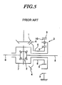
- the efficiency of the final reduction gear device may be improved by using a zero offset intersecting axis gear, or in other words a so-called bevel gear or spiral bevel gear (1), in place of the hypoid gear and interposing a speed reduction mechanism portion (3) employing a planetary gear between the bevel gear (1) and a differential gear mechanism portion (2) (see Japanese Unexamined Patent Application Publication S64-6548 which discloses the preamble of independent claim 1, for example).
- the housing (6) may be formed such that it is supported on one of the left and right output shafts (8), (8), as shown in Fig. 5 , thereby increasing the compactness of the final reduction gear device.
- the bevel ring gear (4) and an internal gear (9) of the speed reduction mechanism portion (3) are supported in a cantilevered fashion, and therefore, unless the support rigidity of the bevel ring gear (4) and the internal gear (9) is improved, the rotation of the bevel ring gear (4) becomes unstable during power transmission, leading to tooth bearing defects, defects in the alignment of a planetary gear (10) of the speed reduction mechanism portion (3) and so on, a degradation in efficiency, and the generation of noise.
- the present invention has been designed in consideration of these circumstances, and it is an object thereof to provide a final reduction gear device that is capable of improving efficiency and reducing noise generation by stabilizing the tooth bearing of various gears, while remaining compact.
- a first invention is a final reduction gear device in which a rotary drive force transmitted from an input shaft is deflected in an axis of rotation by an orthogonal axis gear, an output gear of which is disposed coaxially with a differential case of a differential gear mechanism portion, then transmitted to the differential case via a speed reduction mechanism portion that is disposed coaxially with the differential case and includes a sun gear, which is provided as a continuation of the output gear of the orthogonal axis gear and allocated to input, an internal gear which is fixed, and a planetary carrier which is allocated to output, and then transmitted to left and right output shafts by a differential pinion that rotates in the interior of the differential case integrally with the differential case, and a differential side gear that meshes with the differential pinion.
- a first bearing member having a large radial load capacity is disposed between the output gear of the orthogonal axis gear and the differential case
- a second bearing member having a large axial load capacity is disposed between the sun gear, and an inner race of the first bearing member and the differential case
- a third bearing member having a large axial load capacity is disposed between the output gear of the orthogonal axis gear and the planetary carrier.
- the radial load that acts on the output gear of the orthogonal axis gear during power transmission is received by the first bearing member, and the axial load is distributed between the first and second bearing members.
- the support rigidity of the output gear of the orthogonal axis gear can be increased without increasing the size and weight of the final reduction gear device.
- shaft wobbling during rotation of the output gear of the orthogonal axis gear is eliminated, the rotation is stabilized, and tooth bearing defects are prevented, and therefore tooth contact noise in the orthogonal axis gear can be reduced greatly.
- a spigot portion is formed on an outer peripheral surface portion of a holding member for holding a fourth bearing member, which is attached to a case main body forming an outer shell of the final reduction gear device and supports the differential case rotatably, a fitting portion that is fitted to the spigot portion is formed in the internal gear, and the internal gear is fixed to the case main body with the fitting portion fitted to the spigot portion.
- the internal gear is fixed to the case main body after improving the positioning precision and support rigidity thereof by fitting the fitting portion thereof to the spigot portion of the holding member.
- the alignment performance and support rigidity of the internal gear relative to the left and right output shafts and a planetary gear can be further improved, enabling an improvement in meshing precision and a reduction in tooth contact noise among the various gears of the speed reduction mechanism portion.
- the support rigidity of a bevel ring gear and an internal gear can be improved without increasing the size of a case main body, and therefore an efficient final reduction gear device that is capable of reducing tooth bearing defects among various gears during power transmission and reducing alignment defects in a planetary gear mechanism can be provided.
- FIG. 1 is a sectional view showing an embodiment of the final reduction gear device
- Fig. 2 is a side view of Fig. 1 .
- a final reduction gear device 11 comprises an orthogonal axis gear 12, a speed reduction mechanism portion 13 employing a planetary gear, and a differential gear mechanism portion 14.
- FIGs. 1 and 2 show a state in which the final reduction gear device 11 is disposed in a transmission case 15 serving as a case main body that is provided as a continuation of a longitudinal engine, not shown in the drawings.
- the lower side and upper side of the paper surface indicate the front and rear, respectively, while in Fig. 2 , the right side of the drawing indicates the front side.
- the orthogonal axis gear 12 comprises a bevel pinion gear 121, and a bevel ring gear 122 that meshes with the bevel pinion gear 121.
- the bevel pinion gear 121 is provided integrally with a front end portion of an input shaft 16 that is supported rotatably on the transmission case 15 forming the outer shell of the final reduction gear device 11.
- the bevel ring gear 122 is disposed coaxially with a differential case 141 of the differential gear mechanism portion 14 in a diametrical direction thereof.
- the speed reduction mechanism portion 13 comprises a sun gear 131 provided as an integral continuation of the bevel ring gear 122 and supported to be capable of rotating relative to the differential case 141, an internal gear 132 fixed to the transmission case 15, a planetary gear 133 that meshes with the sun gear 131 and the internal gear 132, and a planetary carrier 134 that supports the planetary gear 133 rotatably and is provided as an integral continuation of the differential case 141.
- the differential gear mechanism portion 14 comprises the differential case 141, to which the planetary carrier 134 is connected integrally and which is supported rotatably on the transmission case 15, a pinion shaft 143 that is fixed in a retained fashion within the differential case 141 by a straight pin 142, a pair of differential bevel pinions 144, 144 serving as differential pinions that are supported rotatably on the pinion shaft 143, and a left-right pair of differential bevel gears 145, 145 that mesh with the differential bevel pinions 144, 144 and serve as differential side gears provided as a continuation of left and right output shafts 17, 18.
- the input shaft 16 is a power transmission shaft for transmitting the rotary drive force of an engine or the like, an output side (bevel gear side) 16a of which is supported rotatably via an angular ball bearing 19 (back-to-back duplex bearing) disposed between left and right support portions 15a, 15b in the transmission case 15.
- the angular ball bearing 19 is employed because it is suitable for receiving a combined load of an axial load and a radial load and exhibits high moment rigidity.
- an axial center direction of the input shaft 16 is orthogonal to an axial center direction of the left and right output shafts 17, 18, and an axial end portion of the output side 16a of the input shaft 16 is disposed in the vicinity of the left side output shaft 17.
- the bevel pinion gear 121 is formed integrally with the axial end portion of the output side 16a of the input shaft 16.
- the bevel ring gear 122 that meshes with the bevel pinion gear 121 is provided as an integral continuation of the sun gear 131 via a linking member 123. Note that here, the linking member 123 is considered to be a part of the bevel ring gear 122.
- the bevel ring gear 122 is supported so as to be capable of rotating relative to the differential case 141 via a radial bearing 20 serving as a first bearing member, a thrust bearing 21 serving as a second bearing member, and a bush 22. Further, a thrust bearing 23 serving as a third bearing member is interposed between the bevel ring gear 122 and the planetary carrier 134.
- an outer peripheral portion of the linking member 123 is formed with a fixing portion 124 for fixing the bevel ring gear 122 to the linking member 123 using a plurality of fixing bolts 24 when joined to a back surface and an inner peripheral surface of the bevel ring gear 122.
- the fixing portion 124 comprises a back plate portion 124a and a seat surface portion 124b.
- the back plate portion 124a is formed with evenly distributed holes 124a1 (only one of which is shown in Fig. 1 ) through which the fixing bolts 24 are passed, and the bevel ring gear 122 is formed with screw holes 122a into which the fixing bolts 24 passed through the evenly distributed holes 124a1 are screwed.
- the bevel ring gear 122 is inserted into the outer peripheral side of the seat surface portion 124b, and the outer race of a bearing member that has a large radial load capacity and is therefore suited to heavy loads, for example the radial bearing 20 (which is preferably a cylindrical roller bearing), is fitted into the inner peripheral side of the seat surface portion 124b, or in other words the surface side opposing the differential case.
- the inner race of the radial bearing 20 is fitted into a fitting portion 141a formed as a recess in the outer peripheral surface of the differential case 141.
- the radial bearing 20 is disposed in the diametrical direction of the bevel ring gear 122, i.e.
- the radial bearing 20 is not limited to a cylindrical roller bearing alone, and other roller bearings, for example a tapered roller bearing, a self-aligning roller bearing, or a needle roller bearing, may be used. Alternatively, a ball bearing such as a deep groove ball bearing or an angular ball bearing may be used. Further, the number of rows of rolling bodies is not limited to a single row, and a plurality of rows may be provided. Furthermore, as long as the bearing member is capable of receiving a radial load, a thrust bearing may be used instead.
- the thrust bearings 21, 23 are disposed so as to sandwich the linking member 123 from the left and right, and therefore the thrust bearing 23 receives an axial load (thrust load) acting on the linking member 123, or in other words the bevel ring gear 122, in the left-right direction of Fig. 1 , while the thrust bearing 21 receives an axial load acting on the linking member 123 in the right-left direction of Fig. 1 .
- the thin tubular bush 22, which serves as a bearing member having a radial load capacity, is interposed between opposing surfaces of the sun gear 131 and the differential case 141.
- the axial load that acts on the bevel ring gear 122 during power transmission is dispersed between the thrust bearings 21, 23, while the radial load that acts on the sun gear 131 is received by the bush 22.
- the support rigidity of the bevel ring gear 122 is further enhanced, and tooth contact noise between the bevel pinion gear 121 and bevel ring gear 122 is reduced.
- thrust bearings 21, 23 may be either thrust ball bearings (for example, thrust angular ball bearings) or thrust roller bearings (for example, thrust cylindrical roller bearings, thrust needle roller bearings, and thrust tapered roller bearings) .
- thrust ball bearings for example, thrust angular ball bearings
- thrust roller bearings for example, thrust cylindrical roller bearings, thrust needle roller bearings, and thrust tapered roller bearings
- a radial bearing may be used instead.
- the speed reduction mechanism portion 13 employs a single pinion-type planetary gear mechanism in which the sun gear 131 provided as a continuation of the bevel ring gear 122 is allocated to input, the internal gear 132 is fixed, and the planetary carrier 134 is allocated to output.
- the planetary gear 133 which meshes with the sun gear 131 and internal gear 132, is supported rotatably by the planetary carrier 134, and the planetary carrier 134 is provided as an integral continuation of the outer peripheral surface of the differential case 141 by means of a spline engagement.
- the speed reduction mechanism portion 13 decreases a rotational speed input from the sun gear 131 using a speed reduction ratio (a+c) /a set in accordance with a number of teeth a of the sun gear 131 and a number of teeth c of the internal gear 132, and transmits the decreased rotational speed to the differential case 141. Furthermore, the speed reduction mechanism portion 13 is formed such that the planetary carrier 134 rotates in an identical direction to the rotational direction of the sun gear 131.
- speed reduction mechanism portion 13 employs a single pinion-type planetary gear mechanism, it is not limited thereto, and may employ a double pinion-type planetary gear mechanism.
- the internal gear 132 comprises a fitting portion 132b that extends from a gear main body portion 132a, which meshes with the planetary gear 133, so as to be joined like a socket and spigot joint, or in other words positioned and held with a high degree of precision, to a left end portion of an axle holder 25 serving as a holding member on the right side of Fig. 1 , and two fixing flange portions 132c, 132c (shown in Fig. 2 ) provided on the outer peripheral side of the fitting portion 132b for bolting the internal gear to the transmission case.
- the fitting portion 132b When the axle holder 25 is fitted into the fitting potion 132b, the fitting portion 132b is formed with an L-shaped cross-section so as to be ring-shaped when seen from the side, thereby blocking the axle holder side of the internal gear 132. Further, the fitting portion 132b is provided with an oil passage 132d so that lubricating oil can pass between the axle holder side and the planetary carrier side of the fitting portion 132b.
- An oil passage 134a is also formed in the interior of the planetary carrier 134, and therefore the lubricating oil that passes through these oil passages 132d, 134a is capable of lubricating not only a sliding portion between the planetary gear 133 and planetary carrier 134, but also a meshing surface between the internal gear 132 and planetary gear 133 and a meshing surface between the sun gear 131 and planetary gear 133.
- bolt holes 132e, 132e through which fixing bolts 27, 27 pass are formed in the respective centers of the two fixing flange portions 132c, 132c, and a central position of each bolt hole 132e substantially matches an outer peripheral radius of the internal gear 132.
- the two fixing flange portions 132c, 132c are provided at a 180 degree interval such that a height difference is provided therebetween, and the high side fixing flange portion 132c is positioned further toward the front side (engine side) than the low side fixing flange portion 132c.
- the axle holder 25 is interposed between the transmission case 15 and the outer race of a single row angular ball bearing 26 serving as a fourth bearing member for supporting the differential case 141 rotatably.
- a spigot portion 25a is provided on one end portion (the bevel ring gear side) of the axle holder 25 so as to extend along the outer race of the single row angular ball bearing 26.
- the inner race of the single row angular ball bearing 26 is disposed so as to receive the axial load that acts on the planetary carrier 134.
- the bearing member is not limited to a single row angular ball bearing alone, and another bearing member may be used as long as the bearing member is capable of receiving a radial load, an axial load, and a combined load thereof.
- a drive force transmitted to the differential case 141 is transmitted from the pinion shaft 143 to the pair of differential bevel pinions 144, 144, and then transmitted from the pair of differential bevel gears 145, 145 that mesh with the differential bevel pinions 144, 144 to the left and right output shafts 17, 18.
- left and right drive wheels not shown in the drawings, rotate.
- the radial load that acts on the bevel ring gear 122 of the orthogonal axis gear 12 during power transmission is received by the radial bearing 20, while the axial load is distributed between the thrust bearings 21, 23.
- the support rigidity of the bevel ring gear 122 can be increased without increasing the size and weight of the final reduction gear device 11.
- shaft wobbling during rotation of the bevel ring gear 122 is eliminated, the rotation is stabilized, and tooth bearing defects are prevented, and therefore tooth contact noise in the orthogonal axis gear 12 can be reduced greatly.
- the positioning precision and support rigidity of the internal gear 132 are improved by fitting the fitting portion 132b thereof to the spigot portion 25a of the axle holder 25, and thus the internal gear 132 is bolted rigidly to the transmission case 15.
- the support rigidity and alignment performance of the internal gear 132 can be improved, enabling an improvement in meshing precision and a reduction in tooth contact noise among the various gears 131 to 133 of the speed reduction mechanism portion 13.
- a zero offset bevel gear is used as the orthogonal axis gear 12, but the present invention is not limited thereto, and a near-zero offset hypoid gear (a skew gear) may be used instead.
- this embodiment may be applied to a final reduction gear device that employs parallel axis gears as well as a final reduction gear device employing an orthogonal axis gear. This embodiment may also be applied to a rear differential device.
Landscapes
- Engineering & Computer Science (AREA)
- Chemical & Material Sciences (AREA)
- Combustion & Propulsion (AREA)
- Transportation (AREA)
- Mechanical Engineering (AREA)
- General Details Of Gearings (AREA)
- Retarders (AREA)
- Gear Transmission (AREA)
- Motor Power Transmission Devices (AREA)
- Rolling Contact Bearings (AREA)
Claims (2)
- Enduntersetzungsgetriebevorrichtung (11), bei der eine von einer Antriebswelle (16) übertragene Drehantriebskraft in einer Drehachse durch ein Orthogonalachsenzahnrad (12) abgelenkt wird, von dem ein Abtriebszahnrad (122) koaxial mit einem Differentialgehäuse (141) eines Differentialgetriebemechanismusabschnitt (14) angeordnet ist, dann auf das Differentialgehäuse (141) über einen Drehzahlminderungsmechanismusabschnitt (13), der koaxial mit dem Differentialgehäuse angeordnet ist und ein Sonnenrad (131) umfasst, das als Fortsetzung des Abtriebszahnrads des Orthogonalachsenzahnrads vorgesehen und dem Antrieb zugeordnet ist, ein Innenzahnrad (132), das feststeht, und einen Planetenträger (134), der dem Abtrieb zugeordnet ist, übertragen wird, und dann auf eine linke und rechte Abtriebswelle (17, 18) über ein Differentialritzel (144), das sich im Inneren des Differentialgehäuses integral mit dem Differentialgehäuse dreht, und auf ein differentialseitiges Zahnrad (145) übertragen wird, das mit dem Differentialritzel dreht,
dadurch gekennzeichnet, dass
ein erstes Lagerteil (20) mit einer großen Radiallasttragfähigkeit zwischen dem Abtriebszahnrad (122) des Orthogonalachsenzahnrads (12) und dem Differentialgehäuse (141) angeordnet ist, ein zweites Lagerteil (21) mit einer großen Axiallasttragfähigkeit zwischen dem Sonnenrad und einer inneren Lauffläche des ersten Lagerteils und dem Differentialgehäuse angeordnet ist, und ein drittes Lagerteil (23) mit einer großen Axiallasttragfähigkeit zwischen dem Abtriebszahnrad des Orthogonalachsenzahnrads und dem Planetenträger (134) vorgesehen ist. - Enduntersetzungsgetriebevorrichtung nach Anspruch 1, wobei ein Zapfenabschnitt (25a) an einem Außenumfangsflächenabschnitt eines Halteteils (25) zum Haltern eines vierten Lagerteils (26) ausgebildet ist, das an einem Gehäusehauptkörper (15) angebracht ist, der eine Außenhülle der Enduntersetzungsgetriebevorrichtung bildet und das Differentialgehäuse drehbar lagert,
ein Einpassabschnitt (132), der in den Zapfenabschnitt eingepasst ist, in dem Innenzahnrad ausgebildet ist, und
das Innenzahnrad am Gehäusehauptkörper mit dem in den Zapfenabschnitt eingepassten Einpassabschnitt befestigt ist.
Applications Claiming Priority (1)
| Application Number | Priority Date | Filing Date | Title |
|---|---|---|---|
| JP2007146986A JP4850129B2 (ja) | 2007-06-01 | 2007-06-01 | 最終減速装置 |
Publications (3)
| Publication Number | Publication Date |
|---|---|
| EP1998080A2 EP1998080A2 (de) | 2008-12-03 |
| EP1998080A3 EP1998080A3 (de) | 2010-05-12 |
| EP1998080B1 true EP1998080B1 (de) | 2011-10-26 |
Family
ID=39708018
Family Applications (1)
| Application Number | Title | Priority Date | Filing Date |
|---|---|---|---|
| EP08157035A Expired - Fee Related EP1998080B1 (de) | 2007-06-01 | 2008-05-28 | Enduntersetzungsgetriebevorrichtung |
Country Status (3)
| Country | Link |
|---|---|
| US (1) | US7988583B2 (de) |
| EP (1) | EP1998080B1 (de) |
| JP (1) | JP4850129B2 (de) |
Families Citing this family (13)
| Publication number | Priority date | Publication date | Assignee | Title |
|---|---|---|---|---|
| CN101482164B (zh) * | 2007-10-17 | 2014-06-25 | 金属达因有限责任公司 | 差速器组件及其制造方法 |
| JP4891890B2 (ja) * | 2007-12-18 | 2012-03-07 | 富士重工業株式会社 | 最終減速装置 |
| US8403798B2 (en) * | 2011-02-24 | 2013-03-26 | Ford Global Technologies, Llc | Final drive mechanism for a transmission |
| US8939862B2 (en) * | 2011-03-21 | 2015-01-27 | Ford Global Technologies, Llc | Final drive mechanism and power take off for a transmission |
| JP5816584B2 (ja) | 2012-03-23 | 2015-11-18 | 住友重機械工業株式会社 | 動力伝達装置 |
| CN102734441A (zh) * | 2012-06-27 | 2012-10-17 | 中国重汽集团济南动力有限公司 | 新型双中间轴变速箱 |
| CN103629332A (zh) * | 2012-08-21 | 2014-03-12 | 常州长浪齿轮箱有限公司 | 同向平行双螺杆超高扭矩齿轮箱 |
| DE102013201092A1 (de) * | 2013-01-24 | 2014-07-24 | Zf Friedrichshafen Ag | Antriebseinrichtung für die Laufräder eines Fahrzeugs |
| CN104315111A (zh) * | 2014-10-17 | 2015-01-28 | 株洲高精传动技术有限公司 | 齿轮传动轴装置 |
| DE102016216799B4 (de) * | 2016-09-06 | 2022-10-13 | Schaeffler Technologies AG & Co. KG | Stirnraddifferenzial mit zerstörungsfrei demontierbaren Sonnenrädern |
| US20180163795A1 (en) * | 2016-12-11 | 2018-06-14 | Bell Helicopter Textron, Inc. | Drivetrain subassembly having an integrated sprag clutch race and gear shaft member |
| US11199251B2 (en) * | 2019-12-19 | 2021-12-14 | Schaeffler Technologies AG & Co. KG | Orbitally formed hypoid pinion gear |
| CN113217601B (zh) * | 2021-06-04 | 2022-04-29 | 一汽解放汽车有限公司 | 一种减速器总成及混合驱动桥 |
Family Cites Families (19)
| Publication number | Priority date | Publication date | Assignee | Title |
|---|---|---|---|---|
| US1329319A (en) * | 1918-01-28 | 1920-01-27 | Perfecto Gear Differential Co | Driving mechanism for motor-cars |
| GB150868A (en) * | 1919-07-08 | 1920-09-16 | Perfecto Gear Differential Com | Improvements in driving mechanism for motor vehicles |
| FR1144205A (fr) * | 1955-04-29 | 1957-10-10 | Eaton Axles Ltd | Perfectionnements aux essieux moteurs à deux vitesses |
| US4227427A (en) * | 1977-09-08 | 1980-10-14 | Dana Corporation | Drive unit assembly |
| JPS55163364A (en) * | 1979-06-02 | 1980-12-19 | Nissan Diesel Motor Co Ltd | Lubricating device of differential reduction gear for vehicle |
| IT1155495B (it) * | 1982-04-05 | 1987-01-28 | Sirp Spa | Sistema di trasmissione per autoveicoli |
| JPS5957032A (ja) * | 1982-09-27 | 1984-04-02 | Mazda Motor Corp | 四輪駆動車 |
| US4817753A (en) * | 1986-09-02 | 1989-04-04 | Mazda Motor Corporation | Interaxle differential restriction device for vehicle four wheel drive systems |
| JP2502565B2 (ja) * | 1987-02-23 | 1996-05-29 | マツダ株式会社 | 車両用動力伝達装置 |
| JPS646548A (en) * | 1987-06-29 | 1989-01-11 | Komatsu Mfg Co Ltd | Differential gear device |
| JP3099331B2 (ja) * | 1989-07-04 | 2000-10-16 | トヨタ自動車株式会社 | 車輌用駆動装置 |
| JPH05332401A (ja) * | 1992-05-27 | 1993-12-14 | Toyota Motor Corp | 電気自動車用減速装置 |
| AT406851B (de) * | 1994-08-03 | 2000-10-25 | Steyr Daimler Puch Ag | Verteilergetriebe mit koaxialen abtriebswellen und einem schaltbaren gruppengetriebe |
| US5695426A (en) * | 1994-08-03 | 1997-12-09 | Steyr-Daimler-Puch Aktiengesellschaft | Automotive transmission apparatus |
| JPH11166609A (ja) * | 1997-09-30 | 1999-06-22 | Aisin Seiki Co Ltd | トランスアクスル |
| JP3646084B2 (ja) * | 2001-10-22 | 2005-05-11 | 富士重工業株式会社 | 車両の駆動装置 |
| ITPD20020224A1 (it) * | 2002-09-03 | 2004-03-04 | Carraro Spa | Assale perfezionato per veicoli particolarmente per |
| JP5001538B2 (ja) | 2005-08-01 | 2012-08-15 | 富士重工業株式会社 | 動力分配装置 |
| JP2007146986A (ja) | 2005-11-29 | 2007-06-14 | Yoshinobu Wada | 自転車用変速装置 |
-
2007
- 2007-06-01 JP JP2007146986A patent/JP4850129B2/ja not_active Expired - Fee Related
-
2008
- 2008-05-28 EP EP08157035A patent/EP1998080B1/de not_active Expired - Fee Related
- 2008-05-29 US US12/128,881 patent/US7988583B2/en not_active Expired - Fee Related
Also Published As
| Publication number | Publication date |
|---|---|
| EP1998080A2 (de) | 2008-12-03 |
| JP2008298231A (ja) | 2008-12-11 |
| JP4850129B2 (ja) | 2012-01-11 |
| US20080300085A1 (en) | 2008-12-04 |
| EP1998080A3 (de) | 2010-05-12 |
| US7988583B2 (en) | 2011-08-02 |
Similar Documents
| Publication | Publication Date | Title |
|---|---|---|
| EP1998080B1 (de) | Enduntersetzungsgetriebevorrichtung | |
| US6814684B2 (en) | Planetary gear | |
| US5324240A (en) | Eccentric gear system | |
| US8007391B2 (en) | Differential apparatus for vehicle | |
| US6117038A (en) | Power transmission device | |
| US6780136B2 (en) | Combined differential gear device | |
| US20020055408A1 (en) | Infinitely variable transmission | |
| GB2573638A (en) | Epicyclic gearbox | |
| JP4782341B2 (ja) | 遊星変速機において動力を分担する歯車装置 | |
| JP4891890B2 (ja) | 最終減速装置 | |
| WO2001031231A1 (en) | Gearing for power sharing in planetary transmission | |
| US10487933B2 (en) | Axle assembly having ring gear with unitarily and integrally formed portion of a bearing race | |
| CN111288150A (zh) | 一种减速驱动系统及一种电动汽车 | |
| KR100339845B1 (ko) | 감속기 | |
| JP2003048441A (ja) | 車両用四輪駆動装置 | |
| JP2021113606A (ja) | 動力伝達装置 | |
| EP4141287A1 (de) | Getriebemechanismus | |
| US11536363B2 (en) | Vehicle driveline component having a housing with a lube feed ramp for providing increased lubrication to a bearing that supports a pinion | |
| CN214007970U (zh) | 一种外啮合行星齿轮机构的双联行星齿轮结构 | |
| US20230265917A1 (en) | Gear unit for an electric drive system of a motor vehicle and electric drive system with such a gear unit | |
| CN116194687A (zh) | 减速装置和电气设备 | |
| CN115750689A (zh) | 少齿差行星减速器 | |
| KR20230063530A (ko) | 유압모터용 감속기 | |
| JP2020118203A (ja) | 差動装置 | |
| JP2018135976A (ja) | 差動装置 |
Legal Events
| Date | Code | Title | Description |
|---|---|---|---|
| PUAI | Public reference made under article 153(3) epc to a published international application that has entered the european phase |
Free format text: ORIGINAL CODE: 0009012 |
|
| AK | Designated contracting states |
Kind code of ref document: A2 Designated state(s): AT BE BG CH CY CZ DE DK EE ES FI FR GB GR HR HU IE IS IT LI LT LU LV MC MT NL NO PL PT RO SE SI SK TR |
|
| AX | Request for extension of the european patent |
Extension state: AL BA MK RS |
|
| PUAL | Search report despatched |
Free format text: ORIGINAL CODE: 0009013 |
|
| AK | Designated contracting states |
Kind code of ref document: A3 Designated state(s): AT BE BG CH CY CZ DE DK EE ES FI FR GB GR HR HU IE IS IT LI LT LU LV MC MT NL NO PL PT RO SE SI SK TR |
|
| AX | Request for extension of the european patent |
Extension state: AL BA MK RS |
|
| RIC1 | Information provided on ipc code assigned before grant |
Ipc: B60K 17/16 20060101AFI20100406BHEP Ipc: F16H 48/08 20060101ALN20100406BHEP |
|
| 17P | Request for examination filed |
Effective date: 20101110 |
|
| AKX | Designation fees paid |
Designated state(s): DE |
|
| RIC1 | Information provided on ipc code assigned before grant |
Ipc: B60K 17/16 20060101AFI20110104BHEP Ipc: F16H 48/08 20060101ALN20110104BHEP |
|
| GRAP | Despatch of communication of intention to grant a patent |
Free format text: ORIGINAL CODE: EPIDOSNIGR1 |
|
| GRAS | Grant fee paid |
Free format text: ORIGINAL CODE: EPIDOSNIGR3 |
|
| GRAA | (expected) grant |
Free format text: ORIGINAL CODE: 0009210 |
|
| RIN1 | Information on inventor provided before grant (corrected) |
Inventor name: HIRASE, HIROMIC/O FUJI JUKOGYO KABUSHIKI KAISHA |
|
| AK | Designated contracting states |
Kind code of ref document: B1 Designated state(s): DE |
|
| REG | Reference to a national code |
Ref country code: DE Ref legal event code: R096 Ref document number: 602008010764 Country of ref document: DE Effective date: 20120126 |
|
| PLBE | No opposition filed within time limit |
Free format text: ORIGINAL CODE: 0009261 |
|
| STAA | Information on the status of an ep patent application or granted ep patent |
Free format text: STATUS: NO OPPOSITION FILED WITHIN TIME LIMIT |
|
| 26N | No opposition filed |
Effective date: 20120727 |
|
| REG | Reference to a national code |
Ref country code: DE Ref legal event code: R097 Ref document number: 602008010764 Country of ref document: DE Effective date: 20120727 |
|
| PGFP | Annual fee paid to national office [announced via postgrant information from national office to epo] |
Ref country code: DE Payment date: 20160524 Year of fee payment: 9 |
|
| REG | Reference to a national code |
Ref country code: DE Ref legal event code: R082 Ref document number: 602008010764 Country of ref document: DE Representative=s name: MEISSNER BOLTE PATENTANWAELTE RECHTSANWAELTE P, DE Ref country code: DE Ref legal event code: R081 Ref document number: 602008010764 Country of ref document: DE Owner name: SUBARU CORPORATION, JP Free format text: FORMER OWNER: FUJI JUKOGYO K.K., TOKIO/TOKYO, JP |
|
| REG | Reference to a national code |
Ref country code: DE Ref legal event code: R119 Ref document number: 602008010764 Country of ref document: DE |
|
| PG25 | Lapsed in a contracting state [announced via postgrant information from national office to epo] |
Ref country code: DE Free format text: LAPSE BECAUSE OF NON-PAYMENT OF DUE FEES Effective date: 20171201 |