EP1210495B1 - Verfahren zum bewehren eines gebäudes - Google Patents
Verfahren zum bewehren eines gebäudes Download PDFInfo
- Publication number
- EP1210495B1 EP1210495B1 EP00958800A EP00958800A EP1210495B1 EP 1210495 B1 EP1210495 B1 EP 1210495B1 EP 00958800 A EP00958800 A EP 00958800A EP 00958800 A EP00958800 A EP 00958800A EP 1210495 B1 EP1210495 B1 EP 1210495B1
- Authority
- EP
- European Patent Office
- Prior art keywords
- wall
- rod
- drilling
- frame
- sections
- Prior art date
- Legal status (The legal status is an assumption and is not a legal conclusion. Google has not performed a legal analysis and makes no representation as to the accuracy of the status listed.)
- Expired - Lifetime
Links
- 238000000034 method Methods 0.000 title claims description 29
- 230000003014 reinforcing effect Effects 0.000 title claims description 28
- 238000005553 drilling Methods 0.000 claims abstract description 34
- 239000011440 grout Substances 0.000 claims abstract description 20
- 239000004744 fabric Substances 0.000 claims abstract description 18
- 230000002787 reinforcement Effects 0.000 claims abstract description 10
- 230000008878 coupling Effects 0.000 claims description 16
- 238000010168 coupling process Methods 0.000 claims description 16
- 238000005859 coupling reaction Methods 0.000 claims description 16
- 238000003491 array Methods 0.000 claims description 2
- 239000012466 permeate Substances 0.000 claims description 2
- 239000011449 brick Substances 0.000 description 6
- 239000004567 concrete Substances 0.000 description 4
- 239000011150 reinforced concrete Substances 0.000 description 4
- 230000000712 assembly Effects 0.000 description 3
- 238000000429 assembly Methods 0.000 description 3
- 238000010276 construction Methods 0.000 description 2
- 239000011521 glass Substances 0.000 description 2
- 239000002184 metal Substances 0.000 description 2
- 230000035939 shock Effects 0.000 description 2
- 238000005253 cladding Methods 0.000 description 1
- 239000002131 composite material Substances 0.000 description 1
- 238000004880 explosion Methods 0.000 description 1
- 238000002347 injection Methods 0.000 description 1
- 239000007924 injection Substances 0.000 description 1
- 238000003780 insertion Methods 0.000 description 1
- 230000037431 insertion Effects 0.000 description 1
- 239000011159 matrix material Substances 0.000 description 1
- 230000000750 progressive effect Effects 0.000 description 1
- 238000009416 shuttering Methods 0.000 description 1
- 238000000638 solvent extraction Methods 0.000 description 1
- 238000005728 strengthening Methods 0.000 description 1
- 230000002459 sustained effect Effects 0.000 description 1
Images



Classifications
-
- E—FIXED CONSTRUCTIONS
- E06—DOORS, WINDOWS, SHUTTERS, OR ROLLER BLINDS IN GENERAL; LADDERS
- E06B—FIXED OR MOVABLE CLOSURES FOR OPENINGS IN BUILDINGS, VEHICLES, FENCES OR LIKE ENCLOSURES IN GENERAL, e.g. DOORS, WINDOWS, BLINDS, GATES
- E06B1/00—Border constructions of openings in walls, floors, or ceilings; Frames to be rigidly mounted in such openings
- E06B1/56—Fastening frames to the border of openings or to similar contiguous frames
- E06B1/60—Fastening frames to the border of openings or to similar contiguous frames by mechanical means, e.g. anchoring means
- E06B1/6015—Anchoring means
- E06B1/6038—Anchoring means specially adapted for being embedded in the wall
-
- E—FIXED CONSTRUCTIONS
- E04—BUILDING
- E04G—SCAFFOLDING; FORMS; SHUTTERING; BUILDING IMPLEMENTS OR AIDS, OR THEIR USE; HANDLING BUILDING MATERIALS ON THE SITE; REPAIRING, BREAKING-UP OR OTHER WORK ON EXISTING BUILDINGS
- E04G23/00—Working measures on existing buildings
- E04G23/02—Repairing, e.g. filling cracks; Restoring; Altering; Enlarging
- E04G23/0218—Increasing or restoring the load-bearing capacity of building construction elements
Definitions
- This invention relates to the reinforcement of build ings, particularly some time after their original construction.
- the tying of the rods is never particularly strong, and these are one of the weak points in the building.
- the concrete columns in the building described above can be reinforced by this defined method, the centre of each column being generally free of reinforcing rod and therefore susceptible to being drilled without interference. It may also be possible to insert horizontal reinforcements and diagonal ones, across infulls between columns. The basic structure can therefore be made substantially stronger than it was originally.
- a method of reinforcing the anchorage of a frame in an aperture in the wall of a building comprising making a first drilling into the reveals of the aperture from within the aperture, the drilling being between the inner and outer faces of the wall, inserting a reinforcing rod enveloped by a loose fabric sleeve into the first drilling, the proximal end of the rod being secured or securable to a frame within the aperture, and inserting grout to expand the sleeve against the wall of the associated first drilling to penetrate through the fabric and bond to the wall, characterised in that the rod is curved back on itself at the distal end from the frame to form a loop, and the plane of the loop is substantially at right handles to the wall, and in that a second drilling is made into the wall between its two faces when the grout has set so that the drill bit passes through the loop, an extra reinforcing rod enveloped by a loose fabric sleeve is inserted into the second drilling, and grout is
- the rod is curved back on itself at the distal end from the frame to form a loop.
- the loop may be open so that the rod is of thin J-shape, but preferably the rod is of thin U-shape with both ends proximal to and secured or securable to the frame.
- the wall When the plane of a single loop anchorage is substantially at right angles to the wall, and when the grout has set, the wall may be drilled between its two faces so that the drill bit passes through the loop. Then an extra reinforcing rod enveloped by a loose fabric sleeve can be inserted in the drilling and grout injected to expand that sleeve against the wall of the drilling, also permeating through the fabric to bond to the wall. And when the aperture has a plurality of looped frame reinforcements along at least one side, the loops can be aligned to receive a common extra reinforcing rod.
- a structure has an array of apertures with a corresponding set of aligned sides. With each such side having at least one looped frame reinforcement, a common extra reinforcing rod can be passed through all the loops associated with a set of aligned sides. And when there are two parallel arrays of apertures, the looped frame reinforcements of adjacent parallel sets of sides may overlap to be threaded by a common extra reinforcing rod.
- reinforcing rod for the defined method, the rod being composed of a plurality of sections coupled by energy absorbing means that fail at a predetermined critical load.
- the critical loads of the couplings need not be uniform throughout the rod. Some can be arranged to give way earlier than others so that there can be progressive and relatively controlled failure of the structure.
- two adjacent sections may overlap and be strapped together by an encircling element, or the overlapping portions could be transversely drilled to receive a shear pin.
- two adjacent sections can hook around a hollow member from opposite directions, this member crumpling when the critical load is applied.
- a further possibility is for two adjacent sections to hook directly together, at least one hook being designed to straighten and thus release when the critical load is applied.
- one of two adjacent sections has a throat through which an end of the other of said two sections passes, that end having an enlargement beyond the throat which normally maintains the sections coupled. But when the critical load is applied the enlargement is capable of forcing its way through the throat.
- At least one coupling can differ from another, the different couplings being selected for example from those outlined above.
- the energy absorbing couplings When a wall is reinforced by such a multi-section rod and is non-uniform and has relatively weak and strong portions through which the rod passes, the energy absorbing couplings will generally be in the weak portions.
- a typical example is a reinforced concrete frame building with brick infills. The couplings would be within the brick to control the disintegration in the face of blast or seismic shock.
- the frame could be further reinforced using the defined method, the vertical and horizontal members being drilled to receive sleeved reinforcing rods subsequently encased by grout.
- FIG. 1 shows a window anchorage comprising a reinforcing bar 10, a fabric sleeve 11 encasing all but one end of the bar, a plate 12 and a nut 13 threaded on that one end.
- the other end is bent back so that the bar assumes the shape of a narrow J.
- the bar 10 is slightly cranked so that the axis of the nut 13 is aligned with the centre of the bight of the J.
- the anchorage may be secured without the plate 12 or nut 13; they may be fitted only after the grout has set.
- the frame will largely dictate how this is done and it will be understood that the plates 12 may actually be part of the frame, and could have a more complex shape.
- the frame members could have a square U-shaped cross-section, the web of the U being outermost (in relation to the wall) and the outer limbs (in relation to the aperture) being notched to fit over the projecting bars 10.
- the nuts 13 would then be tightened against the inside of the outer limbs to clamp the frame in place.
- the plates 12 could have flanges projecting into the aperture, against which the frame can be abutted and secured.
- the ends of the bars 10 projecting beyond the nuts 13 could be trimmed off and the flanges would be deeper than the thickness of the nuts. This would leave only a narrow gap around the frame to be covered or filled in.
- the filling could be similar to the anchorage, with grout being injected to fill a fabric sleeve surrounding the frame.
- a further arrangement to allow the frame to fit even more closely into the aperture, eliminates the nut 13 and the projecting end of the bar 10. Instead the bar is wholly within the drilling and presents a screw-threaded socket in its end face, which will be substantially flush with the reveal.
- the frame is drilled at points to register with these sockets and, when correctly in place, screw bolts are entered through the frame and tightened into the bars 10.
- the bars 10 may be put with their sleeves 11 loosely into the drillings, offer up the frame and secure that to the bars, and then inject grout simultaneously into all the anchorages via tubes extending through the frame if necessary but preferably between the frame and the reveals.
- Figures 2 and 3 show a variation on the anchorage of Figure 1 where two overlapping drillings are made, and a reinforcing rod 17, again encased in a sleeve 18 for grout injection, is of elongate U-form with its two free ends extending through a plate 19 and fitted with nuts 20.
- Figure 6 shows a window secured by four anchorages of the type shown in Figures 2 and 3.
- Figure 7 shows a rectangular matrix array of such windows. Because of their spacing, the positions of the anchorages have to be staggered, as they overlap within the wall. Although shown with their planes vertical, in practice each anchorage will preferably be turned at right angles so that the plane of each U will be horizontal. The wall may then be drilled vertically, the drillings passing down through the limbs of the U-shaped bars. The drill bit is then replaced by a reinforcing rod 26 encased in a fabric sleeve as described above. When grouting is complete, the anchorages are positively linked or hooked to these rods, and the entire set of windows is a cohesive network.
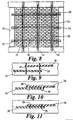
- a reinforced concrete frame 31 has a brick infill panel 32. This is further reinforced by making drillings in a grid pattern, inserting rod assemblies 33, each encased in a fabric sleeve 34, into the drillings, and injecting grout to expand and fill the sleeves. Some of the grout seeps through to bond to the bricks and concrete.
- the rod assemblies 33 in this example each comprise short rods 35 attached in overlapping manner to the opposite ends of main rods 36.
- the overlaps coincide with the discontinuities between frame 31 and panel 32, but it will be understood that they can be anywhere along the rod assemblies 33 and there could be several for each assembly (that is each rod 36 could be a composite).
- the rods 35 and 36 are mutually fastened by straps 38. These may be several turns of wire, for example, designed to unravel or part at a particular load. Or they may be metal rings crimped into a figure-of-eight around the rods.
- the end of the rod 35 is formed as a hook 40 and the end of the rod 36 is formed as an eye 41 in which the hook 40 engages. At a certain load, the eye 41 pulls the hook straight or at least bends it so that rod 36 is released.
- the end of the rod 35 is formed into an eye 42, and the end of the rod 36 is formed into a clevis 43 into which the eye 42 can enter.
- the two limbs of the clevis are apertured and through them and the eye 42 is entered a hollow cylindrical body 44.
- One end flange 45 can be pre-formed, and the other flange 46 may be formed after insertion, by axial pressure for example, to retain the body 44 in place.
- the body 44 will crumple, allowing the rods to move apart and eventually separate when one or both flanges 45 and 46 pull through the apertures in the clevis 43.
- the end of the rod 35 has an enlargement 47 while the end of the rod 36 has an aligned cylindrical member 48 with a bottle shaped chamber 49, the neck or throat 50 of the bottle opening away from the rod 36.
- the enlargement 47 is trapped in this chamber 49, seating into the shoulder where the neck or throat 50 begins. But when a predetermined load is sustained, the neck or throat 50 gives way and expands, allowing the enlargement 47 to escape, and/or the enlargement 50 is squeezed into a body of lesser girth with the same result.
Landscapes
- Engineering & Computer Science (AREA)
- Architecture (AREA)
- Mechanical Engineering (AREA)
- Civil Engineering (AREA)
- Structural Engineering (AREA)
- Chemical Kinetics & Catalysis (AREA)
- Chemical & Material Sciences (AREA)
- Electrochemistry (AREA)
- Working Measures On Existing Buildindgs (AREA)
- Reinforcement Elements For Buildings (AREA)
- Building Environments (AREA)
- Buildings Adapted To Withstand Abnormal External Influences (AREA)
- Devices That Are Associated With Refrigeration Equipment (AREA)
- Harvester Elements (AREA)
Claims (16)
- Verfahren zur Bewehrung der Verankerung eines Rahmens in einer Öffnung in der Wand eines Gebäudes, wobei das Verfahren die folgenden Schritte umfasst, nämlich Einbringen einer ersten Bohrung (14) in die äußeren Leibungen der Öffnung von der Öffnung aus, wobei das Bohren ausgeführt wird zwischen der inneren und der äußeren Fläche der Wand, Einführen eines Bewehrungsstabes (10, 17, 22), welcher umhüllt ist von einer losen Gewebehülse (11, 18), in die erste Bohrung, wobei das proximale Ende des Stabes befestigt oder festlegbar ist an einem Rahmen innerhalb der Öffnung, und Einführen von Mörtel zum Expandieren der Hülse gegen die Wand der zugeordneten ersten Bohrung, um das Gewebe zu durchdringen und eine Bindung zur Wand herzustellen,
dadurch gekennzeichnet, dass der Stab (10, 17) zu sich selbst hin zurückgekrümmt wird am distalen Ende von dem Rahmen zur Bildung einer Schlaufe, wobei die Ebene der Schlaufe im wesentlichen in einem rechten Winkel zur Wand angeordnet ist, dass eine zweite Bohrung in die Wand eingebracht wird zwischen ihren beiden Flächen, wenn der Mörtel ausgehärtet ist, so dass die Bohrerspitze die Schlaufe durchgreift, dass ein weiterer Bewehrungsstab (26), welcher von einer losen Gewebehülse eingeschlossen ist, in die zweite Bohrung eingebracht wird und dass Mörtel injiziert wird zum Expandieren der Hülse gegen die Wand der zweiten Bohrung, um das Gewebe zu durchdringen und eine Bindung zur Wand herzustellen. - Verfahren gemäß Anspruch 1, dadurch gekennzeichnet, dass die Schlaufe offen ist und der Stab (10) eine dünne U-Form besitzt.
- Verfahren gemäß Anspruch 1, dadurch gekennzeichnet, dass der Stab (17) eine dünne U-Form besitzt, wobei beide Enden proximal zum Rahmen und an diesem festlegbar sind.
- Verfahren gemäß Anspruch 3, dadurch gekennzeichnet, dass von ihren beiden U-förmigen Stäben (22, 23) innerhalb der gleichen Bohrung einer kürzer ist als der andere und sie mit ihren beiden Ebenen im wesentlichen in rechten Winkeln ineinandergreifen.
- Verfahren gemäß einem der vorangehenden Ansprüche, dadurch gekennzeichnet, dass die Öffnung eine Mehrzahl von geschlauften Rahmenbewehrungen entlang mindestens einer Seite besitzt, wobei die Schlaufen ausgerichtet sind zur Aufnahme eines gemeinsamen besonderen Bewehrungsstabes (26).
- Verfahren gemäß Anspruch 5, dadurch gekennzeichnet, dass ein Muster von Öffnungen vorgesehen ist mit einer entsprechende Gruppen von aufeinander ausgerichteten Seiten, jede derartige Seite mindestens eine geschlaufte Rahmenbewehrung trägt und ein gemeinsamer besonderer Bewehrungsstab (26) alle die Schlaufen durchgreift, die der Gruppe aufeinander ausgerichteten Seiten zugeordnet sind.
- Verfahren gemäß Anspruch 6, dadurch gekennzeichnet, dass zwei parallele Muster von Öffnungen vorgesehen sind, wobei sich die geschlauften Rahmenbewehrungen benachbarter paralleler Gruppen von Seiten überlappen, um durchgriffen zu werden von einem gemeinsamen besonderen Bewehrungsstab (26).
- Verfahren gemäß einem der vorangehenden Ansprüche, wobei der bei dem Verfahren eingesetzte Bewehrungsstab sich zusammensetzt aus einer Mehrzahl von Abschnitten (36, 36), die aneinander angekoppelt sind über energieaufnehmende Mittel (37, 38, 39, 40, 44, 47, 50), die bei einer vorbestimmten kritischen Belastung versagen.
- Verfahren gemäß Anspruch 8, dadurch gekennzeichnet, dass mehr als zwei Abschnitte (35, 36) in dem Bewehrungsstab vorgesehen sind und die kritischen Belastungen der Kopplungen nicht gleichförmig durch den Stab sind.
- Verfahren gemäß einem der Ansprüche 8 oder 9, dadurch gekennzeichnet, dass zwei benachbarte Abschnitte (35, 36) sich überlappen und zusammengehalten sind durch ein umgreifendes Element (37, 38), welches als energieabsorbierende Kopplung dient.
- Verfahren gemäß einem der Ansprüche 8 oder 9, dadurch gekennzeichnet, dass sich zwei benachbarte Abschnitte (35, 36) überlappen, wobei die sich überlappenden Teile quer gebohrt sind zur Aufnahme eines Scherstiftes (39), der als energieabsorbierende Kopplung dient.
- Verfahren gemäß einem der Ansprüche 8 oder 9, dadurch gekennzeichnet, dass zwei benachbarte Abschnitte (35, 36) um ein hohles Element (44) von einander entgegengesetzten Richtungen gehakt sind, wobei dieses Element zerbricht, wenn die kritische Belastung angelegt wird, und hierdurch als energieabsorbierende Kopplung dient.
- Verfahren gemäß einem der Ansprüche 8 oder 9, dadurch gekennzeichnet, dass zwei benachbarte Abschnitte (35, 36) direkt ineinander eingehakt sind und mindestens ein Haken (40) derart ausgelegt ist, dass er sich streckt und dementsprechend freigesetzt wird, wenn die kritische Last angelegt wird, wodurch er als energieabsorbierende Kopplung dient.
- Verfahren gemäß einem der Ansprüche 8 oder 9, dadurch gekennzeichnet, dass einer (36) von zwei benachbarten Abschnitten eine Engstelle (50) aufweist, durch welche ein Ende des anderen (35) der beiden Abschnitte hindurchgreift, das eine Vergrößerung (47) hinter der Engstelle aufweist, welche normalerweise die Abschnitte aneinander angekoppelt hält, wobei jedoch dann, wenn die kritische Last angelegt wird, die Vergrößerung (47) in der Lage ist, ihren Weg durch die Engstelle (50) hindurchzudrücken.
- Verfahren gemäß einem der Ansprüche 8 oder 9, dadurch gekennzeichnet, dass mehr als zwei Abschnitte vorgesehen sind und mindestens eine Kopplung sich von einer anderen unterscheidet und die sich unterscheidenden Kopplungen ausgewählt sind aus denjenigen gemäß einem der Ansprüche 10 bis 14.
- Verfahren zur Bewehrung einer Wand unter Einsatz eines Verfahrens gemäß einem der Ansprüche 8 bis 15, dadurch gekennzeichnet, dass die Wand nicht gleichförmig ist und relativ schwache und starke Bereiche aufweist, welche von dem Stab durchgriffen werden und wobei sich die energieabsorbierenden Kopplungen in den schwachen Bereichen befinden.
Applications Claiming Priority (5)
| Application Number | Priority Date | Filing Date | Title |
|---|---|---|---|
| GBGB9921045.2A GB9921045D0 (en) | 1999-09-07 | 1999-09-07 | Building reinforcement |
| GB9921045 | 1999-09-07 | ||
| GB9929122 | 1999-12-10 | ||
| GBGB9929122.1A GB9929122D0 (en) | 1999-12-10 | 1999-12-10 | Improvements relating to building reinforcements |
| PCT/GB2000/003415 WO2001018344A1 (en) | 1999-09-07 | 2000-09-07 | Improvements relating to building reinforcements |
Publications (2)
| Publication Number | Publication Date |
|---|---|
| EP1210495A1 EP1210495A1 (de) | 2002-06-05 |
| EP1210495B1 true EP1210495B1 (de) | 2005-01-26 |
Family
ID=26315913
Family Applications (1)
| Application Number | Title | Priority Date | Filing Date |
|---|---|---|---|
| EP00958800A Expired - Lifetime EP1210495B1 (de) | 1999-09-07 | 2000-09-07 | Verfahren zum bewehren eines gebäudes |
Country Status (7)
| Country | Link |
|---|---|
| US (1) | US6681545B1 (de) |
| EP (1) | EP1210495B1 (de) |
| AT (1) | ATE288018T1 (de) |
| DE (1) | DE60017759D1 (de) |
| ES (1) | ES2235936T3 (de) |
| IL (2) | IL148520A0 (de) |
| WO (1) | WO2001018344A1 (de) |
Families Citing this family (7)
| Publication number | Priority date | Publication date | Assignee | Title |
|---|---|---|---|---|
| US6499268B2 (en) * | 2000-04-28 | 2002-12-31 | Peter James | Reinforcing structures |
| GB0611548D0 (en) * | 2006-06-12 | 2006-07-19 | Cintec Int Ltd | Method of reinforcing a structure and apparatus therefor |
| JP5610625B2 (ja) * | 2010-11-09 | 2014-10-22 | 株式会社ケー・エフ・シー | コンクリート躯体の剪断補強構造及び剪断補強工法並びに剪断補強材 |
| JP5603828B2 (ja) * | 2011-05-16 | 2014-10-08 | 鹿島建設株式会社 | せん断補強部材の定着方法 |
| WO2012174257A2 (en) | 2011-06-14 | 2012-12-20 | Wathne John M | System of tying, cleaning and re-cementing masonry using port anchors |
| JP6030274B1 (ja) * | 2015-07-17 | 2016-11-24 | 三井住友建設株式会社 | 架構構造及びその構築方法 |
| CN113863707B (zh) * | 2021-10-08 | 2022-09-30 | 合肥双诺建筑结构工程有限公司 | 一种采用碳纤维布加固的钢筋混凝土梁及加固方法 |
Family Cites Families (14)
| Publication number | Priority date | Publication date | Assignee | Title |
|---|---|---|---|---|
| FR1066373A (fr) | 1952-11-07 | 1954-06-04 | Tirant de plâtrier | |
| FR1163255A (fr) | 1956-12-10 | 1958-09-24 | Perfectionnements aux dispositifs de scellement des huisseries, dormants et analogues | |
| FR1451738A (fr) | 1965-10-25 | 1966-01-07 | Buchtal Gmbh | Châssis de porte en acier |
| IT986901B (it) | 1972-02-08 | 1975-01-30 | Schmid J | Dispositivo per collegare e sotto popre ad una sollecitazione le aste d armatura di due elementi prefab bricati in cemento armato o simile |
| DE2315859C2 (de) | 1973-03-30 | 1985-03-07 | International Intec Co. Ets., Vaduz | Verankerungsbolzen |
| SE402318B (sv) * | 1977-09-21 | 1978-06-26 | Cementa Ab | Sett vid forankring av element och anordning for utovande av settet |
| DE3412060A1 (de) * | 1984-03-31 | 1985-10-10 | Zinser Textilmaschinen Gmbh, 7333 Ebersbach | Einrichtung zum betreiben einer spinnerei- oder zwirnereimaschine |
| CH668286A5 (en) | 1985-12-16 | 1988-12-15 | Kindt Ag | Hinge pin anchorage for door or window shutters - is perforated hollow tube carrying flexible bag for injecting binding substance into wall bore |
| US5366672A (en) * | 1993-03-18 | 1994-11-22 | Erico International Corporation | Method of forming concrete structures with a grout splice sleeve which has a threaded connection to a reinforcing bar |
| DE4335267A1 (de) | 1993-10-15 | 1995-04-20 | Heilit & Woerner Bau Ag | Verbindungselement |
| US5562377A (en) * | 1995-04-28 | 1996-10-08 | Giannuzzi; Louis N. | Anchor sleeve and bolt assembly |
| DE59802763D1 (de) * | 1997-07-03 | 2002-02-21 | Pfeifer Seil Hebetech | Vorrichtung zum verbinden von armierten betonteilen |
| AU8736198A (en) | 1997-08-14 | 1999-03-08 | William George Edscer | Methods of reinforcing existing masonry structures |
| US6499268B2 (en) * | 2000-04-28 | 2002-12-31 | Peter James | Reinforcing structures |
-
2000
- 2000-09-07 EP EP00958800A patent/EP1210495B1/de not_active Expired - Lifetime
- 2000-09-07 IL IL14852000A patent/IL148520A0/xx active IP Right Grant
- 2000-09-07 AT AT00958800T patent/ATE288018T1/de not_active IP Right Cessation
- 2000-09-07 ES ES00958800T patent/ES2235936T3/es not_active Expired - Lifetime
- 2000-09-07 US US10/070,543 patent/US6681545B1/en not_active Expired - Fee Related
- 2000-09-07 DE DE60017759T patent/DE60017759D1/de not_active Expired - Lifetime
- 2000-09-07 WO PCT/GB2000/003415 patent/WO2001018344A1/en not_active Ceased
-
2002
- 2002-03-05 IL IL148520A patent/IL148520A/en not_active IP Right Cessation
Also Published As
| Publication number | Publication date |
|---|---|
| DE60017759D1 (de) | 2005-03-03 |
| US6681545B1 (en) | 2004-01-27 |
| ATE288018T1 (de) | 2005-02-15 |
| EP1210495A1 (de) | 2002-06-05 |
| WO2001018344A1 (en) | 2001-03-15 |
| IL148520A (en) | 2006-12-10 |
| IL148520A0 (en) | 2002-09-12 |
| ES2235936T3 (es) | 2005-07-16 |
Similar Documents
| Publication | Publication Date | Title |
|---|---|---|
| US4834584A (en) | Dual swiggle reinforcement system | |
| JP3215381B2 (ja) | 定着装置を構築する方法、部材および鉄筋 | |
| US4324508A (en) | Retaining and reinforcement system method and apparatus for earthen formations | |
| EP2250323B1 (de) | Mauerwerk mit vertikaler stahlbetonbewehrung | |
| JP2005518487A (ja) | グラウトが注入された高強度のパイプ連結器 | |
| WO2002053845A2 (en) | Masonry retainer wall system and method | |
| JP4194894B2 (ja) | コンクリート構造物の補強方法 | |
| KR102523001B1 (ko) | n형 수직 조인트 보강철근을 이용한 피씨벽체 이음부 연결구조 | |
| JP7383691B2 (ja) | コンクリート補強アセンブリ | |
| DE19735457C2 (de) | Injektions- oder Verpreßkörper | |
| JP2781155B2 (ja) | プレキャストコンクリート板 | |
| US6681545B1 (en) | Building reinforcements | |
| US20220127837A1 (en) | Building element, system and method | |
| CN101963002B (zh) | 强震下增强抗倒塌能力和整体性的砌体结构及方法 | |
| KR100922121B1 (ko) | 변단면 콘크리트 말뚝으로 이루어진 복합말뚝과 확대기초의 결합구조 | |
| CN116837959B (zh) | 柱间连接结构及柱连接节点 | |
| ES2953793T3 (es) | Sistema de conexión en seco de elementos prefabricados | |
| JPH0657952A (ja) | 主筋の定着構造 | |
| JP3681367B2 (ja) | 鉄骨柱と基礎コンクリートの接合構造 | |
| CZ280310B6 (cs) | Vyztužená betonová konstrukce pro stavební práce s bezpečnostními účely | |
| JP2509162B2 (ja) | 面内構造体としての斜面安定構造物 | |
| KR102631859B1 (ko) | 휨모멘트 향상과 균등한 수직하중분포를 위한 phc말뚝의 두부보강구조 | |
| JP7783056B2 (ja) | プレキャストコンクリート構造の部材接合方法 | |
| KR102779305B1 (ko) | 긴장재 꼬임 방지용 플랫 쉬스관, 이를 구비한 프리스트레스트 콘크리트 구조물 및 그 시공방법 | |
| IT202300017133A1 (it) | Kit e metodo per il consolidamento di un elemento murario |
Legal Events
| Date | Code | Title | Description |
|---|---|---|---|
| PUAI | Public reference made under article 153(3) epc to a published international application that has entered the european phase |
Free format text: ORIGINAL CODE: 0009012 |
|
| 17P | Request for examination filed |
Effective date: 20020318 |
|
| AK | Designated contracting states |
Kind code of ref document: A1 Designated state(s): AT BE CH CY DE DK ES FI FR GB GR IE IT LI LU MC NL PT SE |
|
| 17Q | First examination report despatched |
Effective date: 20021203 |
|
| GRAP | Despatch of communication of intention to grant a patent |
Free format text: ORIGINAL CODE: EPIDOSNIGR1 |
|
| RTI1 | Title (correction) |
Free format text: METHOD OF REINFORCING A BUILDING |
|
| GRAS | Grant fee paid |
Free format text: ORIGINAL CODE: EPIDOSNIGR3 |
|
| GRAA | (expected) grant |
Free format text: ORIGINAL CODE: 0009210 |
|
| AK | Designated contracting states |
Kind code of ref document: B1 Designated state(s): AT BE CH CY DE DK ES FI FR GB GR IE IT LI LU MC NL PT SE |
|
| PG25 | Lapsed in a contracting state [announced via postgrant information from national office to epo] |
Ref country code: FI Free format text: LAPSE BECAUSE OF FAILURE TO SUBMIT A TRANSLATION OF THE DESCRIPTION OR TO PAY THE FEE WITHIN THE PRESCRIBED TIME-LIMIT Effective date: 20050126 Ref country code: LI Free format text: LAPSE BECAUSE OF FAILURE TO SUBMIT A TRANSLATION OF THE DESCRIPTION OR TO PAY THE FEE WITHIN THE PRESCRIBED TIME-LIMIT Effective date: 20050126 Ref country code: CH Free format text: LAPSE BECAUSE OF FAILURE TO SUBMIT A TRANSLATION OF THE DESCRIPTION OR TO PAY THE FEE WITHIN THE PRESCRIBED TIME-LIMIT Effective date: 20050126 Ref country code: AT Free format text: LAPSE BECAUSE OF FAILURE TO SUBMIT A TRANSLATION OF THE DESCRIPTION OR TO PAY THE FEE WITHIN THE PRESCRIBED TIME-LIMIT Effective date: 20050126 Ref country code: NL Free format text: LAPSE BECAUSE OF FAILURE TO SUBMIT A TRANSLATION OF THE DESCRIPTION OR TO PAY THE FEE WITHIN THE PRESCRIBED TIME-LIMIT Effective date: 20050126 |
|
| REG | Reference to a national code |
Ref country code: GB Ref legal event code: FG4D Ref country code: IE Ref legal event code: FG4D |
|
| REG | Reference to a national code |
Ref country code: CH Ref legal event code: EP |
|
| REF | Corresponds to: |
Ref document number: 60017759 Country of ref document: DE Date of ref document: 20050303 Kind code of ref document: P |
|
| PG25 | Lapsed in a contracting state [announced via postgrant information from national office to epo] |
Ref country code: DK Free format text: LAPSE BECAUSE OF FAILURE TO SUBMIT A TRANSLATION OF THE DESCRIPTION OR TO PAY THE FEE WITHIN THE PRESCRIBED TIME-LIMIT Effective date: 20050426 Ref country code: SE Free format text: LAPSE BECAUSE OF FAILURE TO SUBMIT A TRANSLATION OF THE DESCRIPTION OR TO PAY THE FEE WITHIN THE PRESCRIBED TIME-LIMIT Effective date: 20050426 Ref country code: GR Free format text: LAPSE BECAUSE OF FAILURE TO SUBMIT A TRANSLATION OF THE DESCRIPTION OR TO PAY THE FEE WITHIN THE PRESCRIBED TIME-LIMIT Effective date: 20050426 |
|
| PG25 | Lapsed in a contracting state [announced via postgrant information from national office to epo] |
Ref country code: DE Free format text: LAPSE BECAUSE OF FAILURE TO SUBMIT A TRANSLATION OF THE DESCRIPTION OR TO PAY THE FEE WITHIN THE PRESCRIBED TIME-LIMIT Effective date: 20050427 |
|
| NLV1 | Nl: lapsed or annulled due to failure to fulfill the requirements of art. 29p and 29m of the patents act | ||
| REG | Reference to a national code |
Ref country code: ES Ref legal event code: FG2A Ref document number: 2235936 Country of ref document: ES Kind code of ref document: T3 |
|
| REG | Reference to a national code |
Ref country code: CH Ref legal event code: PL |
|
| PG25 | Lapsed in a contracting state [announced via postgrant information from national office to epo] |
Ref country code: IE Free format text: LAPSE BECAUSE OF NON-PAYMENT OF DUE FEES Effective date: 20050907 Ref country code: CY Free format text: LAPSE BECAUSE OF FAILURE TO SUBMIT A TRANSLATION OF THE DESCRIPTION OR TO PAY THE FEE WITHIN THE PRESCRIBED TIME-LIMIT Effective date: 20050907 |
|
| PG25 | Lapsed in a contracting state [announced via postgrant information from national office to epo] |
Ref country code: MC Free format text: LAPSE BECAUSE OF NON-PAYMENT OF DUE FEES Effective date: 20050930 Ref country code: LU Free format text: LAPSE BECAUSE OF NON-PAYMENT OF DUE FEES Effective date: 20050930 |
|
| PLBE | No opposition filed within time limit |
Free format text: ORIGINAL CODE: 0009261 |
|
| STAA | Information on the status of an ep patent application or granted ep patent |
Free format text: STATUS: NO OPPOSITION FILED WITHIN TIME LIMIT |
|
| 26N | No opposition filed |
Effective date: 20051027 |
|
| ET | Fr: translation filed | ||
| REG | Reference to a national code |
Ref country code: IE Ref legal event code: MM4A |
|
| PGFP | Annual fee paid to national office [announced via postgrant information from national office to epo] |
Ref country code: ES Payment date: 20070926 Year of fee payment: 8 |
|
| PG25 | Lapsed in a contracting state [announced via postgrant information from national office to epo] |
Ref country code: PT Free format text: LAPSE BECAUSE OF NON-PAYMENT OF DUE FEES Effective date: 20050626 |
|
| PGFP | Annual fee paid to national office [announced via postgrant information from national office to epo] |
Ref country code: IT Payment date: 20070925 Year of fee payment: 8 |
|
| PGFP | Annual fee paid to national office [announced via postgrant information from national office to epo] |
Ref country code: BE Payment date: 20071025 Year of fee payment: 8 |
|
| PGFP | Annual fee paid to national office [announced via postgrant information from national office to epo] |
Ref country code: FR Payment date: 20070917 Year of fee payment: 8 |
|
| BERE | Be: lapsed |
Owner name: *JAMES PETER Effective date: 20080930 |
|
| REG | Reference to a national code |
Ref country code: FR Ref legal event code: ST Effective date: 20090529 |
|
| PG25 | Lapsed in a contracting state [announced via postgrant information from national office to epo] |
Ref country code: BE Free format text: LAPSE BECAUSE OF NON-PAYMENT OF DUE FEES Effective date: 20080930 |
|
| PG25 | Lapsed in a contracting state [announced via postgrant information from national office to epo] |
Ref country code: IT Free format text: LAPSE BECAUSE OF NON-PAYMENT OF DUE FEES Effective date: 20080907 |
|
| PG25 | Lapsed in a contracting state [announced via postgrant information from national office to epo] |
Ref country code: FR Free format text: LAPSE BECAUSE OF NON-PAYMENT OF DUE FEES Effective date: 20080930 |
|
| REG | Reference to a national code |
Ref country code: ES Ref legal event code: FD2A Effective date: 20080908 |
|
| PG25 | Lapsed in a contracting state [announced via postgrant information from national office to epo] |
Ref country code: ES Free format text: LAPSE BECAUSE OF NON-PAYMENT OF DUE FEES Effective date: 20080908 |
|
| PGFP | Annual fee paid to national office [announced via postgrant information from national office to epo] |
Ref country code: GB Payment date: 20190806 Year of fee payment: 20 |
|
| REG | Reference to a national code |
Ref country code: GB Ref legal event code: PE20 Expiry date: 20200906 |
|
| PG25 | Lapsed in a contracting state [announced via postgrant information from national office to epo] |
Ref country code: GB Free format text: LAPSE BECAUSE OF EXPIRATION OF PROTECTION Effective date: 20200906 |