EP1208619B1 - Elektrische steckvorrichtung - Google Patents
Elektrische steckvorrichtung Download PDFInfo
- Publication number
- EP1208619B1 EP1208619B1 EP00935103A EP00935103A EP1208619B1 EP 1208619 B1 EP1208619 B1 EP 1208619B1 EP 00935103 A EP00935103 A EP 00935103A EP 00935103 A EP00935103 A EP 00935103A EP 1208619 B1 EP1208619 B1 EP 1208619B1
- Authority
- EP
- European Patent Office
- Prior art keywords
- socket insert
- connector according
- plug connector
- insert
- locking
- Prior art date
- Legal status (The legal status is an assumption and is not a legal conclusion. Google has not performed a legal analysis and makes no representation as to the accuracy of the status listed.)
- Expired - Lifetime
Links
- 230000000295 complement effect Effects 0.000 claims abstract description 9
- 238000006073 displacement reaction Methods 0.000 claims 1
- 230000000903 blocking effect Effects 0.000 description 24
- 238000003780 insertion Methods 0.000 description 4
- 230000037431 insertion Effects 0.000 description 4
- 230000002093 peripheral effect Effects 0.000 description 3
- 230000004913 activation Effects 0.000 description 2
- 230000008878 coupling Effects 0.000 description 2
- 238000010168 coupling process Methods 0.000 description 2
- 238000005859 coupling reaction Methods 0.000 description 2
- 230000000881 depressing effect Effects 0.000 description 1
- 230000000994 depressogenic effect Effects 0.000 description 1
- 230000004069 differentiation Effects 0.000 description 1
- 230000000694 effects Effects 0.000 description 1
- 239000002360 explosive Substances 0.000 description 1
- 210000003746 feather Anatomy 0.000 description 1
- 239000000463 material Substances 0.000 description 1
- 230000013011 mating Effects 0.000 description 1
- 230000003287 optical effect Effects 0.000 description 1
Images




Classifications
-
- H—ELECTRICITY
- H01—ELECTRIC ELEMENTS
- H01R—ELECTRICALLY-CONDUCTIVE CONNECTIONS; STRUCTURAL ASSOCIATIONS OF A PLURALITY OF MUTUALLY-INSULATED ELECTRICAL CONNECTING ELEMENTS; COUPLING DEVICES; CURRENT COLLECTORS
- H01R13/00—Details of coupling devices of the kinds covered by groups H01R12/70 or H01R24/00 - H01R33/00
- H01R13/64—Means for preventing incorrect coupling
- H01R13/645—Means for preventing incorrect coupling by exchangeable elements on case or base
-
- H—ELECTRICITY
- H01—ELECTRIC ELEMENTS
- H01R—ELECTRICALLY-CONDUCTIVE CONNECTIONS; STRUCTURAL ASSOCIATIONS OF A PLURALITY OF MUTUALLY-INSULATED ELECTRICAL CONNECTING ELEMENTS; COUPLING DEVICES; CURRENT COLLECTORS
- H01R13/00—Details of coupling devices of the kinds covered by groups H01R12/70 or H01R24/00 - H01R33/00
- H01R13/46—Bases; Cases
- H01R13/52—Dustproof, splashproof, drip-proof, waterproof, or flameproof cases
- H01R13/527—Flameproof cases
-
- H—ELECTRICITY
- H01—ELECTRIC ELEMENTS
- H01R—ELECTRICALLY-CONDUCTIVE CONNECTIONS; STRUCTURAL ASSOCIATIONS OF A PLURALITY OF MUTUALLY-INSULATED ELECTRICAL CONNECTING ELEMENTS; COUPLING DEVICES; CURRENT COLLECTORS
- H01R13/00—Details of coupling devices of the kinds covered by groups H01R12/70 or H01R24/00 - H01R33/00
- H01R13/66—Structural association with built-in electrical component
- H01R13/70—Structural association with built-in electrical component with built-in switch
- H01R13/703—Structural association with built-in electrical component with built-in switch operated by engagement or disengagement of coupling parts, e.g. dual-continuity coupling part
- H01R13/7035—Structural association with built-in electrical component with built-in switch operated by engagement or disengagement of coupling parts, e.g. dual-continuity coupling part comprising a separated limit switch
-
- H—ELECTRICITY
- H01—ELECTRIC ELEMENTS
- H01R—ELECTRICALLY-CONDUCTIVE CONNECTIONS; STRUCTURAL ASSOCIATIONS OF A PLURALITY OF MUTUALLY-INSULATED ELECTRICAL CONNECTING ELEMENTS; COUPLING DEVICES; CURRENT COLLECTORS
- H01R13/00—Details of coupling devices of the kinds covered by groups H01R12/70 or H01R24/00 - H01R33/00
- H01R13/46—Bases; Cases
- H01R13/533—Bases, cases made for use in extreme conditions, e.g. high temperature, radiation, vibration, corrosive environment, pressure
Definitions
- the invention relates to an electrical plug-in device, in particular for explosion-proof Areas, with a plug and a socket, at least one housing and a rotatable in this between a switch-off and a closed position has stored socket insert, by means of the plugged into the socket Plug is rotatable between his positions.
- the plug-in device is a circular plug-in device, in which a contact-carrying Socket insert in various positions (switch-off or switch-on position) can be arranged. A differentiation with respect to different Currents, voltages frequencies or the like is determined by appropriate arrangement of plug pins within the plug allows.
- the subject of the application is the object of the above-mentioned electrical Plug-in device to improve the effect that an additional safety device is provided, the otherwise compatible plugs and sockets prevents electrical switching of the plug-in device in a simple manner.
- These Safety device allows, for example, certain industrial equipment not in explosion-proof areas.
- the locking device can be constructed in different ways.
- An example is a radially adjustable in the socket insert mounted locking device, in the case of plugs without corresponding CodierausEnglishung a rotation of the Socket insert prevents relative to the housing and with plugs with appropriate Coding recess is radially inwardly toward Kodierausnaturalung adjustable, whereby the socket insert is released for rotation.
- the locking device as a locking pin be formed, which is substantially in the insertion of the plug in the socket insert is mounted longitudinally displaceable between blocking and release position.
- the locking pin can in the release position with one of its ends as Kodiervorsprung protrude from the socket insert towards the plug. This is optical verifiable, whether coding projection and formed in the plug Kodieraus Principleung fit each other.
- the locking pin be in the direction of release position kraftbeaufschlagt.
- the locking pin can essentially at any point in the socket insert be arranged. To avoid the locking pin in an edge area of the socket insert to arrange or the usual arrangement of the electrical contacts in To obstruct plug or socket insert, the locking pin substantially be arranged centrally in the socket insert.
- the coding projection in cross section complementary be formed to the cross section of the Kodierausnaturalung.
- the cross section is substantially equal to the Cross section of the coding projection is. This also means that the cross section of the locking pin substantially corresponds to that of the coding projection.
- corresponding receiving bores for electrical contact plug sleeves around the longitudinal guide in the socket insert be arranged. In these receiving holes, the contact plug sleeves are inserted and optionally there attachable.
- the locking pin on his the lower end opposite the plug protrude from the longitudinal guide and a stop which abuts with a lower end of the longitudinal guide can be brought.
- the stopper as the upper end of a downwardly open ferrule be formed of the locking pin, wherein in the ferrule at least partially a Spring for applying force to the locking pin in the direction of the release position can be arranged.
- the ferrule serves both as a stop and for receiving the feather.
- a Centering pin be arranged centrally in the end sleeve, on which the spring at least partially is deferrable.
- the socket insert To store the socket insert rotatable in a simple manner and at the same time in to hold the appropriate position for insertion of the plug, the socket insert stored in a ring element at least in its lower end portion be, with which together the socket insert in a on the housing detachable attached plug housing is inserted.
- the ring element can be made of a friction-reducing Material made to facilitate rotation of the socket insert be.
- the ring member for positioning the socket insert serve in the connector housing.
- further devices of the plug-in device can be arranged, by the example the connector housing is attachable to the housing.
- the plug housing has a peripheral edge flange, which is releasably attachable to a border of the housing opening. This happens usually by screwing.
- the plug housing with a contact socket sleeves bearing, disc-shaped Switching device be releasably connectable within the housing, which has at least one mounting and a switching disk, which are relative to each other rotatable in two locking positions can be arranged.
- a contact socket sleeves bearing, disc-shaped Switching device be releasably connectable within the housing, which has at least one mounting and a switching disk, which are relative to each other rotatable in two locking positions can be arranged.
- In one detent position is the electrical Plug-in device unlocked and in the other detent position are the contact plug sleeves stress.
- the mounting washer is with the connector housing for example, releasably connected by screwing and rotationally fixed in the housing.
- the mounting plate on their the socket insert assigning Front have a blocking recess into which the lower end the locking pin is inserted, whereby socket insert and mounting plate rotatably coupled with each other.
- the locking pin points up to that region of the end sleeve corresponding to the coding projection cross-section on, the rotatably in the blocking recess is hineinindbarbar, if one not for activation the electrical connector provided plug in the socket insert is inserted.
- the ring element can project in the direction of a switching device Have entrainment through a slot guide in the mounting plate in a engages arranged on the switching disc driver receptacle.
- the socket insert is twisted by means of the inserted plug, turns the ring element and its driver with, which over the driver receiving a corresponding Verritchung the switching disk takes place.
- the ring element can be a substantially L-shaped guide slot for a on the outer circumference of the socket insert longitudinally displaceable mounted locking insert which, along the vertical L-leg through a plug collar the Steckerrs when plugging into the socket insert and then along the horizontal L-leg by turning the socket insert relative to the ring element is movable.
- the Arretierprine still in vertical L-leg is arranged, can not twist the socket insert done relative to the connector housing.
- the Arretier crizode a radially outwardly relative to the plug insert protruding locking projection have, which can be brought into contact with edges of the guide slot.
- the locking projection is engaged by a corresponding receptacle in an inner wall of the plug housing sure until substantially to reach the horizontal L-leg of the guide slot a relative rotation between Socket insert and connector housing is not possible. Only after reaching the horizontal L-leg can be a rotation of the socket insert relative to Plug housing done and after contact of the locking projection on an edge on End of the horizontal L-leg, there is a common rotation of socket insert and ring element. In this case, by means of the driver of the ring element at This common rotation of the switching disc to unlock the electrical Plug device twisted.
- a simple embodiment for the coding projection can be seen therein that this one semicircular, semi-circular, circular, two-, three- or more-pronged or has an angular cross-section.
- the coding recess in the plug is designed to be complementary.
- the rest of the locking pin can be up to his arranged at the lower end sleeve also with such a cross section be educated.
- the mounting plate have a projecting towards socket insert guide wall, which in a Ring groove engages in the lower end of the socket insert to the pivot bearing.
- the indexing disk on its, the mounting plate opposite rear side have at least one switching cam, the depending on the rotation of the indexing disk by means of the driver a switching device a circuit breaker arranged in the housing in connection or disconnection position adjusted.
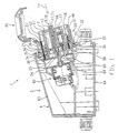
- Fig. 1 shows a longitudinal section of a plug-in device 1 with a socket 3, in the from plug 14, a plug 2, not shown, see FIGS. 2 and 3, can be inserted is.
- the socket 3 has a housing 4 of an upper housing portion 63 and a lower housing portion 64 on. These are bolted together releasably connected.
- a Housing opening 31 is arranged.
- a plug housing 28th releasably secured by means of a peripheral flange 30 at its peripheral edge.
- a lid 82 is pivotally mounted on the connector housing 28, a lid 82 is pivotally mounted.
- a socket insert 7 is arranged, the lower End portion 26 is surrounded by a ring member 27.
- Plug housing 28, ring element 27 and socket insert 7 are with their lower ends 30, 29 and 58, see Also Fig. 3, arranged flush and through the housing opening 31 into the housing 4 inserted.
- There is a switching device 34 within the housing 4 a fixing plate 35 and a switching disc 36 is arranged.
- the two Discs 35, 36 are concentric with each other and have the same radius.
- the fixing plate 35 is by means not shown in Fig. 1 mounting projections 76, see Fig. 10, at the lower end 30 of the plug housing 28 by screwing fixable.
- connector housing 28 and mounting washer 35 are rotationally fixed attached to each other on the housing 4.
- Fastening washer 35 has on its the Socket insert 7 assigning front to a guide wall 56 which is circular runs.
- the guide wall 56 is in a en Maschinenende annular groove 57 at the bottom Inserted end 58 of the socket insert 7 to the rotatable mounting.
- a blocking recess 40 see Fig. 2 and 10, arranged.
- a locking device 8 forming Locking pin 13 can be inserted.
- an end sleeve 23 is arranged, which opens in the direction of blocking recess 40 is.
- This centering pin 25 is arranged centrally, which protrudes from the ferrule 23 and on which a spring 24 is partially attached. The spring 24 is supported on the ground the blocking recess 40 from and force the locking pin 13 in Direction of his in Fig. 1 illustrated release position 10.
- the socket insert 7 is rotatable relative to the switching device 34.
- At least one switching cam 60 is disposed on the switching disk 36.
- the switching disk 36 In the in Fig. 1 represented detent position 37, see also Fig. 10, the switching disc 36 relative to Mounting plate 35, the switching cam 60 presses a pin-shaped switching device 61 in the direction of a break switch 62. This is the electrical connector 1 is switched to a de-energized state by the interruption switch 62, in which a connection between the cable 3 brought up to the socket (not shown) and plugged into the socket 3 plug 2 is interrupted.
- a locking insert 46 is displaced in the longitudinal direction stored. This is in the sectional view of FIG. 1 L-shaped.
- a spring 55 is the Arretierprin 46 in the direction of connector 2, see Fig. 2, subjected to force.
- the socket insert 7 Within the socket insert 7 are three, four or more receiving holes 17th formed in which contact plug sleeves 18 are inserted. These are with cables 66, see Fig. 2, connected to a rear side of the breaker switch 62 and are held by the mounting plate 35, see Figs. 10 and 11.
- the release position 10 of the locking pin 13 is determined by a stop 20, which is formed by an upper end of the ferrule 23, see also Fig. 2.
- the Stop 20 is connected to a lower end 21 of a longitudinal guide 16 in Appendix. In this the locking pin 13 is slidably mounted.
- the locking pin 13 has in particular at its upper end 15 a coding projection 11, which has a certain cross-section.
- This cross section sets in the embodiment of FIG. 1 along the entire locking pin thirteenth up to its lower end 19. Is the locking pin 13 against the force of Spring 24 is inserted into the blocking recess 40 with its lower end 19, so is he arranged in blocking position 9, see also Fig. 3rd
- Fig. 2 is a section through the socket 3 of FIG. 1 with inserted plug. 2 shown.
- Fig. 1 the same Parts provided with the same reference numerals and are only partially mentioned.
- Fig. 2 and the following figures supplementary refer to the description with regard to FIG. 1.
- the plug 2 is constructed in a conventional manner. According to the invention he instructs its front side a Kodierausappelung 12, whose cross section is the cross section of the locking pin 13 corresponds. According to Fig. 2, the end 15, see Fig. 1, of Locking pin 13 inserted in the Kodierausappelung 12. This leaves the Locking pin 13 even when plugged 2 in the release position 10th
- the plug 2 has a sleeve-shaped surrounding the socket insert 7 Stekkerkragen 48, which is inserted between the connector housing 28 and socket insert 7 is.
- a radially outwardly projecting Edge cam 69 arranged at the front end of the plug collar 48. This presses the locking insert 46 in the direction Switching device 34 against the force of the spring 55. This causes a locking projection 50, see for example Figs. 8 and 9, out of engagement with one on an inside of the Plug housing 28 trained guide, whereby the socket insert 7 with Ring element 27 is rotatable relative to the plug housing 28.
- the twist of the Socket insert 7 is made by turning the plug 2, with its Stekkerstatten 65 is inserted into the corresponding contact plug sleeves 18.
- FIG. 3 shows a representation analogous to FIG. 2 with a plug 2 without coding recess 12th
- Fig. 4 is a front view of the socket insert 7 of FIG. 1 to 3 is shown. This is by twisting means of the plug, see for example Fig. 2, between a switch-off 5 and a closed position 6 rotatable.
- the ring member 27 is carried, see the following Embodiments, whereby by means of the driver 41, see also Fig. 2, between the Locking positions 37, 38, see Fig. 10, the switching disc 36 is switched back and forth.
- the longitudinal guide 16 is arranged, which in this embodiment has a three-pronged cross section, wherein the three prongs arranged T-shaped and go out from an approximately circular center.
- the socket insert 7 In the lower end portion 26, see for example Fig. 1, the socket insert 7 a shoulder 83 extending radially outwardly and a plurality of bearing pockets 52, of which in Fig. 4 only one is shown.
- the storage pockets 52 are along arranged the circumference of the socket insert 7.
- a hole 77 is arranged, in which a lower end of the spring 55, see Fig. 1 to 3, is inserted for the locking insert 46.
- the storage pockets 52 form Guide for the Arretierprin 46, see also Fig. 8 and 9.
- the ring member 27 On the paragraph 83 or on upper ends of the bearing pockets 52, the ring member 27 by means of a on the Inside trained paragraph 71, see Fig. 5, rotatably mounted.
- Fig. 5 is a front view of the ring member 27 is shown. This points to his Inside the paragraph 71 on.
- an L-shaped Guide slot 44 is formed in the wall of the ring member 27 in the wall of the ring member 27 in the wall of the ring member 27 .
- the vertical L-leg 47 extends in the longitudinal direction 53, see Fig. 2, of the socket insert 7.
- the vertical L-leg 47 of the locking insert 46 is guided, see FIGS. 8 and 9.
- the locking insert 46th down along the vertical L-leg 47 in the direction of driver 41 and depressed can then along the horizontal L-leg 49 to the edge 51 of the guide slot 44 by rotating the socket insert 7 relative to the ring element 27 be moved.
- the guide slot 44 is from the lower end 29 with ring element 27 of the ring member 27 of the driver 41, wherein between driver 41 and ring element 27 a paragraph 72 is formed. This is located in the plug housing 28 inserted Socket insert 7 at the lower end 30 of the plug housing 28 at.
- Fig. 6 is a front view of the locking pin 13 as a locking device 8 is shown. This is corresponding to the cross section of the longitudinal guide 16, see FIG. 4, formed in a trident, see also Fig. 7.
- the three prongs are T-shaped to each other arranged and extending from an approximately circular center.
- the top End 15 of the locking pin 13 is usually in the direction of plug 2 from the Longitudinal guide 16 of the socket insert 7 before, see also Fig. 1 to 3.
- the lower End 19 is formed with the end sleeve 23, arranged in the center of the centering pin 25 is.
- the end sleeve 23 is arranged in the blocking recess 40, see FIGS. 1 and 2, wherein an upper end of the end sleeve 23 forms a stop 20, see also Fig. Second
- Fig. 7 is a plan view of the locking pin 13 of FIG. 6 is shown. Especially the T-shaped arrangement of the three teeth of the cross section around the circular Center 73 is visible.
- the diameter of the end sleeve 12 is larger than a corresponding one Diameter of the circular center 73, so that by the radial projection of the End sleeve 20 on the nikfömige center 73 of the stop 20 is formed.
- Fig. 8 is a front view of the Arretierprines 46 is shown. This is plate-shaped formed with lateral guide projections 74. At the bottom of the locking insert 46 is the locking projection 50, which has an approximately semicircular Cross-section with radially outwardly projecting nose 84 has. This nose is 84 as part of the locking projection 50 in a corresponding groove on the inside of the Plug housing 28 is arranged until the locking projection 50 in the horizontal L-leg 49, see Fig. 5, of the ring member 27 is shifted. This is one rotationally fixed coupling between socket insert 7 and plug housing 28 given.
- FIG. 9 shows a plan view of the locking insert 46 according to FIG. 8.
- a bore 75 is formed, which to the lower end, see Fig. 8, the Arretierlandaises 46 for receiving the spring 55, see Fig. 1 to 3, open is.
- Fig. 10 is a plan view of the switching device 34 and in particular on the mounting plate 35 shown. This is circular with four radially to the circumference outwardly projecting fastening projections 76 are formed. The fastening projections 76 serve to screw the switching device 34 to the lower end 30 of the plug housing 28, see Fig. 1 to 3.
- the guide wall 56 is disposed in the annular groove 57 at the lower end 58 of the socket insert 7 engages.
- the blocking recess 40 outlined. Its cross section corresponds to the cross section of the locking pin 13. It should be noted that the diameter of the circular Center of the blocking recess 40 corresponds to the diameter of the ferrule 23, since this is mounted displaceably in the circular center, see Fig. 1 to 3.
- the blocking recess 40 is surrounded by four bushings 78, the slot-like run curved around the blocking recess 40. Between the individual executions 78 are arranged webs on which corresponding webs 80, see FIG. 11, a holder 79 are rotatably mounted.
- the bushings 78 open into a circular opening of the switching disc 36 and serve for the passage of cables 66, see Fig. 2, at the ends of the contact plug sleeves 18 are arranged.
- a part-circular slot guide 42 formed, through which the switching disk 36 is visible.
- the latter has a driver intake 43, in which the driver 41, see Fig. 1 to 3, of the ring member 27th is pluggable.
- Fig. 11 is a plan view of the holder 79 is shown. This one is with its webs 80 on the connecting webs between the bushings 78, see Fig. 10, rotatable stored.
- the holder 79 bearing eyes 81 which has a radially outwardly open Having passage slot. Through this are the lower ends of the contact plug sleeves 18 insertable into the bearing eyes 81 and then store these lower ends on top of the bearing eyes.
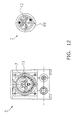
- Figs. 12 to 14 are three different embodiments of connector 2 and Socket 3 with different codes of locking pin 13 and coding projection 11 and coding recess 12 shown.
- Fig. 12 the coding is carried out by a tri-section of the coding projection 11, wherein the three individual prongs each at angles of 120 ° to each other are arranged. Complementary to the Kodieraus Principleung 12 is formed.
- coding is performed by a two-bar coding projection, wherein the enclose an approximate angle of 120 ° in both individual prongs. This applies analogously for the coding recess 12.
- a plug 3 inappropriate plug 2 is inserted, the otherwise appropriate Having pins and the like.
- the locking pin 13 is moved to its blocking position 9. In this position is its lower end 58 is inserted into the blocking recess 40 of the fastening disk 35.
- Blocking recess 40 and locking pin 13 have complementary Cross-sections on a rotationally fixed coupling of mounting plate 35 and socket insert 7 allow.
- the socket insert 7 by depressing the Arretierassies 46th by edge cams 69 of the plug 2 together with ring member 27 relative to the plug housing 28 rotatable.
- the switching cam 60 can not by turning the Switching disc 36 in another detent position out of engagement with the pin-shaped switching device 61 of the interruption switch 62 are brought. Therefore, the Socket insert continues to be de-energized by the breaker switch 62.
- the plug 2 of FIG. 2 shows a Kodieraus Principleung 12 with Coding projection 11 of the locking pin 13 complementary cross section in his Front side.
- the locking pin 13 is also at the socket insert. 7 plugged plug 2 is still arranged in its release position 10.
- the locking pin 13 only with its end sleeve 23 in the blocking recess 40th arranged so that socket insert 7 with ring member 27 relative to the mounting plate 35 for adjusting the switching disc 36 by means of drivers 41 are rotatable.
- the switching cam 60 is also relative to the pin-shaped Switching device 61 twisted, causing them from the breaker switch 62 moves out and the breaker switch the socket insert 7 with voltage provided.
Landscapes
- Details Of Connecting Devices For Male And Female Coupling (AREA)
- Connector Housings Or Holding Contact Members (AREA)
- Optical Couplings Of Light Guides (AREA)
- Insulated Conductors (AREA)
- Coupling Device And Connection With Printed Circuit (AREA)
- Connections Arranged To Contact A Plurality Of Conductors (AREA)
Description
Claims (25)
- Elektrische Steckvorrichtung (1) insbesondere für explosionsgeschützte Bereiche, mit einem Stecker (2) und einer Steckdose (3), welche wenigstens ein Gehäuse (4) und einen in diesen zwischen einer Ausschalt- und einer Einschaltstellung (5, 6) verdrehbar gelagerten Steckdoseneinsatz (7) aufweist, der mittels des in der Steckdose (3) eingesteckten Steckers (5) zwischen seinen Stellungen (5, 6) verdrehbar ist, wobei eine Verriegelungseinrichtung (8) im Steckdoseneinsatz (7) verstellbar zwischen einer Blockier- und einer Freigabestellung (9, 10) gelagert ist und in Freigabestellung (10) der Verriegelungseinrichtung (8) der Steckdoseneinsatz (7) zwischen Aus- und Einschaltstellung (5, 6) verdrehbar ist,
dadurch gekennzeichnet, dass die Verriegelungseinrichtung (8) wenigstens einen Kodiervorsprung (11) aufweist, dass der Stecker eine entsprechende Kodierausnehmung (12) aufweist, und dass beim Einstecken des Steckers (2) in den Steckdoseneinsatz (7) der Kodiervorsprung (11) in die entsprechende Kodierausnehmung eingesteckt wird, so dass die Verriegelungseinrichtung (8) in ihrer Freigabestellung (10) verbleibt. - Elektrische Steckvorrichtung nach Anspruch 1, dadurch gekennzeichnet, daß die Verriegelungseinrichtung (8) als Verriegelungsstift (13) ausgebildet ist, welcher im wesentlichen in Einsteckrichtung (14) des Steckers (2) im Steckdoseneinsatz (7) zwischen Blockier- und Freigabestellung (9, 10) längsverschieblich gelagert ist.
- Elektrische Steckvorrichtung nach Anspruch 2, dadurch gekennzeichnet, daß der Verriegelungsstift (13) in Freigabestellung (10) mit einem seiner Enden (15) als Kodiervorsprung (11) aus dem Steckdoseneinsatz (7) in Richtung Stecker (2) vorsteht.
- Elektrische Steckvorrichtung nach wenigstens einem der vorangegangenen Ansprüche 2 oder 3, dadurch gekennzeichnet, daß der Verriegelungsstift (13) in Richtung Freigabestellung (10) kraftbeaufschlagt ist.
- Elektrische Steckvorrichtung nach wenigstens einem der vorangehenden Ansprüche 2-4, dadurch gekennzeichnet, daß der Verriegelungsstift (13) im wesentlichen mittig im Steckdoseneinsatz (7) angeordnet ist.
- Elektrische Steckvorrichtung nach wenigstens einem der vorangehenden Ansprüche, dadurch gekennzeichnet, daß der Kodiervorsprung (11) im Querschnitt komplementär zum Querschnitt der Kodierausnehmung (12) ausgebildet ist.
- Elektrische Steckvorrichtung nach wenigstens einem der vorangehenden Ansprüche 2-6, dadurch gekennzeichnet, daß der Steckdoseneinsatz (7) eine Längsführung (16) für den Verriegelungsstift (13) aufweist, deren Querschnitt im wesentlichen gleich dem Querschnitt des Kodiervorsprungs (11) ist.
- Elektrische Steckvorrichtung nach Anspruch 7, dadurch gekennzeichnet, daß Aufnahmebohrungen (17) für elektrische Kontaktsteckerhülsen (18) um die Längsführung (16) herum im Steckdoseneinsatz (7) angeordnet sind.
- Elektrische Steckvorrichtung nach wenigstens einem der vorangehenden Ansprüche 7,8, dadurch gekennzeichnet, daß der Verriegelungsstift (13) an seinem dem Stecker (2) gegenüberliegenden, unteren Ende (19) aus der Längsführung (16) vorsteht und einen Anschlag (20) aufweist, der mit einem unteren Ende (21) der Längsführung (16) in Anlage bringbar ist.
- Elektrische Steckvorrichtung nach Anspruch 9, dadurch gekennzeichnet, daß der Anschlag (20) als oberes Ende (22) einer nach unten offenen Endhülse (23) des Verriegelungsstiftes (13) ausgebildet ist, wobei in der Endhülse zumindest teilweise eine Feder (24) zur Kraftbeaufschlagung in Richtung Freigabestellung (10) des Verriegelungsstiftes (13) anordbar ist.
- Elektrische Steckvorrichtung nach wenigstens einem der vorangehenden Ansprüche, dadurch gekennzeichnet, daß ein Zentrierstift (25) mittig in der Endhülse (23) angeordnet ist, auf den die Feder (24) zumindest teilweise aufschiebbar ist.
- Elektrische Steckvorrichtung nach wenigstens einem der vorangehenden Ansprüche, dadurch gekennzeichnet, daß der Steckdoseneinsatz (7) wenigstens in seinem unteren Endabschnitt (26) in einem Ringelement (27) gelagert ist, mit welchem zusammen der Steckdoseneinsatz (7) in ein am Gehäuse (4) lösbar befestigtes Steckergehäuse (28) einsteckbar ist.
- Elektrische Steckvorrichtung nach Anspruch 12, dadurch gekennzeichnet, daß Ringelement (27), Steckdoseneinsatz (7) und Steckergehäuse (28) an ihren jeweils dem Gehäuse (4) zuweisenden unteren Enden (29, 30, 58) bündig zueinander abschließen und teilweise in eine Gehäuseöffnung (31) im Gehäuse (4) hineinragen.
- Elektrische Steckvorrichtung nach wenigstens einem der vorangehenden Ansprüche, dadurch gekennzeichnet, daß das Steckergehäuse (28) einen umlaufenden Randflansch (32) aufweist, der an einer Umrandung (33) der Gehäuseöffnung (31) lösbar befestigbar ist.
- Elektrische Steckvorrichtung nach wenigstens einem der vorangehenden Ansprüche, dadurch gekennzeichnet, daß das Steckergehäuse (28) mit einer die Kontaktsteckerhülsen (18) tragenden, scheibenförmigen Schalteinrichtung (34) innerhalb des Gehäuses (4) verbindbar ist, welche wenigstens eine Befestigungsscheibe (35) und eine Schaltscheibe (36) aufweist, die relativ zueinander verdrehbar in zwei Raststellungen (37, 38) anordbar sind.
- Elektrische Steckvorrichtung nach Anspruch 15, dadurch gekennzeichnet, daß die Befestigungsscheibe (35) auf ihrer dem Steckdoseneinsatz (7) zuweisenden Vorderseite (39) eine Blockierausnehmung (40) aufweist, in die das untere Ende (19) des Verriegelungsstiftes (13) einsteckbar ist, wodurch Steckdoseneinsatz (7) und Befestigungsscheibe (35) drehfest miteinander gekoppelt sind.
- Elektrische Steckvorrichtung nach wenigstens einem der vorangehenden Ansprüche 12-16, dadurch gekennzeichnet, daß das Ringelement (27) einen in Richtung Schalteinrichtung (34) vorstehenden Mitnehmer (41) aufweist, der durch eine Schlitzführung (42) in der Befestigungsscheibe (35) in eine an der Schaltscheibe (36) angeordnete Mitnehmeraufnahme (43) eingreift.
- Elektrische Steckvorrichtung nach wenigstens einem der vorangehenden Ansprüche 12-17, dadurch gekennzeichnet, daß das Ringelement (27) einen im wesentlichen L-förmigen Führungsschlitz (44) für einen am Außenumfang (45) des Steckdoseneinsatzes (7) längsverschieblich gelagerten Arretiereinsatz (46) aufweist, welcher entlang des vertikalen L-Schenkels (47) durch einen Steckerkragen (48) des Steckers (2) beim Einstecken in den Steckdoseneinsatz (7) und anschließend entlang des horizontalen L-Schenkels (49) durch Verdrehen des Steckdoseneinsatzes (7) relativ zum Ringelement (27) bewegbar ist.
- Elektrische Steckvorrichtung nach Anspruch 18, dadurch gekennzeichnet, daß der Arretiereinsatz (46) einen radial nach außen relativ zum Steckdoseneinsatz (7) vorstehenden Arretiervorsprung (50) aufweist, der mit Rändern (51) des Führungsschlitzes (44) in Anlage bringbar ist.
- Elektrische Steckvorrichtung nach wenigstens einem der vorangehenden Ansprüche 18,19, dadurch gekennzeichnet, daß der Arretiereinsatz (46) in wenigstens einer am unteren Endabschnitt (26) des Steckdoseneinsatzes (7) angeordneten Lagertasche (52) in Längsrichtung (53) des Steckdoseneinsatzes (7) verschieblich gelagert ist.
- Elektrische Steckvorrichtung nach Anspruch 20, dadurch gekennzeichnet, daß zwischen Arretiereinsatz (46) und Boden (54) der Lagertasche (52) eine Feder (55) zur Kraftbeaufschlagung des Arretiereinsatzes (46) in Richtung Stecker (2) angeordnet ist.
- Elektrische Steckvorrichtung nach wenigstens einem der vorangehenden Ansprüche 20,21, dadurch gekennzeichnet, daß eine Vielzahl von Lagertaschen (52) entlang des Umfangs des Steckdoseneinsatzes (7) insbesondere nebeneinander angeordnet sind.
- Elektrische Steckvorrichtung nach wenigstens einem der vorangehenden Ansprüche, dadurch gekennzeichnet, daß der Kodiervorsprung (11) einen halbkreis-, teilkreis-, kreisförmigen, zwei-, drei- oder mehrzackigen oder eckigen Querschnitt aufweist.
- Elektrische Steckvorrichtung nach wenigstens einem der vorangehenden Ansprüche 15-23, dadurch gekennzeichnet, daß die Befestigungsscheibe (35) eine in Richtung Steckdoseneinsatz (7) vorstehende Führungswand (56) aufweist, die in eine Ringnut (57) im unteren Ende (58) des Steckdoseneinsatzes (7) zu dessen Drehlagerung eingreift.
- Elektrische Steckvorrichtung nach wenigstens einem der vorangehenden Ansprüche 15-24, dadurch gekennzeichnet, daß die Schaltscheibe (36) auf ihrer der Befestigungsscheibe (35) gegenüberliegenden Rückseite (59) wenigstens einen Schaltnocken (60) aufweist, der bei Verdrehung der Schaltscheibe (36) mittels des Mitnehmers (41) eine Schalteinrichtung (61) eines im Gehäuse (4) angeordneten Unterbrechungsschalters (62) in Verbindungs- oder Unterbrechungsstellung verstellt.
Applications Claiming Priority (3)
| Application Number | Priority Date | Filing Date | Title |
|---|---|---|---|
| DE29915263U | 1999-08-31 | ||
| DE29915263U DE29915263U1 (de) | 1999-08-31 | 1999-08-31 | Elektrische Steckvorrichtung |
| PCT/EP2000/004697 WO2001017070A1 (de) | 1999-08-31 | 2000-05-23 | Elektrische steckvorrichtung |
Publications (2)
| Publication Number | Publication Date |
|---|---|
| EP1208619A1 EP1208619A1 (de) | 2002-05-29 |
| EP1208619B1 true EP1208619B1 (de) | 2005-07-20 |
Family
ID=8078259
Family Applications (1)
| Application Number | Title | Priority Date | Filing Date |
|---|---|---|---|
| EP00935103A Expired - Lifetime EP1208619B1 (de) | 1999-08-31 | 2000-05-23 | Elektrische steckvorrichtung |
Country Status (6)
| Country | Link |
|---|---|
| US (1) | US7537472B1 (de) |
| EP (1) | EP1208619B1 (de) |
| AT (1) | ATE300105T1 (de) |
| DE (2) | DE29915263U1 (de) |
| NO (1) | NO320523B1 (de) |
| WO (1) | WO2001017070A1 (de) |
Cited By (2)
| Publication number | Priority date | Publication date | Assignee | Title |
|---|---|---|---|---|
| CN110797703A (zh) * | 2019-11-20 | 2020-02-14 | 象山罗雅电子科技有限公司 | 一种可变电压和用电形式的插座 |
| US12482993B2 (en) | 2020-01-14 | 2025-11-25 | Eaton Intelligent Power Limited | Electrical socket with switch to prevent electrical arc in explosive environments |
Families Citing this family (22)
| Publication number | Priority date | Publication date | Assignee | Title |
|---|---|---|---|---|
| US6774307B2 (en) * | 2002-05-07 | 2004-08-10 | Applied Technology And Solutions | Through-wall electrical system |
| DE202004010818U1 (de) * | 2004-07-10 | 2005-11-24 | Wiska Hoppmann & Mulsow Gmbh | Vorrichtung zur Betätigung eines in einem Gehäuse angeordneten Leistungsschalters |
| DE102004045455A1 (de) * | 2004-09-20 | 2006-04-06 | BöSha GmbH + Co KG | Explosionsgeschützte elektrische Betriebmittel, insbesondere Leuchten und Verteilerkästen, in überwachten Stromkreisen mit Steckverbindungen |
| US7666010B2 (en) * | 2006-10-27 | 2010-02-23 | Leviton Manufacturing Company, Inc. | Modular wiring system with locking elements |
| US7955096B2 (en) * | 2006-10-27 | 2011-06-07 | Leviton Manufacturing Company, Inc. | Modular wiring system with locking elements |
| DE202008011268U1 (de) * | 2008-08-25 | 2010-02-11 | Wiska Hoppmann & Mulsow Gmbh | Leistungsgeschalteter Steckdosenplatz |
| US20140259651A1 (en) * | 2009-05-04 | 2014-09-18 | Nicholas Fletcher | Socket switch |
| CH702854A1 (de) * | 2010-03-18 | 2011-09-30 | Huber+Suhner Ag | Interfaceverbinder. |
| JP5602642B2 (ja) * | 2011-01-04 | 2014-10-08 | 富士通コンポーネント株式会社 | コネクタ |
| US8371863B1 (en) | 2011-07-29 | 2013-02-12 | Leviton Manufacturing Company, Inc. | Modular wiring system |
| US8678867B2 (en) | 2011-10-31 | 2014-03-25 | Lear Corporation | Electrical terminal and receptacle assembly |
| US8414339B1 (en) | 2011-10-31 | 2013-04-09 | Lear Corporation | Electrical terminal and receptacle assembly |
| US9236682B2 (en) | 2013-02-15 | 2016-01-12 | Lear Corporation | Cylindrical electric connector with biased contact |
| USD765599S1 (en) * | 2013-07-17 | 2016-09-06 | Cooper Crouse-Hinds Gmbh | Socket |
| PL4088595T3 (pl) * | 2014-09-17 | 2024-04-22 | Fontem Ventures B.V. | Urządzenie do przechowywania i odparowywania substancji ciekłych |
| US9472908B2 (en) | 2014-11-29 | 2016-10-18 | Appleton Grp, Llc | Electrical plug and receptacle assembly with interlock mechanism |
| EP3325306B1 (de) * | 2015-07-22 | 2024-10-02 | Appleton Grp LLC | Masseanschlussleiste mit mehreren positionen für steckdosen |
| FR3051607A1 (fr) * | 2016-05-19 | 2017-11-24 | Afield Sustainable Innovations Sas | Connecteur electrique securise |
| DE102018105510A1 (de) | 2018-03-09 | 2019-09-12 | Eaton Protection Systems Ip Gmbh & Co. Kg | Elektrische Steckvorrichtung |
| DE102018105486A1 (de) | 2018-03-09 | 2019-09-12 | Eaton Protection Systems Ip Gmbh & Co. Kg | Elektrische steckvorrichtung |
| CN117913943B (zh) * | 2024-01-05 | 2024-06-14 | 浙江天能电池(江苏)有限公司 | 一种锂电池电压监测装置 |
| CN119231258B (zh) * | 2024-09-30 | 2025-11-04 | 中国煤炭科工集团太原研究院有限公司 | 一种矿用电动车防爆型开关装置 |
Family Cites Families (32)
| Publication number | Priority date | Publication date | Assignee | Title |
|---|---|---|---|---|
| DE558669C (de) | 1929-07-10 | 1932-09-09 | Dietz & Ritter G M B H | Steckvorrichtung mit in die Steckdose eingebautem Drehschalter |
| CH311948A (de) | 1952-12-23 | 1955-12-15 | Ginggen Alfred | Steckdose mit Stecker. |
| CH323136A (it) | 1953-07-03 | 1957-07-15 | Rizzieri Italo | Dispositivo di collegamento elettrico ad innesto |
| US3023394A (en) | 1958-03-17 | 1962-02-27 | Hubbell Inc Harvey | Multi-wire connector and plug with selective central key means for different voltages |
| US3525068A (en) * | 1968-07-01 | 1970-08-18 | Electro Oceanics Inc | Fluid proof connector with insulated contacts |
| AT313404B (de) * | 1970-03-31 | 1974-02-25 | Staff & Schwarz Gmbh | Elektrische Kupplung zum Verbinden elektrischer Leitungen |
| US3853376A (en) | 1972-03-30 | 1974-12-10 | G Marechal | Electric connection devices |
| US3789346A (en) | 1972-09-05 | 1974-01-29 | West Virginia Armature Co | Electrical coupling with pressure contacts and multiple conductance paths |
| US3808579A (en) | 1972-11-06 | 1974-04-30 | Akzona Inc | Explosion proof connector |
| FR2266332A1 (en) | 1974-03-26 | 1975-10-24 | Souriau & Cie | Multiway electrical plug and socket connector - has make and break pin circuit indicating correct connection |
| DE2433729A1 (de) * | 1974-07-13 | 1976-02-05 | Multicontact Ag | Steckvorrichtung |
| US4198110A (en) | 1978-06-08 | 1980-04-15 | General Energy Development Corp. | Connector |
| US4193655A (en) * | 1978-07-20 | 1980-03-18 | Amp Incorporated | Field repairable connector assembly |
| DE2832105A1 (de) * | 1978-07-21 | 1980-01-31 | Playsafe Electrics | Elektrische stecker-steckdosen-anordnung |
| DE3220839C2 (de) * | 1982-06-03 | 1985-04-18 | Brown, Boveri & Cie Ag, 6800 Mannheim | Explosions- oder schlagwettergeschützte Steckvorrichtung |
| DE3411170A1 (de) * | 1984-03-27 | 1985-10-03 | R. Stahl Schaltgeräte GmbH, 7118 Künzelsau | Explosionsgeschuetzter steckverbinder mit drehbarem buchsentraeger |
| DE3413777A1 (de) * | 1984-04-12 | 1985-11-21 | Brown, Boveri & Cie Ag, 6800 Mannheim | Explosions- oder schlagwettergeschuetzte kupplungssteckvorrichtung |
| US4772215A (en) * | 1987-10-15 | 1988-09-20 | Hubbell Incorporated | Electrical connector with enclosed internal switch |
| US5386486A (en) * | 1991-11-07 | 1995-01-31 | Litecom, Inc. | Connecting system for field installation and cleaning |
| US5423692A (en) | 1993-11-05 | 1995-06-13 | Litton Systems, Inc. | Power connector set |
| US5417594A (en) | 1994-03-07 | 1995-05-23 | Hubbell Incorporated | Male electrical plug assembly with increased electrical creepage distance between contacts |
| GB2292644B (en) * | 1994-08-16 | 1997-03-26 | Caradon Mk Electric Ltd | Improvements in and relating to electrical switch sockets |
| FR2727799B1 (fr) | 1994-12-02 | 1997-01-17 | Marechal Sepm | Prise pour connexion electrique, a contacts proteges |
| FR2734668B1 (fr) | 1995-05-24 | 1997-08-01 | Legrand Sa | Socle de prise de courant a interrupteur incorpore |
| US6162082A (en) | 1999-01-28 | 2000-12-19 | Badger Meter, Inc. | Submersible electrical connector and method for quick connection and disconnection including tamper indication |
| US6206714B1 (en) | 1999-02-01 | 2001-03-27 | Litton Systems, Inc. | Plug and adapter for existing single pole electrical receptacle |
| DE19916075C1 (de) | 1999-04-09 | 2001-02-08 | Framatome Connectors Int | Elektrische Steckverbindung, insbesondere für Kfz-Anwendungen |
| US7066758B2 (en) * | 1999-08-31 | 2006-06-27 | Cooper Crouse-Hinds Gmbh | Electrical socket |
| US6382990B1 (en) | 1999-11-19 | 2002-05-07 | Societe D'exploitation Des Procedes Marechal (Sepm) | Electric connection base plate in particular for explosible environment and method for making same |
| US6764351B2 (en) * | 2001-08-27 | 2004-07-20 | Campagnie Deutsch GmbH | Electrical connector |
| US6551136B2 (en) * | 2001-09-20 | 2003-04-22 | Adc Telecommunications, Inc. | Closed end coaxial connector |
| US7316584B2 (en) * | 2005-09-13 | 2008-01-08 | Deutsch Engineered Connecting Devices, Inc. | Matched impedance shielded pair interconnection system for high reliability applications |
-
1999
- 1999-08-31 DE DE29915263U patent/DE29915263U1/de not_active Expired - Lifetime
-
2000
- 2000-05-23 WO PCT/EP2000/004697 patent/WO2001017070A1/de not_active Ceased
- 2000-05-23 EP EP00935103A patent/EP1208619B1/de not_active Expired - Lifetime
- 2000-05-23 DE DE50010764T patent/DE50010764D1/de not_active Expired - Lifetime
- 2000-05-23 AT AT00935103T patent/ATE300105T1/de not_active IP Right Cessation
- 2000-05-23 US US10/069,760 patent/US7537472B1/en not_active Expired - Fee Related
-
2002
- 2002-02-27 NO NO20020956A patent/NO320523B1/no not_active IP Right Cessation
Cited By (2)
| Publication number | Priority date | Publication date | Assignee | Title |
|---|---|---|---|---|
| CN110797703A (zh) * | 2019-11-20 | 2020-02-14 | 象山罗雅电子科技有限公司 | 一种可变电压和用电形式的插座 |
| US12482993B2 (en) | 2020-01-14 | 2025-11-25 | Eaton Intelligent Power Limited | Electrical socket with switch to prevent electrical arc in explosive environments |
Also Published As
| Publication number | Publication date |
|---|---|
| NO320523B1 (no) | 2005-12-12 |
| ATE300105T1 (de) | 2005-08-15 |
| EP1208619A1 (de) | 2002-05-29 |
| WO2001017070A1 (de) | 2001-03-08 |
| NO20020956D0 (no) | 2002-02-27 |
| US7537472B1 (en) | 2009-05-26 |
| DE50010764D1 (de) | 2005-08-25 |
| NO20020956L (no) | 2002-04-24 |
| DE29915263U1 (de) | 2001-01-18 |
Similar Documents
| Publication | Publication Date | Title |
|---|---|---|
| WO2001017070A1 (de) | Elektrische steckvorrichtung | |
| EP1851830B1 (de) | Verbindungssystem, insbesondere elektrisches verbindungssystem | |
| DE10224757B3 (de) | Steckverbinder mit während des Steckvorgangs verrastender Sekundärverriegelung | |
| EP3671979B1 (de) | Reiseadapter sowie set umfassend einen reiseadapter | |
| DE68920712T2 (de) | Elektrischer Kontakt nicht unter Last trennbar, insbesondere für gekuppelte Apparate oder Fahrzeuge. | |
| DE112012004155T5 (de) | Stromanschluss-Verbinder und System | |
| EP1096605A1 (de) | Kabelanschluss- oder -verbindungseinrichtung | |
| EP3787128B1 (de) | Steckverbindung | |
| EP3176885A1 (de) | Steckverbinder und steckerverbinderanordnung | |
| DE29615005U1 (de) | Elektromechanische Verbindungsvorrichtung | |
| DE69504282T2 (de) | Steckdose für eine elektrische Verbindung mit geschützten Kontakten | |
| DE102019000410B4 (de) | Leuchte und Adapter für Leuchte | |
| DE3705413C2 (de) | ||
| EP0444478A1 (de) | Kontaktträger für eine Steckdose oder einen Stecker für eine Steckverbindungen fÀ¼r den elektrischen Anschluss von Kraftfahrzeuganhängern | |
| DE102019114262B3 (de) | Steckverbinder mit Verriegelungssystem | |
| DE4126923C1 (de) | ||
| DE102018105486A1 (de) | Elektrische steckvorrichtung | |
| EP1756919B1 (de) | Elektrischer kupplungs-adapter und steckdose | |
| EP1035619B1 (de) | Stecker | |
| DE19615373C2 (de) | Fassung, insbesondere für stabförmige Leuchtstoffröhren | |
| DE10346367B4 (de) | Freidrehbarer HF-Winkelsteckverbinder | |
| DE8424990U1 (de) | Näherungsschalter | |
| EP0438630A1 (de) | Explosionsgeschützte Lampenfassung | |
| WO2002097928A1 (de) | Kabelverbindungsvorrichtung | |
| DE102004062414A1 (de) | Lampenfassung |
Legal Events
| Date | Code | Title | Description |
|---|---|---|---|
| PUAI | Public reference made under article 153(3) epc to a published international application that has entered the european phase |
Free format text: ORIGINAL CODE: 0009012 |
|
| 17P | Request for examination filed |
Effective date: 20020124 |
|
| AK | Designated contracting states |
Kind code of ref document: A1 Designated state(s): AT BE CH CY DE DK ES FI FR GB GR IE IT LI LU MC NL PT SE |
|
| RAP1 | Party data changed (applicant data changed or rights of an application transferred) |
Owner name: COOPER CROUSE-HINDS GMBH |
|
| GRAP | Despatch of communication of intention to grant a patent |
Free format text: ORIGINAL CODE: EPIDOSNIGR1 |
|
| GRAS | Grant fee paid |
Free format text: ORIGINAL CODE: EPIDOSNIGR3 |
|
| GRAA | (expected) grant |
Free format text: ORIGINAL CODE: 0009210 |
|
| AK | Designated contracting states |
Kind code of ref document: B1 Designated state(s): AT BE CH CY DE DK ES FI FR GB GR IE IT LI LU MC NL PT SE |
|
| PG25 | Lapsed in a contracting state [announced via postgrant information from national office to epo] |
Ref country code: IE Free format text: LAPSE BECAUSE OF FAILURE TO SUBMIT A TRANSLATION OF THE DESCRIPTION OR TO PAY THE FEE WITHIN THE PRESCRIBED TIME-LIMIT Effective date: 20050720 Ref country code: FI Free format text: LAPSE BECAUSE OF FAILURE TO SUBMIT A TRANSLATION OF THE DESCRIPTION OR TO PAY THE FEE WITHIN THE PRESCRIBED TIME-LIMIT Effective date: 20050720 |
|
| REG | Reference to a national code |
Ref country code: GB Ref legal event code: FG4D Free format text: NOT ENGLISH |
|
| REG | Reference to a national code |
Ref country code: CH Ref legal event code: EP Ref country code: CH Ref legal event code: NV Representative=s name: JACOBACCI & PARTNERS S.P.A. |
|
| GBT | Gb: translation of ep patent filed (gb section 77(6)(a)/1977) |
Effective date: 20050720 |
|
| REG | Reference to a national code |
Ref country code: IE Ref legal event code: FG4D Free format text: LANGUAGE OF EP DOCUMENT: GERMAN |
|
| REF | Corresponds to: |
Ref document number: 50010764 Country of ref document: DE Date of ref document: 20050825 Kind code of ref document: P |
|
| REG | Reference to a national code |
Ref country code: SE Ref legal event code: TRGR |
|
| PG25 | Lapsed in a contracting state [announced via postgrant information from national office to epo] |
Ref country code: GR Free format text: LAPSE BECAUSE OF FAILURE TO SUBMIT A TRANSLATION OF THE DESCRIPTION OR TO PAY THE FEE WITHIN THE PRESCRIBED TIME-LIMIT Effective date: 20051020 Ref country code: DK Free format text: LAPSE BECAUSE OF FAILURE TO SUBMIT A TRANSLATION OF THE DESCRIPTION OR TO PAY THE FEE WITHIN THE PRESCRIBED TIME-LIMIT Effective date: 20051020 |
|
| PG25 | Lapsed in a contracting state [announced via postgrant information from national office to epo] |
Ref country code: ES Free format text: LAPSE BECAUSE OF FAILURE TO SUBMIT A TRANSLATION OF THE DESCRIPTION OR TO PAY THE FEE WITHIN THE PRESCRIBED TIME-LIMIT Effective date: 20051031 |
|
| PG25 | Lapsed in a contracting state [announced via postgrant information from national office to epo] |
Ref country code: PT Free format text: LAPSE BECAUSE OF FAILURE TO SUBMIT A TRANSLATION OF THE DESCRIPTION OR TO PAY THE FEE WITHIN THE PRESCRIBED TIME-LIMIT Effective date: 20051221 |
|
| REG | Reference to a national code |
Ref country code: IE Ref legal event code: FD4D |
|
| ET | Fr: translation filed | ||
| PLBE | No opposition filed within time limit |
Free format text: ORIGINAL CODE: 0009261 |
|
| STAA | Information on the status of an ep patent application or granted ep patent |
Free format text: STATUS: NO OPPOSITION FILED WITHIN TIME LIMIT |
|
| PG25 | Lapsed in a contracting state [announced via postgrant information from national office to epo] |
Ref country code: MC Free format text: LAPSE BECAUSE OF NON-PAYMENT OF DUE FEES Effective date: 20060531 |
|
| 26N | No opposition filed |
Effective date: 20060421 |
|
| PGFP | Annual fee paid to national office [announced via postgrant information from national office to epo] |
Ref country code: CH Payment date: 20080425 Year of fee payment: 9 Ref country code: LU Payment date: 20080508 Year of fee payment: 9 |
|
| PGFP | Annual fee paid to national office [announced via postgrant information from national office to epo] |
Ref country code: AT Payment date: 20080407 Year of fee payment: 9 |
|
| PGFP | Annual fee paid to national office [announced via postgrant information from national office to epo] |
Ref country code: BE Payment date: 20080606 Year of fee payment: 9 |
|
| PGFP | Annual fee paid to national office [announced via postgrant information from national office to epo] |
Ref country code: SE Payment date: 20080505 Year of fee payment: 9 |
|
| PG25 | Lapsed in a contracting state [announced via postgrant information from national office to epo] |
Ref country code: CY Free format text: LAPSE BECAUSE OF FAILURE TO SUBMIT A TRANSLATION OF THE DESCRIPTION OR TO PAY THE FEE WITHIN THE PRESCRIBED TIME-LIMIT Effective date: 20050720 |
|
| BERE | Be: lapsed |
Owner name: *COOPER CROUSE-HINDS G.M.B.H. Effective date: 20090531 |
|
| REG | Reference to a national code |
Ref country code: CH Ref legal event code: PL |
|
| PG25 | Lapsed in a contracting state [announced via postgrant information from national office to epo] |
Ref country code: CH Free format text: LAPSE BECAUSE OF NON-PAYMENT OF DUE FEES Effective date: 20090531 Ref country code: AT Free format text: LAPSE BECAUSE OF NON-PAYMENT OF DUE FEES Effective date: 20090523 Ref country code: LI Free format text: LAPSE BECAUSE OF NON-PAYMENT OF DUE FEES Effective date: 20090531 |
|
| PG25 | Lapsed in a contracting state [announced via postgrant information from national office to epo] |
Ref country code: BE Free format text: LAPSE BECAUSE OF NON-PAYMENT OF DUE FEES Effective date: 20090531 |
|
| PG25 | Lapsed in a contracting state [announced via postgrant information from national office to epo] |
Ref country code: LU Free format text: LAPSE BECAUSE OF NON-PAYMENT OF DUE FEES Effective date: 20090523 |
|
| PG25 | Lapsed in a contracting state [announced via postgrant information from national office to epo] |
Ref country code: SE Free format text: LAPSE BECAUSE OF NON-PAYMENT OF DUE FEES Effective date: 20090524 |
|
| REG | Reference to a national code |
Ref country code: FR Ref legal event code: PLFP Year of fee payment: 17 |
|
| REG | Reference to a national code |
Ref country code: DE Ref legal event code: R082 Country of ref document: DE Ref document number: 50010764 Representative=s name: GRUENECKER PATENT- UND RECHTSANWAELTE PARTG MB, DE Ref country code: DE Ref legal event code: R081 Ref document number: 50010764 Country of ref document: DE Owner name: EATON INTELLIGENT POWER LIMITED, IE Free format text: FORMER OWNER: COOPER CROUSE-HINDS GMBH, 59494 SOEST, DE Ref country code: DE Ref legal event code: R081 Ref document number: 50010764 Country of ref document: DE Owner name: EATON PROTECTION SYSTEMS IP GMBH & CO. KG, DE Free format text: FORMER OWNER: COOPER CROUSE-HINDS GMBH, 59494 SOEST, DE |
|
| REG | Reference to a national code |
Ref country code: FR Ref legal event code: PLFP Year of fee payment: 18 |
|
| REG | Reference to a national code |
Ref country code: FR Ref legal event code: PLFP Year of fee payment: 19 |
|
| REG | Reference to a national code |
Ref country code: DE Ref legal event code: R082 Ref document number: 50010764 Country of ref document: DE Representative=s name: GRUENECKER PATENT- UND RECHTSANWAELTE PARTG MB, DE Ref country code: DE Ref legal event code: R081 Ref document number: 50010764 Country of ref document: DE Owner name: EATON INTELLIGENT POWER LIMITED, IE Free format text: FORMER OWNER: EATON PROTECTION SYSTEMS IP GMBH & CO. KG, 12529 SCHOENEFELD, DE |
|
| PGFP | Annual fee paid to national office [announced via postgrant information from national office to epo] |
Ref country code: NL Payment date: 20190426 Year of fee payment: 20 |
|
| PGFP | Annual fee paid to national office [announced via postgrant information from national office to epo] |
Ref country code: DE Payment date: 20190418 Year of fee payment: 20 Ref country code: IT Payment date: 20190418 Year of fee payment: 20 |
|
| PGFP | Annual fee paid to national office [announced via postgrant information from national office to epo] |
Ref country code: FR Payment date: 20190419 Year of fee payment: 20 |
|
| REG | Reference to a national code |
Ref country code: DE Ref legal event code: R082 Ref document number: 50010764 Country of ref document: DE |
|
| PGFP | Annual fee paid to national office [announced via postgrant information from national office to epo] |
Ref country code: GB Payment date: 20190423 Year of fee payment: 20 |
|
| REG | Reference to a national code |
Ref country code: DE Ref legal event code: R071 Ref document number: 50010764 Country of ref document: DE |
|
| REG | Reference to a national code |
Ref country code: NL Ref legal event code: MK Effective date: 20200522 |
|
| REG | Reference to a national code |
Ref country code: GB Ref legal event code: PE20 Expiry date: 20200522 |
|
| PG25 | Lapsed in a contracting state [announced via postgrant information from national office to epo] |
Ref country code: GB Free format text: LAPSE BECAUSE OF EXPIRATION OF PROTECTION Effective date: 20200522 |