EP1207220B1 - Verfahren zur Oberflächenbehandlung von Aluminium und Aluminiumlegierung - Google Patents
Verfahren zur Oberflächenbehandlung von Aluminium und Aluminiumlegierung Download PDFInfo
- Publication number
- EP1207220B1 EP1207220B1 EP01125530A EP01125530A EP1207220B1 EP 1207220 B1 EP1207220 B1 EP 1207220B1 EP 01125530 A EP01125530 A EP 01125530A EP 01125530 A EP01125530 A EP 01125530A EP 1207220 B1 EP1207220 B1 EP 1207220B1
- Authority
- EP
- European Patent Office
- Prior art keywords
- base material
- aluminum
- silver
- layer
- anodized layer
- Prior art date
- Legal status (The legal status is an assumption and is not a legal conclusion. Google has not performed a legal analysis and makes no representation as to the accuracy of the status listed.)
- Expired - Lifetime
Links
Images


Classifications
-
- C—CHEMISTRY; METALLURGY
- C25—ELECTROLYTIC OR ELECTROPHORETIC PROCESSES; APPARATUS THEREFOR
- C25D—PROCESSES FOR THE ELECTROLYTIC OR ELECTROPHORETIC PRODUCTION OF COATINGS; ELECTROFORMING; APPARATUS THEREFOR
- C25D11/00—Electrolytic coating by surface reaction, i.e. forming conversion layers
- C25D11/02—Anodisation
- C25D11/04—Anodisation of aluminium or alloys based thereon
- C25D11/18—After-treatment, e.g. pore-sealing
- C25D11/20—Electrolytic after-treatment
- C25D11/22—Electrolytic after-treatment for colouring layers
-
- C—CHEMISTRY; METALLURGY
- C25—ELECTROLYTIC OR ELECTROPHORETIC PROCESSES; APPARATUS THEREFOR
- C25D—PROCESSES FOR THE ELECTROLYTIC OR ELECTROPHORETIC PRODUCTION OF COATINGS; ELECTROFORMING; APPARATUS THEREFOR
- C25D11/00—Electrolytic coating by surface reaction, i.e. forming conversion layers
- C25D11/02—Anodisation
- C25D11/024—Anodisation under pulsed or modulated current or potential
-
- C—CHEMISTRY; METALLURGY
- C25—ELECTROLYTIC OR ELECTROPHORETIC PROCESSES; APPARATUS THEREFOR
- C25D—PROCESSES FOR THE ELECTROLYTIC OR ELECTROPHORETIC PRODUCTION OF COATINGS; ELECTROFORMING; APPARATUS THEREFOR
- C25D11/00—Electrolytic coating by surface reaction, i.e. forming conversion layers
- C25D11/02—Anodisation
- C25D11/04—Anodisation of aluminium or alloys based thereon
- C25D11/06—Anodisation of aluminium or alloys based thereon characterised by the electrolytes used
Definitions
- the present invention relates to a surface treating method of surface treating aluminum or aluminum alloy.
- a method of surface treating aluminum or aluminum alloy comprising the steps of anodizing the surface of a base material made from aluminum or aluminum alloy to develop an anodized layer and then applying an alternating current voltage to the base material coated with the anodized layer and immersed in an electrolyte including metallic salts to separate and deposit bits of metal over the anodized layer.
- This method is primarily intended to have the surface of the base material tinted in a desired color.
- Another method of surface treating aluminum or aluminum alloy comprising the steps of anodizing the surface of a base material made from aluminum or aluminum alloy to develop an anodized layer, immersing the base material coated with the anodize layer in a dispersion liquid which contains semiconductor particles for photo-catalysis action, and carrying out an electrophoretic action to fill pores in the anodized layer of the base material with the semiconductor particles.
- This method is generally intended to have the surface of the base material improved in the resistance to microbial attack and pollution.
- an anti-microbial metal such as silver or copper as well as the semiconductor particles. This will improve the anti-microbial property of the base material.
- each of the known surface treating methods allows the deposition of metal to be implemented by electrolytic process (or the filling with semiconductor particles by electrophoresis) only after the anodized layer is developed on the surface of the base material.
- the process for surface treating the base material is carried out by necessarily two to three steps, it will take a considerable length of time and its fabricating system will be bulky and intricate. As a result, the cost of the surface treatment will be increased.
- the base material made of aluminum or aluminum alloy is commonly coated with a fluorine resin for use as e.g. an inner pot of a rice cooker or a hot plate. Since the fluorine resin layer is relatively low in the thermal conductivity, its based kitchenware may suffer from a low level of the heatup efficiency. It is hence desired to improve the efficiency of heatup (for cooking). It is further desired to have the base material improved in the resistance to microbial attack.
- US-A-4,115,211 discloses a bath containing sulfuric acid and copper sulfate for the electrolyzation of an aluminum plate with superimposed AC/DC current.
- the bath containing sulfuric acid and copper sulfate is used for treating the base material as a preprocess of coating in order to prevent the coated layer from peeling off.
- the bath contains soluble metallic salts of zinc, antimony, cadmium, chromium, cobalt, tin, iron, copper, lead, nickel, bismuth, manganese, and molybdenum, but it makes no mention of the bath containing silver nitrate or silver sulfate for the purpose of separating silver that has properties such as anti-microbial property and deodorant property.
- US-A-5,132,003 discloses the anodization of the surface of an aluminum substrate, and the deposition of metal, i.e. copper and silver in the anodized layer by immersing the aluminum substrate that has the anodized layer in the electrolyte. Also it discloses using a sulfate acid as a bath.
- the processes disclosed therein contains two steps, which are the first step of developing an anodized layer (anodic oxidation coating) on the surface of the aluminum substrate, and the second step of depositing metal (i.e. silver) in the anodized layer.
- the process uses two baths, which are the first bath for developing the anodized layer and the second bath for depositing metal. Accordingly, the process is complicated and it takes a considerable length of time and its fabricating system is bulky and intricate.
- US-A-4,230,758 discloses the anodization of the surface of an aluminum substrate, and having the fluorine layer near the anodized layer. However, it does not disclose that the treatment of the aluminum substrate consists of treating the fluorine layer in the electrolytic process.
- US-A-3,929,593 discloses a method of forming a colored oxide film on an aluminum or aluminum alloy material by electrolyzing the aluminum or aluminum alloy material used as one or each of the electrodes in an electrolytic bath containing a metallic salt while applying a pulse voltage consisting of a plurality of unipotential pulses whose polarity is reversed at every predetermined conduction time.
- the aluminum or aluminum alloy material may also be one that has an oxide film previously formed thereon.
- a process for the manufacture of a support for a lithographic printing plate precursor, the process comprising treating at least one surface of a metallic substrate with an aqueous solution comprising a salt of a metal from Group IB, IIB, IVA, IVB, VB, VIA, VIB, VIIB or VIII of the Periodic Table whilst applying a constant voltage or constant current.
- Methods are also disclosed for the manufacture of lithographic printing plate precursors which provide plates showing good resistance to abrasion, corrosion, staining and scumming, both on development and on press. Additionally, the plates display excellent coating adhesion in image areas, together with very good exposure latitude and solvent resistance.
- US-A-3,892,636 discloses an aluminum or aluminum alloy coated with a colored oxide film, produced by applying a direct current which changes polarity at a given frequency alternately, to each of two electrodes, one of which is aluminum or aluminum alloy or both of with are aluminum or aluminum alloy, in an electrolytic bath containing a metal salt to form a colored oxide film on one of the electrodes or both of the electrodes.
- a method of surface treating aluminum or aluminum alloy comprising the steps as set forth in claim 1.
- This method employs the electrolyte which consists mainly of a sulfuric acid bath, an oxalic acid bath, or a mixture thereof with either silver nitrate, or silver sulfate, added and allows the base material immersed in the electrolyte to be fed with an AC/DC combined current, so as to develop an anodized layer on the surface of the base material and simultaneously deposit in the anodized layer silver separated from either the silver nitrate or the silver sulfate. Accordingly, both the development of the anodized layer and the deposition of silver can be implemented by a single action of the electrolytic process.
- This surface treating method can hence simplify and shorten the electrolytic process. Also, the cost for surface treating the base material can be minimized.
- the base material processed by the surface treating method is protected with silver deposited in the pores of its anodized layer, its anti-microbial property, deodorant property, thermal conductivity, and electrical conductivity can successfully be improved while it is tinted in a favorable color. Also, as its anodized layer is reinforced, the base material can have an adequate resistance to wear and a higher level of hardness. This allows the base material to be used as a structural member or a traffic or transportation apparatus component.
- This method allows the base material of aluminum or aluminum alloy to be first coated with at least partially, partially or entirely, a fluorine resin and then subjected to the electrolytic process. While the base material is immersed in the electrolyte it is fed with an AC/DC combined current. This electrolytic action allows the base material to be exposed to the electrolyte through tiny voids provided in the granular resin material and thus have an anodized layer developed on the surface thereof and simultaneously silver separated from the silver nitrate or silver sulfate.
- the base material processed by the surface treating method is protected with silver deposited on its anodized layer, its anti-microbial property, deodorant property, thermal conductivity, and electrical conductivity can successfully be improved.
- a characteristic example of the granular resin is a fluorine resin layer.
- the fluorine resin layer may be applied on one side of the base material which is then subjected to the electrolytic process. This allows the base material to be exposed to the electrolyte through the fluorine resin layer and thus have an anodized layer developed on one side thereof and simultaneously silver from the silver nitrate or the silver sulfate deposited in the anodized layer. Also, the anodized layer is developed on the other side of the base material and bound with the silver separated from the silver nitrate or the silver sulfate.
- the base material can successfully be improved in the anti-microbial property, the deodorant property, the thermal conductivity, and the electrical conductivity.
- the base material may be a pan (e.g. a cooker pan or frying pan), a pot (e.g. an inner pot of a rice cooker), a hot plate, and any other tableware coated at one side with a fluorine resin layer
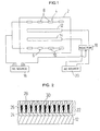
- FIG. 1 is a schematic view of a surface treating apparatus employed for carrying out the surface treating method of the present invention.
- Fig. 2 is a partially enlarged cross sectional view generally showing a base material processed by the surface treating apparatus shown in Fig. 1.
- the treating apparatus includes an electrolytic tub 2 of a rectangular parallelepiped shape in which electrodes 4 and 6 are provided at both sides.
- Each of the electrodes 4 and 6 has four electrode plates 8 or 10 made of a carbon material and connected at equal intervals along the lengthwise direction or the left-to-right direction in Fig. 1.
- the electrodes 4 and 6 are arranged electrically parallel to each other.
- the four electrode plates 8 of the electrode 4 are connected electrically in series and equally the four electrode plates 10 of the electrode 6 are connected in series.
- a pair of base materials 12 and 14 to be surface treated are disposed between the two electrodes 4 and 6. More specifically, the base material 12 is arranged opposite to and inwardly of the electrode 4 while the base material 14 is arranged opposite to and inwardly of the electrode 6.
- the base materials 12 and 14 may be made of a plate-like material, namely aluminum or aluminum alloy of a plate shape. In the treating apparatus having the foregoing arrangement, the base materials 12 and 14 of aluminum or aluminum alloy can be surface treated as will be described later in more detail.
- the electrolytic tub 2 is filled with an electrolyte for surface treating where the base materials 12 and 14 to be treated are immersed.
- the electrolyte may be a sulfuric acid bath, an oxalic acid bath, or their mixture bath.
- the bath is added with silver nitrate.
- the sulfuric acid bath contains, for example, 150 to 300 grams/liter of sulfuric acid.
- the oxalic axis bath contains, for example, 20 to 40 grams/liter of oxalic acid.
- a dope of silver nitrate to be added to the bath may be 2 t 10 grams/liter. If the silver nitrate is less than 2 grams/liter, the amount of separated silver during the surface treating will be declined. If the silver nitrate exceeds 10 grams/liter, the anodized layer may produce more pits (due to porous corrosion) hence resulting in a defective finish.
- the silver nitrate may be replaced by silver sulfate.
- a dose of sliver sulfate to be added is preferably 2 to 10 grams/liter.
- the base materials 12 and 14 are loaded with a current having an AC/DC combined waveform.
- the positive port of a DC source 16 is electrically connected to a reactor 18 while the negative port is electrically connected to the two electrodes 4 and 6(the electrode plates 8 and 10 of).
- the reactor 18 is also electrically connected to an AC source 20.
- the reactor 18 combines the positive DC current from the DC source 16 with the AC current from the AC source 20 to produce a combined current which is supplied to the base materials 12 and 14.
- the current for surface treating is set to such a level that its density ranges from 1 to 10 A/dm 2 .
- the current at a desired density level in the range is continuously supplied for a predetermined length of time. If the current density exceeds 10 A/dm 2 , the anodized layer developed by the surface treating may suffer from color change and burnout or physical injury due to discharge at the interface between the base material 12 or 14 and its holder. When the current density is smaller than 1 A/dm 2 , a flow of the current through the electrolyte will be declined thus decreasing the efficiency of the surface treating.
- the electrolyte during the surface treating may be maintained at a temperature ranging from -10 to 25 °C. If the temperature exceeds 25 °C, the anodized layers developed on the base materials 12 and 14 become softened and will be declined in the surface flatness. When the temperature of the electrolyte is smaller than -10 °C, the efficiency of the surface treating will be declined thus increasing the overall cost.
- Fig. 2 illustrates a finished surface of the base material 12 (14) surface treated by the surface treating apparatus of this embodiment.
- an anodized layer 22 (an anodized aluminum layer) is developed on the base material 12 (14) of aluminum or aluminum alloy.
- the anodized layer 22 consists mainly of a barrier layer 24 deposited on the surface of the base material 12 (14) and a porous layer 26 deposited on the surface of the barrier layer 24.
- the thickness of the barrier layer 24 is substantially 0.01 to 0.1 micrometer while the thickness of the porous layer 26 is substantially 10 to 200 micrometers.
- bits of metal are separated from the metal nitrate and deposited in a multiplicity of pores 28 of the porous layer 26, more particularly silver from silver nitrate (or silver sulfate).
- the base material 12 (14) can be protected from microbial attack and contamination, thus improving the sanitary safety.
- the anodized layer 22 on the base material 12 (14) can be enhanced in the thermal conductivity and the electrical conductivity, hence improving the radiation of heat and the protection against static electricity.
- the anodized layer 22 on the base material 12 (14) allows the base material 12 (14) to have a higher level of hardness , thus improving the resistant to wear. Particularly, when the anodized layer 22 is formed of a harder metal, the overall hardness and the resistant to wear can be increased.
- This particular surface treating method permits the base materials 12 and 14 of aluminum or aluminum alloy to be favorably used for fabricating various products including tableware (tea cups, dishes, and mugs), aluminum kitchenware (bowls and containers), cooking aluminum foils, pots (cookers and frying pans), and kettles. Accordingly, the efficiency of heatup in cooking can be improved while the safety in food sanitary is maintained.
- the surface treating method improves the thermal conductivity (or the radiation of heat) while increasing the hardness of the anodized layer 22.
- the base materials are enhanced in the resistance to heat and wear and can favorably be used for fabricating structural components (aluminum frameworks, doors, and walls) and traffic or transportation components (structural parts of automobiles, air crafts, and ships) as well as the cooking hardware.
- Fig. 3 illustrates a result of the base material coated with a fluorine resin 32. More specifically, developed on the base material 32 is an anodized layer 34 which consists mainly of a barrier layer 36 on the surface of the base material 32 and a porous layer 38 on the surface of the barrier layer 36. Since the base material 32 is coated with the fluorine resin 40, it is less exposed to the electrolyte and allows the anodized layer 34 to be as thin as 2 to 4 micrometers. The barrier layer 36 and the porous layer 38 thus stay within the thickness of 2 to 4 micrometers.
- the electrolyte contains silver nitrate (or silver sulfate)
- bits of silver from silver nitrate (or silver sulfate) are separated and deposited in a multiplicity of pores 42 of the porous layer 38 of the anodized layer 34.
- the separated metal tends to move into the fluorine resin layer 40.
- the fluorine resin layer 40 incorporates grains of fluorine resin as shown in Fig. 3. There are continuous voids provided between the grains in the fluorine resin layer 40. The surface of the base material 32 is hence exposed to the electrolyte through the voids.
- the anodized layer 34 developed over the base material 32 can become thin and bit of metal separated from the electrolyte to be deposited in the pores 42 of the porous layer 38 and then in the voids of the fluorine resin layer 40.
- the anodized layer 34 can be developed on the base material 32 thus increasing the hardness and the resistance to wear of the base material 32.
- the anodized layer 34 and the fluorine resin layer 40 are filled with the separated silver and can hence be increased in both the thermal conductivity and the electrical conductivity. Accordingly, the radiation of heat can be improved while the protection against static electricity is guaranteed.
- the base materials 12 and 14 and the fluorine resin layer 40 can be protected from microbial attack and contamination, thus ensuring the sanitary safety.
- This method allows aluminum or aluminum alloy coated with the fluorine resin film 40 to be favorably used for fabricating various products including kitchenware pots (cookers and frying pans), bowls (inner container of rice cooker), and hot plates. Accordingly, the efficiency of heatup in cooking can be improved while the safety in food sanitary is maintained.
- an inner container (or pot) of a rice cooker is fabricated by the fluorine resin coated aluminum base material
- its body (or pot body) is made of aluminum and coated at the inner side with the fluorine resin layer.
- the inner container (or pot) is surface treated, its inner side is exposed through the voids of the fluorine resin layer to the electrolyte. This causes the inner side of the inner container (or pot) to be coated at the surface with a thin anodized layer and simultaneously bits of metal to be separated from metal nitrate or metal sulfate in the electrolyte and deposited in both the anodized layer and the fluorine resin layer.
- the outside of the inner container (or pot) is exposed directly to the electrolyte and coated at the surface with a relatively thick anodized layer in which bits of metal separated frommetal nitrate or metal sulfate in the electrolyte are deposited. Accordingly, the inner container (or pot) of the rice cooler can be increased in the thermal conductivity and the efficiency of heatup thus contributing to the higher efficiency of cooking (or heating).
- the coating on the base material 32 is not limited to the fluorine resin layer 40 described above but may be any appropriate granular resin layer (having continuous voids provided therein) such as phenol resin layer or acrylic resin layer. Similarly, such a granular resin coated metal material can be subjected to the electrolytic process where an anodized layer is developed on the base material and bits of metal (silver) separated from the electrolyte are deposited in the granular resin layer.
- the surface treating method allows the base material of aluminum or aluminum alloy to be coated with an anodized layer and simultaneously bits of metal to be separated from metal nitrate or metal sulfate and deposited in the anodized layer by a single electrolytic action.
- the electrolytic process can be simplified and shortened in the time of action and the overall cost for surface treating the base materials can successfully be reduced.
- the base material can be improved in the protection against microbial attack, the deodorizing property, the thermal conductivity, and the electrical conductivity.
- the anodized layer is developed through the voids in the granular resin layer provided at least partially on the base material and the bits of metal (silver) separated from metal nitrate or metal sulfate are deposited in the voids.
- the base material coated with the granular resin layer can be protected with the metal of silver in the anodized layer thus increasing the resistance against microbial attack, the deodorizing property, the thermal conductivity, and the electrical conductivity.
- the anodized layer is developed through the fluorine resin layer provided on one side of the base material and the bits of metal (silver) separated from metal nitrate or metal sulfate are deposited in the anodized layer.
- the base material coated with the fluorine resin anodized layer is developed directly on the other side of the base material and bits of metal separated from metal nitrate or metal sulfate can be deposited in the anodized layer.
- the surface treating method includes two steps of immersing the base material coated with the granular resin layer into a bath which contains sulfuric acid, oxalic acid, or their combination and electrolytic processing the same in the electrolyte which contains either metal nitrate such as silver nitrate or metal sulfate such as silver sulfate.
- a bath which contains sulfuric acid, oxalic acid, or their combination
- electrolytic processing the same in the electrolyte which contains either metal nitrate such as silver nitrate or metal sulfate such as silver sulfate.
- the surface treating method allows the bits of metal separated from metal nitrate or metal sulfate to be deposited in both the anodized layer and the granular resin layer which can thus be improved in the resistance against microbial attack, the deodorizing property, the thermal conductivity, and the electrical conductivity.
- the granular resin layer is selected from fluorine resin layer, phenol resin layer, and acrylic resin layer which allow the base material to be exposed to the electrolyte through the voids therein for the electrolytic process.
- the surface treating method allows the base material of aluminum or aluminum alloy to be coated with the anodized layer where bits of metal such as silver, hence improving the resistance against microbial attack, the deodorizing property, the thermal conductivity, and the electrical conductivity.
- the base material can favorably be used for fabricating cooking pots, containers, hot plates, kitchen hardware, kettles, and foils for lapping foods. Accordingly, the safety of foods and cooked products can be enhanced and the efficiency for heatup and cooking can be improved.
- the anodized layer is developed through the granular resin layer over the base material of aluminum or aluminum alloy while filled with bits of separated metal such as silver.
- the base material even when coated with the granular resin layer can be improved in the resistance against microbial attack, the deodorizing property, the thermal conductivity, and the electrical conductivity. Accordingly, the base material of aluminum or aluminum alloy can favorably be used for fabricating kitchen hardware including pots (cookers) and containers (inner pot in rice cooker) . Also, the safety of foods and cooked products can be enhanced while the efficiency for heatup is increased.
- the surface treating method allows the anodized layer to be developed on the surface of the base material which can thus be improved in the resistance to wear and the hardness.
- the anodized layer has bits of metal separated from metal nitrate or metal sulfate and deposited therein, its thermal conductivity or radiation of heat can be increased.
- the base material can favorably be used for fabricating structural components and traffic or transportation gears which are improved in the resistance to fire and wear and the hardness.
- Example 1 was implemented by the surface treating apparatus shown in Fig. 1 where its electrolytic process was carried out using an electrolyte which contained 200 grams/liter of sulfuric acid and 5 grams/liter of silver sulfate as the metal sulfate.
- the base material was a plate of aluminum (A1050) having a size (100 mm long, 50 mm wide, and 1 mm thick). The aluminum plate served as an anode (at the positive side) while a carbon electrode was a cathode (at the negative side) .
- the temperature of the electrolyte was 5 °C.
- the ratio between AC and DC of an input AC/DC combined current for the electrolytic process was 1:1 and the current density was 3.0 A/dm 2 .
- the electrolytic process was conducted under the foregoing conditions for 30 minutes. A resultant anodized layer developed on the surface of the base material was measured and its surface tint was examined.
- Example 2 of the electrolytic process was carried out using an electrolyte which contained 200 grams/liter of sulfuric acid and 5 grams/liter of copper sulfate as the metal sulfate.
- the base material was identical to that of Example 1.
- the electrolytic process was conducted under the same conditions as those of Example 1. A resultant anodized layer developed on the surface of the base material was measured and its surface tint was examined.
- Example 3 of the electrolytic process was carried out using an electrolyte which contained 150 grams/liter of sulfuric acid and 5 grams/liter of silver nitrate as the metal nitrate.
- the base material was identical to that of Example 1.
- the electrolytic process was conducted under the same conditions as those of Example 1. A resultant anodized layer developed on the surface of the base material was measured and its surface tint was examined.
- Example 4 was implemented by the surface treating apparatus shown in Fig. 1 where its electrolytic process was carried out using an electrolyte which contained 230 grams/liter of sulfuric acid and 2 grams/liter of copper nitrate as the metal nitrate.
- the base material was an aluminum (A1050) woven fabric having a size (200 mm long, 200 mm wide, and 1.0 mm thick) .
- the aluminum fabric served as an anode (at the positive side) while a carbon electrode was a cathode (at the negative side).
- the temperature of the electrolyte was 20 °C.
- the ratio between AC and DC of an input AC/DC combined current for the electrolytic process was 2: 1 and the current density was 2.0 A/dm 2 .
- the electrolytic process was conducted under the foregoing conditions for 30 minutes. A resultant anodized layer developed on the surface of the base material was measured and its surface tint was examined.
- Example 5 was implemented by the surface treating apparatus shown in Fig. 1 where its electrolytic process was carried out using an electrolyte which contained 230 grams/liter of sulfuric acid and 10 grams/liter of silver sulfate as the metal sulfate.
- the base material was an aluminum alloy plate (ADC12) having a size (70 mm long, 150 mm wide, and 5 mm thick).
- the aluminum plate served as an anode (at the positive side) while a carbon electrode was a cathode (at the negative side).
- the temperature of the electrolyte was 15 °C.
- the ratio between AC and DC of an input AC/DC combined current for the electrolytic process was 1:1 and the current density was 4.0 A/dm 2 .
- the electrolytic process was conducted under the foregoing conditions for 30 minutes. A resultant anodized layer developed on the surface of the base material was measured and its surface tint was examined.
- Example 6 was implemented by the surface treating apparatus shown in Fig. 1 where its electrolytic process was carried out using an electrolyte which contained 250 grams/liter of sulfuric acid and 10 grams/liter of silver nitrate as the metal nitrate.
- the base material was an aluminum plate (A2024) having a size (50 mm long, 150 mm wide, and 0.8 mm thick).
- the aluminum plate served as an anode (at the positive side) while a carbon electrode was a cathode (at the negative side).
- the temperature of the electrolyte was 5 °C.
- the ratio between AC and DC of an input AC/DC combined current for the electrolytic process was 1:1 and the current density was 3.0 A/dm 2 .
- the electrolytic process was conducted under the foregoing conditions for 60 minutes. A resultant anodized layer developed on the surface of the base material was measured and its surface tint was examined.
- Example 7 was implemented by the surface treating apparatus shown in Fig. 1 where its electrolytic process was carried out using an electrolyte which contained 150 grams/liter of sulfuric acid and 10 grams/liter of silver nitrate as the metal nitrate.
- the base material was an aluminum (A3004) inner pot of a rice cooker (coated at the inner side with a fluorine resin layer) .
- the aluminum inner pot served as an anode (at the positive side) while a carbon electrode was a cathode (at the negative side).
- the temperature of the electrolyte was 5 °C.
- the ratio between AC and DC of an input AC/DC combined current for the electrolytic process was 1:1 and the current density was 3.0 A/dm 2 .
- the electrolytic process was conducted under the foregoing conditions for 30 minutes. A resultant anodized layer developed on the surface of the base material was measured and its surface tint was examined.
- Example 8 was implemented by the surface treating apparatus shown in Fig. 1 where its electrolytic process was carried out using an electrolyte which contained 150 grams/liter of sulfuric acid and 10 grams/liter of silver nitrate as the metal nitrate.
- the base material was an aluminum plate (A6063) having a size (50 mm long, 100 mm wide, and 1 mm thick). The aluminum plate served as an anode (at the positive side) while a carbon electrode was a cathode (at the negative side).
- the temperature of the electrolyte was 5 °C.
- the ratio between AC and DC of an input AC/DC combined current for the electrolytic process was 1:1 and the current density was 3.0 A/dm 2 .
- the electrolytic process was conducted under the foregoing conditions for 50 minutes. A resultant anodized layer developed on the surface of the base material was measured and its surface tint was examined.
- Comparison 1 was implemented by the surface treating apparatus shown in Fig. 1 where its electrolytic process was carried out using an electrolyte which contained 200 grams/liter of sulfuric acid (which excluded either metal nitrate or metal sulfate).
- the base material was an aluminum plate (A1050) having a size (100 mm long, 150 mm wide, and 1 mm thick). The aluminum plate served as an anode (at the positive side) while a carbon electrode was a cathode (at the negative side).
- the temperature of the electrolyte was 5 °C.
- the ratio between AC and DC of an input AC/DC combined current for the electrolytic process was 1:1 and the current density was 3.0 A/dm 2 .
- the electrolytic process was conducted under the foregoing conditions for 30 minutes. A resultant anodized layer developed on the surface of the base material was measured and its surface tint was examined.
- Table 1 below indicates resultant measurements of the thickness and the tint of the anodized layers developed on the base materials in Examples 1 to 8 and Comparison 1.
- Table 1 Thickness ( ⁇ m) Tint Example 1 30 Brilliant gold Example 2 (comparative) 30 Brownish green Example 3 30 Brilliant gold Example 4 (comparative) 15 Dull gold Example 5 30 Dull dark yellow Example 6 50 Dull purple brown Example 7 (inside) - Not changed (Outside) 30 Yellowish brown Example 8 50 Dull yellowish brown Comparison 1 30 Nearly colorless
- Example 1 As apparent from Table 1, the anodized layers developed on the base materials in Example 1 and Examples 3 to 8 are tinted in gold, yellowish brown, or purple brown. Those colors imply the deposition of metal such as silver or copper from metal nitrate or metal sulfate which was clearly viewed. Comparison 1 employs neither metal nitrate nor metal sulfate and contain no metal to be separated. As a result, the anodized layer appears nearly colorless indicating no deposition of metal.
- Example 9 was implemented under the same conditions as of Example 1 using an aluminum plate (A1050) which was properly sized (100 mm long, 50 mm wide, and 1 mm thick) and provided as the base material. As a result, the base material in Example 9 had an anodized layer of 4 ⁇ m thick developed on the surface thereof and its thermal conductivity was measured.
- Example 10 was implemented under the same conditions using a base material identical to that of Example 9. As a result, an anodized layer of 25 ⁇ m thick was developed on the base material.
- Example 11 was implemented under the same conditions using a base material identical to that of Example 9. As a result, an anodized layer of 50 ⁇ m thick was developed on the base material. Both the base materials or test piece plates of Examples 10 and 11 were measured in the thermal conductivity. Resultant measurements are listed in Table 2.
- Comparison 2 for measuring the thermal conductivity was implemented using an aluminum plate (A1050) identical to that of Example 9.
- Comparison 3 for measuring the thermal conductivity was implemented using an aluminum plate (identical to that of Example 9) coated with a hard anodized aluminum layer of 50 ⁇ m thick (an anodized layer involving no separation of metal). Resultant measurements are indicated in Table 2.
- Table 2 Thermal Conductivity (w/m ⁇ k) 20°C 100°C 300°C Example 9 224.4 225.3 243.3
- Example 10 232.8 228.3 243.5
- the measurements of the thermal conductivity of the plates having an anodized layer with deposition of silver in Examples 9 to 11 are generally similar to those of the aluminum base material with no anodized layer.
- the thermal conductivity at about 300°C in Examples 9 to 11 is greater than that of the aluminum base material.
- the plate having a simple hard anodized aluminum layer in Comparison 3 has a thermal conductivity which is as small as substantially 1/3 the thermal conductivity of the aluminum base material. It is hence proved that the thermal conductivity can significantly be improved by the separation of metal such as silver from metal nitrate.
- Example 12 for examining the resistance to microbial attack was implemented using a base material which was prepared by the same surface treating method as of Example 3 (to develop an anodized layer of 30 ⁇ m through the electrolytic process of Example 3).
- the anti-microbial test comprised steps of feeding the base material with drops of microbial liquid containing colon bacillus, Staphylococcus , Vibrio, and Salmonella, holding the same at an atmospheric temperature of 35°C for 24 hours, and measuring the number of microbial agents.
- Comparison 4 was implemented by the same manner as of Example 12 using a base material identical to that of Example 3 except that the electrolyte contained no silver nitrate (with an anodized layer of 30 ⁇ m thick but no deposition of silver).
- Example 12 Comparison 4 Reference Colon bacillus ⁇ 10 1.9 ⁇ 10 -4 2.4 ⁇ 10 7 Staphylococcus ⁇ 10 1.0 ⁇ 10 5 4.6 ⁇ 10 6 Vibrio ⁇ 10 4.2 ⁇ 10 7 4.7 ⁇ 10 6 Salmonella ⁇ 10 3.2 ⁇ 10 2 2.4 ⁇ 10 6 where Reference is based on a plastic petri dish and ⁇ 10 means that no microbial agents are found.
- Example 12 indicates resultant measurements of Example 12 and Comparison 4. Comparison 4 implies that colon bacillus, Staphylococcus, Vibrio, and Salmonella remain alive after 24 hours.
- Example 12 indicates that no living microbial agents are found after 24 hours . It is hence proved that the resistance to microbial attack can highly be improved by the deposition of silver in the anodized layer.
- Example 13 for examining the presence of odor was implemented using a base material which was prepared by the same electrolytic process as of Example 12.
- the odor test comprised steps of immersing the electrolytic processed material into a beaker filled with one liter of water and after one week, examining the presence of odor in the beaker.
- Comparison 5 was implemented by the same manner as of Example 13 using a base material which was prepared by the same electrolytic process as of Comparison 4.
- Example 13 exhibited no sign of odor after one week while Comparison 5 produced some odor. It is thence proved that the deodorant property can favorably be obtained by the deposition of silver in the anodized layer.
- Example 14 for examining the resistance to fire was implemented using a test piece (A6063) which was prepared by the same electrolytic process as of Example 8.
- the test piece produced by the same manner as of Example 14 was exposed to flame generated by a gas burner. The temperature of the flame was 1400°C. The test piece was spaced by 150 mm from and heated with the gas burner for 20 seconds.
- Comparison 6 for examining the resistance to fire was implemented using a test piece (A1050) prepared by the same manner as of Comparison 2. Also, comparison 7 was implemented using an aluminum plate (A6063) which was not subjected to the electrolytic process but prepared by the same manner as of Example 14. [ Table 4 ] Tint after heating Deformation Example 14 No change (yellowish brown) Not deformed Comparison 6 Thin gray Slightly bent Comparison 7 Raw color Largely bent
- Example 14 exhibits no change in both tint and shape at the surface.
- Comparison 6 appears thinner in the tint at the surface and its shape is deformed more or less.
- Comparison 7 shows no change in the tint at the surface but its shape is significantly deformed. It is hence proved that the resistant to fire can be more improved by the deposition of silver in the anodized layer. As bits of silver are deposited, they can enhance the resistance to fire.
- Example 15 was implemented using an aluminum plate (A3004) which was coated partially with a fluorine resin layer and subjected to the electrolytic process under the same conditions as those of Example 1 to develop an anodized layer of 30 ⁇ m on its surface (which was not covered with the fluorine resin layer) .
- the plate of Example 15 had its aluminum exposing region (which was not covered with the fluorine resin layer) tinted in gold color indicating the deposition of silver in the anodized layer.
- its fluorine resin coated region exhibited no external change after the electrolytic process.
- a silver deposition check test test was conducted for examining whether or not silver is separated and deposited on the aluminum plate of Example 15.
- the aluminum plate of Example 15 was viewed at both the aluminum exposed side and the fluorine resin layer side using a scanning electron microscope to examine deposition of silver on both the aluminum surface and the fluorine resin surface through X-ray diffractometry.
- Fig. 4 illustrates a resultant profile on the aluminum surface where the deposition of silver is evidenced.
- Fig. 5 shows a resultant profile on the fluorine resin surface where the deposition of silver exists. It is hence proved that relevant metal such as silver from metal nitrate is deposited on both the anodized layer and the fluorine resin layer.
- Example 16 was implemented under the same conditions as of Example 7 using a rice cooker pot.
- the heat retaining test comprised steps of cooking rice in the electrolytic processed rice cooker pot of Example 16 (coated at the inner side with a fluorine resin layer and having bits of silver deposited in the fluorine resin layer) and examining the color and odor of cooked rice after cooking, and at the first, second, and third days after the cooking.
- Comparison 8 was implemented by cooking rice in a conventional rice cooker pot (coated at the inner side with a fluorine resin layer but not subjected to the electrolytic process) and examining the color and odor of cooked rice after cooking, and at the first, second, and third days after the cooking in the same manner as of Example 16.
- Example 16 Comparison 8 color odor color odor Cooking day ⁇ ⁇ ⁇ ⁇ (after cooking) First day after ⁇ ⁇ ⁇ ⁇ Second day after ⁇ ⁇ ⁇ ⁇ Third day after ⁇ ⁇ ⁇ ⁇ (O: no color, ⁇ : simply perceptible yellowish, ⁇ : rich yellow for color, O: no odor, ⁇ : simply perceptible odor, ⁇ : heavy odor for odor)
- Results of the test for Example 16 and Comparison 8 are indicated in Table 5.
- the rice cooked in the rice cooker pot of Example 16 displayed no color change and produced no odor on the third day after the cooking.
- the rice cooked in the conventional rice cooker pot of Comparison 8 exhibited yellowish tint on the second day after the cooking and generated odor on the first day after.
- the odor was intolerable on the second day after the cooking. It is hence proved that the deposition of silver is successfully evidenced in the anodized layer of the base material and provides a favorable level of deodorant property.
Claims (3)
- Ein Verfahren der Oberflächenbehandlung von Aluminium oder Aluminiumlegierung, welches folgende Schritte aufweist:Beschichten eines Basismaterials, welches aus Aluminium oder Aluminiumlegierung hergestellt ist, mit einer granularen Harzschicht auf einer Seite des Basismaterials;Eintauchen des Basismaterials, welches mit der granularen Harzschicht beschichtet ist, in einen Elektrolyten, welcher im Wesentlichen aus einem Schwefelsäurebad, einem Oxalsäurebad, oder einer Mischung daraus mit Silbernitrat oder Silbersulfat, welche für einen elektrolytischen Prozess hinzugefügt sind, besteht; undDurchleiten eines kombinierten AC/DC-Stroms durch das Basismaterial, so dass eine eloxierte Schicht auf einer Seite des Basismaterials durch die granulare Harzschicht gebildet und gleichzeitig mit der Abscheidung von Silber verbunden wird, und zwar getrennt von entweder dem Silbernitrat oder dem Silbersulfat, während sie auf der anderen Seite des Basismaterials direkt entwickelt wird, und gleichzeitig mit der Abscheidung des Silbers getrennt von entweder dem Silbernitrat oder dem Silbersulfat in der eloxierten Schicht verbunden wird.
- Ein Verfahren der Oberflächenbehandlung von Aluminium oder Aluminiumlegierung gemäß Anspruch 1, wobei die granulare Harzschicht eine Fluorharzschicht ist.
- Ein Verfahren der Oberflächenbehandlung von Aluminium oder Aluminiumlegierung gemäß einem der Ansprüche 1 oder 2, wobei das Basismaterial eine Pfanne, ein Gefäß, eine heiße Platte (hot plate), ein Geschirr, ein Kessel oder eine Folie ist.
Applications Claiming Priority (2)
| Application Number | Priority Date | Filing Date | Title |
|---|---|---|---|
| JP2000325941A JP3712229B2 (ja) | 2000-05-22 | 2000-10-25 | アルミニウム又はその合金の表面処理方法 |
| JP2000325941 | 2000-10-25 |
Publications (2)
| Publication Number | Publication Date |
|---|---|
| EP1207220A1 EP1207220A1 (de) | 2002-05-22 |
| EP1207220B1 true EP1207220B1 (de) | 2008-01-16 |
Family
ID=18803226
Family Applications (1)
| Application Number | Title | Priority Date | Filing Date |
|---|---|---|---|
| EP01125530A Expired - Lifetime EP1207220B1 (de) | 2000-10-25 | 2001-10-25 | Verfahren zur Oberflächenbehandlung von Aluminium und Aluminiumlegierung |
Country Status (3)
| Country | Link |
|---|---|
| EP (1) | EP1207220B1 (de) |
| CN (1) | CN1181228C (de) |
| DE (1) | DE60132422D1 (de) |
Cited By (6)
| Publication number | Priority date | Publication date | Assignee | Title |
|---|---|---|---|---|
| WO2013174502A2 (en) | 2012-05-22 | 2013-11-28 | Anodica Trevigiana Spa | Method to obtain anodized aluminium surfaces with antibacterial properties |
| US8858775B2 (en) | 2007-10-03 | 2014-10-14 | Accentus Medical Limited | Method of manufacturing metal with biocidal properties |
| US8945363B2 (en) | 2002-04-16 | 2015-02-03 | Accentus Medical Limited | Method of making metal implants |
| US9011665B2 (en) | 2004-03-13 | 2015-04-21 | Accentus Medical Limited | Metal implants |
| EP3669962A1 (de) | 2018-12-19 | 2020-06-24 | Alessandro Zambelli designstudio | Metallfilter mit antimikrobieller wirkung |
| WO2020207985A1 (en) | 2019-04-08 | 2020-10-15 | Caimi Brevetti S.P.A. | Lighting device with air filtering system |
Families Citing this family (22)
| Publication number | Priority date | Publication date | Assignee | Title |
|---|---|---|---|---|
| JP2004068104A (ja) | 2002-08-08 | 2004-03-04 | Soken:Kk | マイナスイオン発生体及びその製造方法 |
| EP2031099A1 (de) * | 2007-08-15 | 2009-03-04 | Alcan Technology & Management Ltd. | Verfahren zur Herstellung eines Gegenstandes mit aseptischer Oberfläche |
| DE102008008517B4 (de) * | 2008-02-11 | 2014-12-31 | Stryker Trauma Gmbh | Antimikrobielle Ausstattung von Titan und Titanlegierungen mit Silber |
| CN101550580B (zh) * | 2009-04-04 | 2010-12-08 | 李继光 | 铝合金型材表面阳极氧化着色处理方法 |
| EP2447313B1 (de) | 2010-09-16 | 2013-01-16 | Instytut Technologii Materialów Elektronicznych | Verfahren zur Versilberung von Oberflächen, insbesondere von Aluminiumoberflächen |
| CN102002745B (zh) * | 2010-12-17 | 2012-05-30 | 周红 | 防臭及抗菌、霉、污的铝箔或合金铝箔的制造方法及设备 |
| ITMO20110206A1 (it) | 2011-08-09 | 2013-02-10 | Studio Leonardi S R L | Macchina per l'erogazione di caffe' espresso |
| ITMO20110205A1 (it) | 2011-08-09 | 2013-02-10 | Studio Leonardi S R L | Macchina per l'erogazione di caffe' espresso |
| CN103173830A (zh) * | 2011-12-24 | 2013-06-26 | 汤锦练 | 一种铝制品的表面处理方法 |
| CN103374742A (zh) * | 2012-04-18 | 2013-10-30 | 靖江先锋半导体科技有限公司 | 铝镁合金的增强型阳极氧化表面处理工艺 |
| CN103374740A (zh) * | 2012-04-18 | 2013-10-30 | 靖江先锋半导体科技有限公司 | 铝镁合金的低粉尘阳极氧化表面处理工艺 |
| WO2013155618A1 (en) * | 2012-04-20 | 2013-10-24 | 9163-0384 Québec Inc. | Anodized metal product with antimicrobial properties and method for producing the same |
| ITBS20130073A1 (it) | 2013-05-21 | 2014-11-22 | B E 4 S R L | Lama da taglio e suo metodo di realizzazione |
| CN105714352A (zh) * | 2014-12-05 | 2016-06-29 | 可成科技股份有限公司 | 抗菌复合表面及形成抗菌复合表面的加工方法 |
| CN106498476A (zh) * | 2016-10-18 | 2017-03-15 | 麦福枝 | 一种在铝材表面制备防菌阳极氧化膜的方法 |
| IT201700065300A1 (it) | 2017-06-13 | 2018-12-13 | Carpanelli Motori Elett S P A | Motore elettrico. |
| CN107130276A (zh) * | 2017-06-26 | 2017-09-05 | 石狮市星火铝制品有限公司 | 一种抗菌铝及其制造方法 |
| IT201700080501A1 (it) | 2017-07-17 | 2019-01-17 | Tramec S R L | Riduttore. |
| CN109056022A (zh) * | 2018-07-26 | 2018-12-21 | 同曦集团有限公司 | 铝及铝合金表面的无极板氧化处理工艺 |
| CN110195249A (zh) * | 2019-06-06 | 2019-09-03 | 苏州晶俊新材料科技有限公司 | 一种抗菌、彩色铝或铝合金的阳极氧化制备方法 |
| CN112575355B (zh) * | 2019-09-30 | 2023-11-14 | 浙江绍兴苏泊尔生活电器有限公司 | 烹饪器具及其表面处理方法 |
| CN111778537A (zh) * | 2020-07-06 | 2020-10-16 | 上海脉诺金属表面处理技术有限公司 | 一种抗菌防霉型铝合金的常温硬质氧化液 |
Citations (2)
| Publication number | Priority date | Publication date | Assignee | Title |
|---|---|---|---|---|
| US3892636A (en) * | 1972-06-06 | 1975-07-01 | Riken Light Metal Ind Co | Method for producing a colored oxide film on an aluminum or aluminum alloy |
| EP1002644A2 (de) * | 1998-11-16 | 2000-05-24 | AGFA-GEVAERT naamloze vennootschap | Herstellung eines Trägers für Flachdruckplatte |
Family Cites Families (7)
| Publication number | Priority date | Publication date | Assignee | Title |
|---|---|---|---|---|
| JPS547267B2 (de) * | 1973-09-21 | 1979-04-05 | ||
| JPS5193984A (de) * | 1975-02-14 | 1976-08-18 | ||
| JPS5278719A (en) * | 1975-12-26 | 1977-07-02 | Nippon Kagaku Sangyo Kk | Plating method of aluminum and aluminum alloy |
| DE2732668C2 (de) * | 1977-07-20 | 1979-08-23 | Langbein-Pfanhauser Werke Ag, 4040 Neuss | Backform aus Aluminiumblech und Verfahren zu ihrer Herstellung |
| DE3014718A1 (de) * | 1980-04-17 | 1981-10-22 | Ibm Deutschland Gmbh, 7000 Stuttgart | Mehrschichtige magnetische duennfilmplatte mit kunstharzschicht sowie verfahren zur herstellung derselben |
| JPH02301596A (ja) * | 1989-05-16 | 1990-12-13 | Minoru Mitani | アルミニウム又はその合金の表面処理方法 |
| JPH1088390A (ja) * | 1996-07-22 | 1998-04-07 | Sankyo Alum Ind Co Ltd | アルミニウムまたはアルミニウム合金の表面処理方法 |
-
2001
- 2001-10-25 CN CNB011375086A patent/CN1181228C/zh not_active Expired - Lifetime
- 2001-10-25 DE DE60132422T patent/DE60132422D1/de not_active Expired - Lifetime
- 2001-10-25 EP EP01125530A patent/EP1207220B1/de not_active Expired - Lifetime
Patent Citations (2)
| Publication number | Priority date | Publication date | Assignee | Title |
|---|---|---|---|---|
| US3892636A (en) * | 1972-06-06 | 1975-07-01 | Riken Light Metal Ind Co | Method for producing a colored oxide film on an aluminum or aluminum alloy |
| EP1002644A2 (de) * | 1998-11-16 | 2000-05-24 | AGFA-GEVAERT naamloze vennootschap | Herstellung eines Trägers für Flachdruckplatte |
Cited By (8)
| Publication number | Priority date | Publication date | Assignee | Title |
|---|---|---|---|---|
| US8945363B2 (en) | 2002-04-16 | 2015-02-03 | Accentus Medical Limited | Method of making metal implants |
| US9393349B2 (en) | 2002-04-16 | 2016-07-19 | Accentus Medical Limited | Metal implants |
| US9011665B2 (en) | 2004-03-13 | 2015-04-21 | Accentus Medical Limited | Metal implants |
| US8858775B2 (en) | 2007-10-03 | 2014-10-14 | Accentus Medical Limited | Method of manufacturing metal with biocidal properties |
| WO2013174502A2 (en) | 2012-05-22 | 2013-11-28 | Anodica Trevigiana Spa | Method to obtain anodized aluminium surfaces with antibacterial properties |
| EP3669962A1 (de) | 2018-12-19 | 2020-06-24 | Alessandro Zambelli designstudio | Metallfilter mit antimikrobieller wirkung |
| WO2020207985A1 (en) | 2019-04-08 | 2020-10-15 | Caimi Brevetti S.P.A. | Lighting device with air filtering system |
| EP3953644B1 (de) * | 2019-04-08 | 2024-05-01 | Caimi Brevetti S.p.A. | Beleuchtungsvorrichtung mit luftfiltersystem |
Also Published As
| Publication number | Publication date |
|---|---|
| EP1207220A1 (de) | 2002-05-22 |
| CN1181228C (zh) | 2004-12-22 |
| CN1351196A (zh) | 2002-05-29 |
| DE60132422D1 (de) | 2008-03-06 |
Similar Documents
| Publication | Publication Date | Title |
|---|---|---|
| EP1207220B1 (de) | Verfahren zur Oberflächenbehandlung von Aluminium und Aluminiumlegierung | |
| KR920010101B1 (ko) | 산소발생용 전극 및 그 제조방법 | |
| JP5884947B2 (ja) | Niめっき鋼板及びNiめっき鋼板の製造方法 | |
| KR100790767B1 (ko) | 전해용 전극 및 이의 제조방법 | |
| TW201229312A (en) | Steel sheet for container | |
| EP0362535B1 (de) | Ein eine Aluminium-Plattierung enthaltendes Bestandteil für die anodische Oxidation | |
| WO2008061555A1 (en) | Process for providing aluminium cookware with a copper coating | |
| KR100365187B1 (ko) | 알미늄 또는 그 합금의 표면처리방법 | |
| TW200923129A (en) | Method of coating metallic material | |
| RU2710148C1 (ru) | Покрытие функциональных элементов из металла | |
| US4240895A (en) | Raney alloy coated cathode for chlor-alkali cells | |
| TWI596236B (zh) | 電解製程中適於釋氧用之電極和製法,以及金屬之陰極電解沈積製程 | |
| US4370361A (en) | Process of forming Raney alloy coated cathode for chlor-alkali cells | |
| JPH11302892A (ja) | 電解用電極およびその製造方法 | |
| Zemanova et al. | Nickel electrolytic colouring of anodic alumina for selective solar absorbing films | |
| EP1409773B1 (de) | Aluminiumfolie mit aufgerauter oberfläche | |
| ES2237898T3 (es) | Estructuras tridimensionales de alta porosidad de aleaciones que contienen cromo. | |
| JP3654204B2 (ja) | 酸素発生用陽極 | |
| JPWO2016207967A1 (ja) | 容器用鋼板及び容器用鋼板の製造方法 | |
| US4405434A (en) | Raney alloy coated cathode for chlor-alkali cells | |
| JP2004360067A (ja) | 電解用電極及びその製造方法 | |
| KR20230038427A (ko) | 3가 크롬 전해질로부터 기능성 또는 장식용 크롬층을 전착하는 방법 | |
| EP0048284A1 (de) | Mit einer Raney-Legierung beschichtete Kathode für Chloralkali-Elektrolysezellen und Verfahren zu ihrer Herstellung | |
| JPH021391A (ja) | 印刷版用アルミニウム支持体の製造方法 | |
| CN115315544A (zh) | 铝合金构件及其制造方法 |
Legal Events
| Date | Code | Title | Description |
|---|---|---|---|
| PUAI | Public reference made under article 153(3) epc to a published international application that has entered the european phase |
Free format text: ORIGINAL CODE: 0009012 |
|
| AX | Request for extension of the european patent |
Free format text: AL;LT;LV;MK;RO;SI |
|
| 17P | Request for examination filed |
Effective date: 20021021 |
|
| AKX | Designation fees paid |
Designated state(s): DE FR GB IT |
|
| 17Q | First examination report despatched |
Effective date: 20030328 |
|
| RIN1 | Information on inventor provided before grant (corrected) |
Inventor name: MATSUO, YUICHIRO Inventor name: IKEDA, TAKAYASU, |
|
| 17Q | First examination report despatched |
Effective date: 20030328 |
|
| RAP1 | Party data changed (applicant data changed or rights of an application transferred) |
Owner name: GHA CORPORATION |
|
| GRAP | Despatch of communication of intention to grant a patent |
Free format text: ORIGINAL CODE: EPIDOSNIGR1 |
|
| RIC1 | Information provided on ipc code assigned before grant |
Ipc: C25D 11/04 20060101AFI20070702BHEP Ipc: C25D 11/08 20060101ALN20070702BHEP Ipc: C25D 11/14 20060101ALN20070702BHEP Ipc: C25D 11/16 20060101ALN20070702BHEP |
|
| GRAS | Grant fee paid |
Free format text: ORIGINAL CODE: EPIDOSNIGR3 |
|
| GRAA | (expected) grant |
Free format text: ORIGINAL CODE: 0009210 |
|
| AK | Designated contracting states |
Kind code of ref document: B1 Designated state(s): DE FR GB IT |
|
| REG | Reference to a national code |
Ref country code: GB Ref legal event code: FG4D |
|
| REF | Corresponds to: |
Ref document number: 60132422 Country of ref document: DE Date of ref document: 20080306 Kind code of ref document: P |
|
| EN | Fr: translation not filed | ||
| PLBE | No opposition filed within time limit |
Free format text: ORIGINAL CODE: 0009261 |
|
| STAA | Information on the status of an ep patent application or granted ep patent |
Free format text: STATUS: NO OPPOSITION FILED WITHIN TIME LIMIT |
|
| 26N | No opposition filed |
Effective date: 20081017 |
|
| PG25 | Lapsed in a contracting state [announced via postgrant information from national office to epo] |
Ref country code: DE Free format text: LAPSE BECAUSE OF FAILURE TO SUBMIT A TRANSLATION OF THE DESCRIPTION OR TO PAY THE FEE WITHIN THE PRESCRIBED TIME-LIMIT Effective date: 20080417 |
|
| PG25 | Lapsed in a contracting state [announced via postgrant information from national office to epo] |
Ref country code: FR Free format text: LAPSE BECAUSE OF FAILURE TO SUBMIT A TRANSLATION OF THE DESCRIPTION OR TO PAY THE FEE WITHIN THE PRESCRIBED TIME-LIMIT Effective date: 20081107 |
|
| PGFP | Annual fee paid to national office [announced via postgrant information from national office to epo] |
Ref country code: GB Payment date: 20190430 Year of fee payment: 18 |
|
| GBPC | Gb: european patent ceased through non-payment of renewal fee |
Effective date: 20191025 |
|
| PG25 | Lapsed in a contracting state [announced via postgrant information from national office to epo] |
Ref country code: GB Free format text: LAPSE BECAUSE OF NON-PAYMENT OF DUE FEES Effective date: 20191025 |
|
| PGFP | Annual fee paid to national office [announced via postgrant information from national office to epo] |
Ref country code: IT Payment date: 20201013 Year of fee payment: 20 |