EP1207124B1 - Convoyeur permettant le transport d'articles pourvus d'une collerette ou similaire - Google Patents
Convoyeur permettant le transport d'articles pourvus d'une collerette ou similaire Download PDFInfo
- Publication number
- EP1207124B1 EP1207124B1 EP01130946A EP01130946A EP1207124B1 EP 1207124 B1 EP1207124 B1 EP 1207124B1 EP 01130946 A EP01130946 A EP 01130946A EP 01130946 A EP01130946 A EP 01130946A EP 1207124 B1 EP1207124 B1 EP 1207124B1
- Authority
- EP
- European Patent Office
- Prior art keywords
- articles
- stop
- under
- guides
- conveyor
- Prior art date
- Legal status (The legal status is an assumption and is not a legal conclusion. Google has not performed a legal analysis and makes no representation as to the accuracy of the status listed.)
- Expired - Lifetime
Links
- 238000007664 blowing Methods 0.000 claims description 15
- 230000003247 decreasing effect Effects 0.000 claims 1
- 239000002184 metal Substances 0.000 claims 1
- 238000009825 accumulation Methods 0.000 description 11
- 230000000903 blocking effect Effects 0.000 description 7
- 239000004033 plastic Substances 0.000 description 3
- 238000001514 detection method Methods 0.000 description 2
- 230000006835 compression Effects 0.000 description 1
- 238000007906 compression Methods 0.000 description 1
- 230000007423 decrease Effects 0.000 description 1
- 230000001627 detrimental effect Effects 0.000 description 1
- 238000006073 displacement reaction Methods 0.000 description 1
- 230000000694 effects Effects 0.000 description 1
- PCHJSUWPFVWCPO-UHFFFAOYSA-N gold Chemical compound [Au] PCHJSUWPFVWCPO-UHFFFAOYSA-N 0.000 description 1
- 239000010931 gold Substances 0.000 description 1
- 229910052737 gold Inorganic materials 0.000 description 1
- 238000004519 manufacturing process Methods 0.000 description 1
- 238000003032 molecular docking Methods 0.000 description 1
- 238000004806 packaging method and process Methods 0.000 description 1
- 230000000630 rising effect Effects 0.000 description 1
- 239000011435 rock Substances 0.000 description 1
- 239000007787 solid Substances 0.000 description 1
- 230000003068 static effect Effects 0.000 description 1
- 239000000725 suspension Substances 0.000 description 1
- 229920005992 thermoplastic resin Polymers 0.000 description 1
- 238000011144 upstream manufacturing Methods 0.000 description 1
Images
Classifications
-
- B—PERFORMING OPERATIONS; TRANSPORTING
- B65—CONVEYING; PACKING; STORING; HANDLING THIN OR FILAMENTARY MATERIAL
- B65G—TRANSPORT OR STORAGE DEVICES, e.g. CONVEYORS FOR LOADING OR TIPPING, SHOP CONVEYOR SYSTEMS OR PNEUMATIC TUBE CONVEYORS
- B65G51/00—Conveying articles through pipes or tubes by fluid flow or pressure; Conveying articles over a flat surface, e.g. the base of a trough, by jets located in the surface
- B65G51/02—Directly conveying the articles, e.g. slips, sheets, stockings, containers or workpieces, by flowing gases
- B65G51/03—Directly conveying the articles, e.g. slips, sheets, stockings, containers or workpieces, by flowing gases over a flat surface or in troughs
- B65G51/035—Directly conveying the articles, e.g. slips, sheets, stockings, containers or workpieces, by flowing gases over a flat surface or in troughs for suspended articles, e.g. bottles
-
- B—PERFORMING OPERATIONS; TRANSPORTING
- B65—CONVEYING; PACKING; STORING; HANDLING THIN OR FILAMENTARY MATERIAL
- B65G—TRANSPORT OR STORAGE DEVICES, e.g. CONVEYORS FOR LOADING OR TIPPING, SHOP CONVEYOR SYSTEMS OR PNEUMATIC TUBE CONVEYORS
- B65G2201/00—Indexing codes relating to handling devices, e.g. conveyors, characterised by the type of product or load being conveyed or handled
- B65G2201/02—Articles
- B65G2201/0235—Containers
- B65G2201/0244—Bottles
- B65G2201/0247—Suspended bottles
Definitions
- the present invention relates to the conveyance of articles comprising a collar or the like, forming a protuberance, and allowing their suspension during transport. It has more particularly for object a conveyor in which the articles are transported while hanging via their flange on two under-neck guides serving guide rails, and being more particularly propelled each behind the others by means of an air flow. It mainly finds its application to the transport of light plastic articles, such as containers (flasks or bottles, etc.) made of PET, PVC, etc., in particular during the packaging operations of these articles, the conveyor being for example used to ship empty containers online from an upstream machine for manufacturing these containers (blower) up to a downstream machine for filling containers (filling machine).
- thermoplastic resin constituting the walls plastic items from the snowblower are in such a condition that walls of these items are sticky, and that just rubbing a article in relation to each other when raising the articles, results in bonding of the articles between them.
- Another cause of blockage of articles in accumulation phase is linked to the fact that an item arriving with a high speed in contact with a train of accumulated articles, tends to tilt significantly compared to the transport direction in building on the last item of the accumulated train. The following article then comes to rest against the base of this article inclined in the direction transport, and exerts on it a mechanical thrust which tends to bring it up between the under-neck guides and lock it in position inclined.
- the present invention provides a new solution for reduce the risk of blocking items, especially in phase accumulation, while overcoming the two aforementioned inherent drawbacks the implementation of upper shoulder guides with stop function such that it is taught in patent US 5,421,678. This solution is obtained by the conveyor of claim 1.
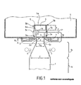
- the conveyor illustrated schematically in Figure 1 is used to transport, pneumatically, bottles 1 in line one behind the other.
- Each bottle 1 has a neck 1 a , corresponding to the neck of the bottle, which in the particular example illustrated is substantially cylindrical with diameter d , and is provided at its neck 1 a with an external flange 2 forming a protuberance.
- Each bottle 1 further comprises a main body 1 c of substantially cylindrical shape, extended by a tightening portion 1 b which extends to the neck 1 a and the section of which decreases in the direction of the flange 2.
- the bottles 1 are transported by being suspended on two guide rails 3, more commonly called under-neck guides.
- the conveyor comprises a blowing box 4, having a substantially rectangular section, and supplied in the usual way with pressurized air which has preferably been previously filtered.
- a blowing channel 5 of smaller cross section in the shape of an inverted U and delimited by an upper wall 5 a and two side walls 5 b .
- the blowing channel 5 communicates with the blowing box 4 by means of slots 5 c arranged in the side walls 5 b and judiciously distributed over the entire length of the blowing channel 5.
- the air under pressure inside the box 4 penetrates inside the blowing channel 5 while being directed on the bottles 1 above their flange 2, and thereby drives the bottles one behind the other in a direction transverse to the plane of Figure 1 , the bottles 1 being guided and supported during their transport by the under-neck guides 3.
- the transport air could also be blown in the direction of the body of the bottles, below their flange 2, being for example channeled between two vertical side walls located on either side of the bottle transport path.
- the conveyor is equipped with an attached longitudinal wedge 6, of constant thickness e .
- This shim 6 is fixed by any suitable means known on the inner face of the upper wall 5 a of the blowing channel 5.
- This shim 6 extends longitudinally over the entire length of the blowing channel 5.
- This shim 6 acts as a stop high and makes it possible to limit the ascent of the bottles between the under-neck guides 3.
- the choice of the thickness e of the wedge 6 makes it possible to fix the distance H separating the lower face 6 a from the wedge 6 with a high stop function, of the upper face 3 has under-neck guides 3, and thereby adjust the height of the upper stop as a function of the articles to be transported.
- the thickness e of the wedge 6 (that is to say in other words the distance H) is fixed so that there exists, between the lower face 6 a of the wedge 6 and l 'upper end 1 d of a bottle supported in vertical position by the under-neck guides 3 ( Figure 1), a residual clearance Jr which is strictly less than the contact height Hc, that is to say at the distance separating the sub-neck guides 3 and the contact section S c of the bottle.
- This contact section S c corresponds to the cross section of the tightening portion 1b of the bottle, the diameter of which is equal to the spacing Eg of the under-neck guides 3.
- the wedge 6 makes it possible, by limiting the ascent of a bottle 1, to reduce the risks of blocking of the bottles 1 in the accumulation phase when the bottles go up relative to each other under the compression effect which they exert on each other, or when the bottles go back up while rocking in docking phase.
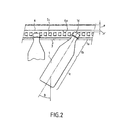
- the bottles 1 tend to oscillate back and forth around their vertical equilibrium position, in their direction of transport, according to a tilting angle referenced B in this figure.
- the maximum value of this angle B can for example advantageously be adjusted using longitudinal guides 7 (FIG. 1), which are positioned on either side of the bottle transport path, at the level of the tightening portion 1 b bottles, and whose spacing E is adjustable.
- the spacing E of the longitudinal guides 7, the maximum tilting angle forwards or backwards B of the bottles 1 is advantageously adjusted in their direction of transport.
- the two longitudinal guides 7 are adjusted in position so that the angle B is less than or equal to 30 °, which makes it possible to effectively limit the risks of blockage of a bottle 1 by tilting forward or backward in progress transport.
- the two guides 7 are preferably adjusted in position so that this angle B is greater than or equal to 10 °. It has been demonstrated that below a value of 10 ° for the tilting angle B, the bottles tended in a manner detrimental to their good conveying to be transported by oscillating in a jerky and too fast manner around their equilibrium position.
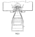
- the wedge 6 has been improved in that it has a longitudinal central recess 6 b in its lower face 6 a forming a longitudinal central channel.
- the width L of the recess 6 b is strictly less than the diameter D of the upper end 1 d of the bottle. This characteristic allows the lower face 6 a of the wedge 6 to fulfill its function of upper stop, in particular in the bottle accumulation phase, when a bottle 1 rises in vertical position relative to the guide rails 3.
- the part central hollowed out 6 b of the wedge 6 advantageously allows the front or rear tilting of the bottle 1 by an angle B, so that a portion of the end 1 d of the bottle rises in the channel formed by the recess 6 b , without coming into contact with the shim 6. Thanks to the structure of the shim 6 in FIG.
- the geometry of the recess 6 b (that is to say mainly the width L of the recess 6 b and its height h ) such so that there is a residual clearance Jr '( Figure 3) between the bottom wall 6 c of the recess 6 b and the upper end 1 d of a bottle 1 supported by the under-neck guides 3 at a given front or rear swing angle B.
- the geometry of the recess 6b will be chosen so that there is a residual clearance Jr 'when the bottle 1 is tilted at a tilting angle B front or rear equal to 45 °.
- blowing channel 5 of which has an upper wall 5 a in which a channel is provided longitudinal equivalent and fulfilling the same function as the central recess 6 b of the wedge 6.
- the height of the blowing channel is provided sufficiently low so that the underside of the wall 5 a , on either side of the central channel of this wall, fulfills the function of upper stop.
- an attached shim 6 which is not a solid shim in the thickness of which an obviously has been produced, but which is for example a sheet, shaped so to have a re-entrant channel fulfilling the same function as the central recess 6 b .
- an added shim 6 of thickness e calculated advantageously makes it possible to easily adapt the existing conveyors to a given type of bottles by judiciously choosing the thickness of the shim, in order to reduce the risks of blockage of the bottles. in the event of the bottles rising relative to the guide rails 3 of the conveyor.
- the geometry of the central recess 6 b of the wedge 6 is in the form of an inverted U, the side walls of the U being substantially orthogonal to the bottom 6 c of the recess. This geometry is not, however, limiting of the invention.
- the central recess 6 b could have any curved geometric shape, and for example in an arc of a circle, with a radius of curvature adapted to the radius of curvature of the upper end 1 d of the bottles 1.
- the wedge 6 of the variant in Figure 1 shows in this example a cross section of rectangular shape.
- the invention is of course not limited to this particular form of wedge 6, the cross section of the wedge 6 can be arbitrary, knowing that it suffices that there is a contact generator between the bottle and the wedge.
- the wedge 6 in the variant of Figure 1 could for example have a cylindrical, or semi-cylindrical cross section.
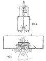
- FIG. 4 Another improved alternative embodiment of the invention has been illustrated in FIG. 4, in which the conveyor 4 is equipped with a longitudinal wedge 6, of small thickness, the height position of which is adjustable.
- the wedge 6 can be adjusted in height between two high and low positions, by means of a pneumatic cylinder 8 with two positions.
- the high position as illustrated in solid lines in FIG. 4, the shim 6 comes, for example, into contact with the upper wall 5 a of the blowing channel 5.
- the residual clearance existing between the bottles 1 and the wedge 6 is maximum; the bottles 1 can be transported freely without their upper end 1 d coming into contact with the wedge 6.
- the low position (as illustrated for example by dotted lines in FIG. 4), the residual clearance between the bottles and the wedge 6 is set to a minimum value.
- the air conveyor will be cut into a plurality of successive sections, each section comprising a wedge 6, the height of which can be adjusted independently with respect to the wedges 6 of the other sections.
- the sections of the conveyor in which the bottles are in the transport phase will be configured so that their wedge 6 is adjusted in the high position.
- the shims 6 of these sections will advantageously be adjusted in the low position, in order to reduce the risks of blockage of the accumulated bottles.
- the control of the jacks 8 associated with each wedge 6 can be automated from detection signals emitted by non-contact sensors of the photoelectric cell type or ultrasonic sensors, positioned respectively at each section, and allowing the automatic detection of an accumulation of bottles in a given section.
- the lower position of the wedge 6 of Figure 4 corresponds to the level of the lower face 6 a of the wedge 6 of Figure 3, and the position high corresponds to the level of the bottom 6 c of the longitudinal central recess 6 b of the wedge 6 of FIG. 3.
- the shim 6 can take several positions.
- This unlocking position is fixed according to the geometry of the bottles 1 so that in this position the wedge 6 is close enough to the under-neck guides 3 to allow the unlocking of a bottle 1 accidentally immobilized for example tilted forward or backward.
- the upper stop further comprises a longitudinal plate 6 d , which is housed in the obviously longitudinal 6 b of the wedge 6, and which is movable in translation in a vertical plane so that it can be adjusted in height. More particularly, the height position of this plate 6 d can be adjusted by means of a jack 8 'with two positions, between a high position (illustrated in solid lines) in which the plate 6 d is close to the bottom 6 c of the longitudinal course 6 b . This high position corresponds to the high position of the wedge 6 of the variant of FIG. 4. The low position (illustrated in dotted lines) corresponds to a position for unlocking the bottles 1.
- This position for unlocking the plate 6 d is located at an intermediate level between on the one hand the lower face 6 a of the wedge 6 and the upper end 1 d of a bottle 1 supported by the under-neck guides 3 in a vertical position.
- the plate 6 d when it is in the unlocked position, it is located at a distance H ′ with respect to the upper face 3 has under-neck guides 3 which is comprised on the one hand between the height H and on the other hand the height H b corresponding to the height of the upper part of the bottle 1, commonly called a drink, which extends between the upper end 1 d of the bottle 1 and collar 2 (including collar).
- the height H ′ will be provided slightly greater than the height H b .
- the height H ′ corresponding to the unlocking position of the plate 6 d must preferably be strictly greater than the height H b of the bottles 1, in order to avoid during unlocking operations a contact tightening the bottles 1 between plate 6 d and the under-neck guides 3.
Landscapes
- Physics & Mathematics (AREA)
- Engineering & Computer Science (AREA)
- Fluid Mechanics (AREA)
- Mechanical Engineering (AREA)
- Framework For Endless Conveyors (AREA)
- Attitude Control For Articles On Conveyors (AREA)
- Filling Of Jars Or Cans And Processes For Cleaning And Sealing Jars (AREA)
Description
- la figure 1 est une coupe transversale schématique d'une variante simplifiée non revendiquée d'un convoyeur à air selon l'invention, utilisé pour le transport de bouteilles, et mettant en oeuvre en guise de butée haute une cale rapportée d'épaisseur constante,
- la figure 2 schématise le jeu résiduel (Jr') existant entre la cale à fonction de butée haute et l'extrémité supérieure du col d'une bouteille inclinée d'un angle de basculement (B) par rapport à la verticale et dans la direction de transport,
- la figure 3 est une coupe transversale de principe d'une première variante perfectionnée d'un convoyeur à air de l'invention mettant en oeuvre une cale avec un évidement central formant un canal longitudinal,
- la figure 4 est une vue de principe d'une deuxième variante perfectionnée de réalisation d'un convoyeur à air selon l'invention, mettant en oeuvre une butée haute à hauteur réglable,
- et la figure 5 est une coupe de principe d'une troisième variante perfectionnée de réalisation d'un convoyeur à air selon l'invention, mettant en oeuvre une cale évidée avec plaque mobile à hauteur réglable.
Claims (12)
- Convoyeur à air pour articles pourvus d'une collerette (2) formant protubérance, ledit convoyeur comportant deux guides sous-col (3) espacés le long desquels les articles sont destinés à être transportés en étant suspendus sur les guides sous-col (3) par l'intermédiaire de leur collerette (2), caractérisé en ce qu'il comprend au-dessus des guides sous-col (3) une butée longitudinale (6), qui a pour fonction de limiter la remontée des articles entre les guides sous-col (3), et qui comprend un canal (6b) central longitudinal.
- Convoyeur selon la revendication 1 pour articles comportant au-dessous de leur collerette (2) une portion de resserrement (1b) dont la section décroít en direction de la collerette, et passe par une section de contact (Sc) dont le diamètre est égal à l'écartement (Eg) des guides sous-col (3), caractérisé en ce que la butée (6) est prévue à une distance (H) des guides sous-col (3) qui est telle qu'il existe, entre la butée (6) et l'extrémité supérieure d'un article supporté en position verticale par les guides sous-col (3), un jeu résiduel (Jr) qui est strictement inférieur à la hauteur de contact (Hc) séparant les guides sous-col (3) et la section de contact (Sc) de cet article en position verticale.
- Convoyeur selon la revendication 1 ou 2 caractérisé en ce que la largeur (L) du canal (6b) est strictement inférieure au diamètre (D) d'un article au niveau de son extrémité supérieure (1d).
- Convoyeur selon l'une des revendications 1 à 3 caractérisé en ce que la géométrie du canal (6b) est prévue de telle sorte qu'il existe un jeu résiduel (Jr') entre la butée (6) et l'extrémité supérieure d'un article supporté par les guides sous-col (3) selon un angle de basculement avant ou arrière de 45°.
- Convoyeur selon l'une des revendications 1 à 4 caractérisé en ce qu'il comprend un plaque longitudinale (6d), qui est montée au droit du canal central (6b) et dont la position en hauteur est réglable.
- Convoyeur selon la revendication 5 caractérisé en ce que la plaque (6d) est prévue pour être réglée en hauteur dans au moins deux positionsune position haute dans laquelle la plaque (6d) est logée dans le canal central (6b),une position basse de déblocage des articles dans laquelle la plaque (6d) est située au-dessous du niveau de la face inférieure (6a) de la butée (6).
- Convoyeur selon l'une des revendications 1 à 6 caractérisé en ce que la butée (6) est constituée par une cale rapportée.
- Convoyeur selon l'une des revendications 1 à 6 comportant un canal de soufflage (5) et caractérisé en ce que la butée (6) est constituée par la paroi supérieure (5a) du canal de soufflage (5).
- Convoyeur selon l'une des revendications 1 à 8 caractérisé en ce que la butée (6) est constituée par une tôle mise en forme en sorte de comporter un canal rentrant.
- Convoyeur selon l'une des revendications 1 à 7 caractérisé en ce que la butée (6) est constituée par deux éléments longitudinaux distincts séparés par le canal central longitudinal (6b).
- Convoyeur selon l'une des revendications 1 à 10 caractérisé en ce qu'il comprend en outre deux guides longitudinaux supérieurs (7) qui sont positionnés de part et d'autre du trajet des articles, et qui ont pour fonction de limiter l'angle (B) de basculement avant ou arrière des articles dans un plan vertical et dans leur direction de transport.
- Convoyeur selon la revendication 11 caractérisé en ce que les deux guides supérieurs (7) sont réglés en positions de telle sorte que l'angle de balancement avant ou arrière (B) d'un article en cours de transport est d'une part inférieur ou égal à 30°, et de préférence inférieur ou égal à 25°, et d'autre part supérieur ou égal à 10°.
Applications Claiming Priority (3)
| Application Number | Priority Date | Filing Date | Title |
|---|---|---|---|
| FR9710770 | 1997-08-25 | ||
| FR9710770A FR2767517B1 (fr) | 1997-08-25 | 1997-08-25 | Convoyeur pour recipients avec guides permettant de limiter le basculement des recipients par rapport a la verticale dans leur direction de transport |
| EP98940335A EP1007456B1 (fr) | 1997-08-25 | 1998-07-24 | Convoyeur pour transporter des articles pourvus d'une collerette ou similaire |
Related Parent Applications (1)
| Application Number | Title | Priority Date | Filing Date |
|---|---|---|---|
| EP98940335A Division EP1007456B1 (fr) | 1997-08-25 | 1998-07-24 | Convoyeur pour transporter des articles pourvus d'une collerette ou similaire |
Publications (3)
| Publication Number | Publication Date |
|---|---|
| EP1207124A1 EP1207124A1 (fr) | 2002-05-22 |
| EP1207124B1 true EP1207124B1 (fr) | 2003-10-22 |
| EP1207124B2 EP1207124B2 (fr) | 2009-09-16 |
Family
ID=9510576
Family Applications (2)
| Application Number | Title | Priority Date | Filing Date |
|---|---|---|---|
| EP98940335A Expired - Lifetime EP1007456B1 (fr) | 1997-08-25 | 1998-07-24 | Convoyeur pour transporter des articles pourvus d'une collerette ou similaire |
| EP01130946A Expired - Lifetime EP1207124B2 (fr) | 1997-08-25 | 1998-07-24 | Convoyeur permettant le transport d'articles pourvus d'une collerette ou similaire |
Family Applications Before (1)
| Application Number | Title | Priority Date | Filing Date |
|---|---|---|---|
| EP98940335A Expired - Lifetime EP1007456B1 (fr) | 1997-08-25 | 1998-07-24 | Convoyeur pour transporter des articles pourvus d'une collerette ou similaire |
Country Status (9)
| Country | Link |
|---|---|
| US (1) | US6488449B1 (fr) |
| EP (2) | EP1007456B1 (fr) |
| JP (1) | JP3983474B2 (fr) |
| AU (1) | AU8868298A (fr) |
| DE (4) | DE1207124T1 (fr) |
| ES (2) | ES2210088T5 (fr) |
| FR (1) | FR2767517B1 (fr) |
| MX (1) | MXPA04002053A (fr) |
| WO (1) | WO1999010263A1 (fr) |
Families Citing this family (29)
| Publication number | Priority date | Publication date | Assignee | Title |
|---|---|---|---|---|
| IT1305257B1 (it) * | 1998-01-15 | 2001-04-19 | Sipa Spa | Impianto perfezionato per il trasferimento ordinato sequenziale dicontenitori in resina termoplastica. |
| IT1308585B1 (it) * | 1999-12-23 | 2002-01-08 | Lino Lanfranchi | Apparato per il trasporto sospeso di contenitori provvisti di collaresporgente. |
| FR2806068A1 (fr) | 2000-03-08 | 2001-09-14 | Netra Systems | Procede de transport d'articles en position inclinee vers l'arriere entre deux rails de guidage et sous l'action de jets d'air, et convoyeur a air pour la mise en oeuvre de ce procede |
| FR2806067A1 (fr) | 2000-03-08 | 2001-09-14 | Netra Systems | Procede de transport d'articles entre deux rails de guidage sous l'action de jets d'air et convoyeur a air pour la mise en oeuvre de ce procede |
| DE20112256U1 (de) | 2001-07-25 | 2002-12-05 | KRONES AG, 93073 Neutraubling | Luftförderer |
| JP4017898B2 (ja) * | 2002-03-18 | 2007-12-05 | 東洋自動機株式会社 | スパウト又はスパウト付き袋の搬送装置 |
| DE60212720T2 (de) * | 2002-04-16 | 2007-06-28 | Amcor Ltd., Abbotsford | Fördervorrichtung und verfahren zur hängenden förderung von behältern |
| US6736573B1 (en) * | 2002-10-30 | 2004-05-18 | Goldco Industries, Inc. | Selective conveying of unstable articles having a neck ring |
| DE60321492D1 (de) * | 2003-01-06 | 2008-07-17 | Fujirebio Kk | Vorrichtung zur entnahme eines stabförmigen werkstückes mit einem breiten ende |
| FR2854152A1 (fr) | 2003-04-25 | 2004-10-29 | Netra Systems | Systeme a positionnement reglable pour convoyeur, et notamment systeme de guidage reglable, et convoyeur equipe de ce systeme |
| AU2003246863A1 (en) | 2003-04-25 | 2004-11-23 | Netra Systems | Adjustable positioning system for a conveyor |
| DE102004055098A1 (de) * | 2004-11-15 | 2006-05-24 | Krones Ag | Behälterumgreifer |
| FR2890062B1 (fr) * | 2005-08-29 | 2008-10-31 | Sidel Sas | Dispositif de chargement ou de dechargement de recipients comportant un col sur un element de transport |
| FR2890061A1 (en) * | 2005-08-29 | 2007-03-02 | Sidel Sas | Container loader for transporter has ejector for incorrectly loaded containers equipped with receiver synchronised with movement of gripper |
| DE102005043436B4 (de) * | 2005-09-13 | 2014-02-13 | Schaeffler Technologies AG & Co. KG | Radlagereinheit für Kraftfahrzeuge und Verfahren zur Herstellung desselben |
| US7481606B2 (en) * | 2006-06-08 | 2009-01-27 | Freddy Robert Lyons | System, method, and apparatus for air-propelled conveyance of workpieces in sanitary environments |
| JP5135916B2 (ja) * | 2007-06-29 | 2013-02-06 | 澁谷工業株式会社 | エア搬送コンベヤ |
| JP2009035356A (ja) * | 2007-07-31 | 2009-02-19 | Suntory Ltd | ボトル搬送装置およびボトル搬送方法 |
| CH704401A1 (de) * | 2011-01-28 | 2012-07-31 | M Tanner Ag | Fördereinrichtung für zylindrische Körper, mit in Förderrichtung geneigten Ablaufschienen. |
| DE102011056441A1 (de) * | 2011-12-14 | 2013-06-20 | Krones Ag | Vorrichtung zum Transportieren von Kunststoffvorformlingen |
| CA2882922C (fr) * | 2014-02-21 | 2020-12-01 | Septimatech Group Inc. | Systeme de rail-guide comportant un element de couvercle |
| FR3028254B1 (fr) * | 2014-11-10 | 2019-04-12 | Sidel Participations | Procede de transport de preformes de recipients en matiere plastique |
| DE102015205984A1 (de) * | 2015-04-02 | 2016-10-06 | Krones Aktiengesellschaft | Verfahren und Führungssystem für den Transport von Behältern oder Behälter-komponenten in Industrieanlagen für die Behälterherstellung und/oder Produktabfüllung |
| FR3051780A1 (fr) * | 2016-05-25 | 2017-12-01 | Sidel Participations | Procede de deblocage du defilement de corps creux dans un convoyeur a glissiere |
| US9884733B1 (en) * | 2017-08-11 | 2018-02-06 | Flexibility Engineering, Llc | Conveyed bottle guide apparatus and method |
| WO2020150413A1 (fr) * | 2019-01-18 | 2020-07-23 | Société des Produits Nestlé S.A. | Systèmes, procédés et dispositifs permettant le déblocage d'une chaîne de fabrication |
| FR3102702B1 (fr) * | 2019-11-05 | 2021-11-05 | Sidel Participations | Procédé de guidage d'une préforme redressée dans un interstice d'un dispositif d'alignement et de redressement de préformes et dispositif d'alignement et de redressement associé |
| CN113264368B (zh) * | 2021-06-16 | 2022-10-11 | 上海紫泉饮料工业有限公司 | 一种防止塑料瓶堵塞的连续输送通道 |
| DE102023109658A1 (de) * | 2023-04-18 | 2024-10-24 | Krones Aktiengesellschaft | Vorrichtung und Verfahren zum Transportieren von Kunststoffvorformlingen mit Störungsbeseitigung |
Citations (1)
| Publication number | Priority date | Publication date | Assignee | Title |
|---|---|---|---|---|
| WO1990010587A1 (fr) * | 1989-03-08 | 1990-09-20 | Sarcmi S.P.A. | Bande transporteuse avec buses d'air combinees |
Family Cites Families (26)
| Publication number | Priority date | Publication date | Assignee | Title |
|---|---|---|---|---|
| GB2092981B (en) | 1981-02-14 | 1985-01-09 | Smith Dennis Claude | Air-bed conveyers |
| US4822214A (en) * | 1987-06-12 | 1989-04-18 | Aidlin Automation Corp. | Air conveyor |
| DE8807146U1 (de) * | 1988-06-01 | 1988-08-18 | Holstein Und Kappert Ag, 4600 Dortmund | Vorrichtung zum Transportieren von Flaschen |
| NL9001589A (nl) † | 1990-07-12 | 1992-02-03 | Smit Gerardus | Transportinrichting voor flessen. |
| US5161919A (en) * | 1991-08-06 | 1992-11-10 | Simplimatic Engineering Company | Bottle air conveyor |
| US5246314A (en) * | 1991-08-06 | 1993-09-21 | Simplimatic Engineering Company | Bottle air conveyor with adjustable guides |
| US5248045A (en) * | 1991-12-12 | 1993-09-28 | The Coca-Cola Company | Method and apparatus for uncasing and sorting bottles |
| US5553080A (en) * | 1992-08-13 | 1996-09-03 | Nec Corporation | Speech decoding apparatus comprising alarm signal generator operable on deterioration of transmission path quality |
| US5484237A (en) * | 1992-12-29 | 1996-01-16 | Langenbeck; Keith A. | Pneumatic conveyor apparatus having air deflectors |
| US5437521A (en) * | 1993-05-13 | 1995-08-01 | Ouellette Machinery Systems, Inc. | Air conveyor for bottles |
| US5421678A (en) * | 1993-06-28 | 1995-06-06 | Aidlin; Samuel S. | Method and apparatus for conveying bottles |
| US5542789A (en) * | 1994-02-22 | 1996-08-06 | Aidlin; Stephen H. | Multi position bottle guide assembly |
| US5516239A (en) * | 1994-02-22 | 1996-05-14 | Pak Air, Inc. | Bottle conveyor |
| US5501552A (en) * | 1994-04-29 | 1996-03-26 | Goldco Industries, Inc. | Conveying system for unstable articles having a neck ring |
| CA2149620A1 (fr) * | 1994-05-24 | 1995-11-25 | Donald J. Simkowski | Transporteur reglable en hauteur |
| US5553698A (en) * | 1994-12-28 | 1996-09-10 | J And J Container Handling Systems | Conveyor belt apparatus for bottles |
| US5567091A (en) * | 1995-05-02 | 1996-10-22 | R. A. Pearson Company | Swing-arm air conveyor and flexible guide joint for conveying bottles with neck flanges |
| ES2145643B1 (es) * | 1996-02-15 | 2001-02-16 | Sala Jaime Marti | Dispositivo para el transporte de botellas vacias en suspension. |
| US5584614A (en) * | 1996-02-28 | 1996-12-17 | Aidlin; Stephen H. | Air handling system for a pneumatic conveyor |
| US5695302A (en) * | 1996-03-15 | 1997-12-09 | Simplimatic Engineering Company | Thrust slot neck-guided air conveyor |
| US5785169A (en) * | 1996-10-18 | 1998-07-28 | Vt Zurich Marketing Pte. Ltd. | Conveyor assembly of the conveying of open containers |
| US6062773A (en) * | 1997-01-31 | 2000-05-16 | Oullette Machinery Systems, Inc. | Infeed assembly for use with an air conveyor system |
| US5947647A (en) * | 1997-01-31 | 1999-09-07 | Ouellette Machinery Systems, Inc. | Conveyor coupling |
| US5951211A (en) * | 1997-06-16 | 1999-09-14 | Oullette Machinery Systems, Inc. | Air conveyor having transitional section |
| US6024518A (en) * | 1998-03-04 | 2000-02-15 | Ouellette Machinery Systems, Inc. | Air conveyor with conveyed object hold down guide rail |
| US6190094B1 (en) * | 1999-06-02 | 2001-02-20 | Plastipak Packaging, Inc. | Pneumatic conveying apparatus |
-
1997
- 1997-08-25 FR FR9710770A patent/FR2767517B1/fr not_active Expired - Fee Related
-
1998
- 1998-07-24 DE DE1207124T patent/DE1207124T1/de active Pending
- 1998-07-24 ES ES01130946T patent/ES2210088T5/es not_active Expired - Lifetime
- 1998-07-24 US US09/486,352 patent/US6488449B1/en not_active Expired - Fee Related
- 1998-07-24 EP EP98940335A patent/EP1007456B1/fr not_active Expired - Lifetime
- 1998-07-24 WO PCT/FR1998/001646 patent/WO1999010263A1/fr not_active Ceased
- 1998-07-24 DE DE1007456T patent/DE1007456T1/de active Pending
- 1998-07-24 ES ES98940335T patent/ES2186205T3/es not_active Expired - Lifetime
- 1998-07-24 DE DE69819214T patent/DE69819214T3/de not_active Expired - Lifetime
- 1998-07-24 JP JP2000507604A patent/JP3983474B2/ja not_active Expired - Fee Related
- 1998-07-24 DE DE69808783T patent/DE69808783T2/de not_active Expired - Lifetime
- 1998-07-24 EP EP01130946A patent/EP1207124B2/fr not_active Expired - Lifetime
- 1998-07-24 AU AU88682/98A patent/AU8868298A/en not_active Abandoned
-
2004
- 2004-03-03 MX MXPA04002053A patent/MXPA04002053A/es not_active Application Discontinuation
Patent Citations (1)
| Publication number | Priority date | Publication date | Assignee | Title |
|---|---|---|---|---|
| WO1990010587A1 (fr) * | 1989-03-08 | 1990-09-20 | Sarcmi S.P.A. | Bande transporteuse avec buses d'air combinees |
Also Published As
| Publication number | Publication date |
|---|---|
| ES2186205T3 (es) | 2003-05-01 |
| FR2767517B1 (fr) | 2001-03-02 |
| JP2001514141A (ja) | 2001-09-11 |
| WO1999010263A1 (fr) | 1999-03-04 |
| EP1207124B2 (fr) | 2009-09-16 |
| ES2210088T5 (es) | 2010-01-21 |
| MXPA04002053A (es) | 2004-06-25 |
| EP1207124A1 (fr) | 2002-05-22 |
| FR2767517A1 (fr) | 1999-02-26 |
| DE1007456T1 (de) | 2001-03-01 |
| EP1007456A1 (fr) | 2000-06-14 |
| JP3983474B2 (ja) | 2007-09-26 |
| DE69808783T2 (de) | 2003-06-26 |
| DE69819214T3 (de) | 2010-04-01 |
| EP1007456B1 (fr) | 2002-10-16 |
| DE1207124T1 (de) | 2003-01-09 |
| DE69819214D1 (de) | 2003-11-27 |
| DE69808783D1 (de) | 2002-11-21 |
| ES2210088T3 (es) | 2004-07-01 |
| DE69819214T2 (de) | 2004-08-26 |
| US6488449B1 (en) | 2002-12-03 |
| AU8868298A (en) | 1999-03-16 |
Similar Documents
| Publication | Publication Date | Title |
|---|---|---|
| EP1207124B1 (fr) | Convoyeur permettant le transport d'articles pourvus d'une collerette ou similaire | |
| EP1263666B1 (fr) | Tron on courbe de convoyeur avec rails de guidage a ecartement reglable | |
| EP1697238B1 (fr) | Systeme d'alimentation de preformes comportant un dispositif d'elimination selective des preformes mal positionnees de type allonge | |
| EP1255687B1 (fr) | Convoyeur a air equipe d'un guide inferieur | |
| EP0511048B1 (fr) | Dispositif de convoyage de préformes agencé pour éliminer des préformes emboîtées les unes dans les autres | |
| CA2312038C (fr) | Dispositif de convoyage de produits, notamment de fruits, destine a l'alimentation d'une unite de tri desdits produits | |
| EP2978697B1 (fr) | Procede et systeme de transfert d'objets | |
| WO2002036466A1 (fr) | Systeme d"alimentation de preformes destine notamment a une machine de soufflage de recipients | |
| EP1097097A1 (fr) | Convoyeur a air pour le transport d'articles suspendus et procedes de deblocage, de ralentissement, d'immobilisation ou de cadencement d'articles | |
| FR2911587A1 (fr) | DISPOSITIF DE CONVOYAGE D'OBJETS, NOTAMMENT PREFORMES, BOUTEILLES OU ANALOGUES, PAR SOUFFLAGE D'air | |
| EP3464132A1 (fr) | Procede de deblocage du defilement de corps creux dans un convoyeur a glissiere | |
| WO2006077287A1 (fr) | Convoyeur a air pour articles suspendus avec poutre porteuse pour accessoires de convoyage | |
| EP3166877B1 (fr) | Dispositif d'alimentation de préformes comportant une glissière de défilement équipée de butées latérales pour arrêter des préformes couchées | |
| FR2669311A1 (fr) | Dispositif d'accumulation dynamique de recipients dans une chaine de transfert par jets d'air. | |
| CA3237183A1 (fr) | Dispositif de guidage lateral d'une bande transporteuse sans fin de convoyeur auge | |
| FR2818624A1 (fr) | Systeme de manutention | |
| WO2004096680A1 (fr) | Systeme a positionnement reglable pour convoyeur | |
| WO2001066447A1 (fr) | Procede de transport d'articles, et convoyeur a air pour la mise en oeuvre de ce procede | |
| EP3986813B1 (fr) | Dispositif de convoyage et installation de traitement de produits | |
| FR2571030A1 (fr) | Procede et dispositif de redressement de recipients et installation de redressement de recipients | |
| FR2806067A1 (fr) | Procede de transport d'articles entre deux rails de guidage sous l'action de jets d'air et convoyeur a air pour la mise en oeuvre de ce procede | |
| FR2799454A1 (fr) | Procede et dispositif de convoyage d'objets en position suspendue | |
| FR2854152A1 (fr) | Systeme a positionnement reglable pour convoyeur, et notamment systeme de guidage reglable, et convoyeur equipe de ce systeme | |
| EP1220807A1 (fr) | Dispositif de convoyage d'emballages creux dans une ligne de traitement automatique. | |
| FR2513173A1 (fr) | Chariot de coupe pour trancheuse verticale |
Legal Events
| Date | Code | Title | Description |
|---|---|---|---|
| PUAI | Public reference made under article 153(3) epc to a published international application that has entered the european phase |
Free format text: ORIGINAL CODE: 0009012 |
|
| AC | Divisional application: reference to earlier application |
Ref document number: 1007456 Country of ref document: EP |
|
| 17P | Request for examination filed |
Effective date: 20020408 |
|
| GRAH | Despatch of communication of intention to grant a patent |
Free format text: ORIGINAL CODE: EPIDOS IGRA |
|
| DET | De: translation of patent claims | ||
| GRAH | Despatch of communication of intention to grant a patent |
Free format text: ORIGINAL CODE: EPIDOS IGRA |
|
| AKX | Designation fees paid |
Designated state(s): BE DE ES FR GB IT NL |
|
| GRAA | (expected) grant |
Free format text: ORIGINAL CODE: 0009210 |
|
| AC | Divisional application: reference to earlier application |
Ref document number: 1007456 Country of ref document: EP Kind code of ref document: P |
|
| AK | Designated contracting states |
Kind code of ref document: B1 Designated state(s): BE DE ES FR GB IT NL |
|
| REG | Reference to a national code |
Ref country code: GB Ref legal event code: FG4D Free format text: NOT ENGLISH |
|
| REF | Corresponds to: |
Ref document number: 69819214 Country of ref document: DE Date of ref document: 20031127 Kind code of ref document: P |
|
| GBT | Gb: translation of ep patent filed (gb section 77(6)(a)/1977) |
Effective date: 20031112 |
|
| REG | Reference to a national code |
Ref country code: ES Ref legal event code: FG2A Ref document number: 2210088 Country of ref document: ES Kind code of ref document: T3 |
|
| PLBQ | Unpublished change to opponent data |
Free format text: ORIGINAL CODE: EPIDOS OPPO |
|
| PLBI | Opposition filed |
Free format text: ORIGINAL CODE: 0009260 |
|
| PLAX | Notice of opposition and request to file observation + time limit sent |
Free format text: ORIGINAL CODE: EPIDOSNOBS2 |
|
| 26 | Opposition filed |
Opponent name: KRONES AGSTOCKMAIR & SCHWANHAEUSSERANWALTSSOZIE Effective date: 20040722 |
|
| NLR1 | Nl: opposition has been filed with the epo |
Opponent name: KRONES AG |
|
| PLAX | Notice of opposition and request to file observation + time limit sent |
Free format text: ORIGINAL CODE: EPIDOSNOBS2 |
|
| PLAX | Notice of opposition and request to file observation + time limit sent |
Free format text: ORIGINAL CODE: EPIDOSNOBS2 |
|
| PLBB | Reply of patent proprietor to notice(s) of opposition received |
Free format text: ORIGINAL CODE: EPIDOSNOBS3 |
|
| PLAY | Examination report in opposition despatched + time limit |
Free format text: ORIGINAL CODE: EPIDOSNORE2 |
|
| PLBC | Reply to examination report in opposition received |
Free format text: ORIGINAL CODE: EPIDOSNORE3 |
|
| APBP | Date of receipt of notice of appeal recorded |
Free format text: ORIGINAL CODE: EPIDOSNNOA2O |
|
| APAH | Appeal reference modified |
Free format text: ORIGINAL CODE: EPIDOSCREFNO |
|
| APBQ | Date of receipt of statement of grounds of appeal recorded |
Free format text: ORIGINAL CODE: EPIDOSNNOA3O |
|
| REG | Reference to a national code |
Ref country code: FR Ref legal event code: GC |
|
| APBU | Appeal procedure closed |
Free format text: ORIGINAL CODE: EPIDOSNNOA9O |
|
| RAP2 | Party data changed (patent owner data changed or rights of a patent transferred) |
Owner name: NTS SAS |
|
| REG | Reference to a national code |
Ref country code: FR Ref legal event code: TP |
|
| NLT2 | Nl: modifications (of names), taken from the european patent patent bulletin |
Owner name: NTS SAS Effective date: 20080813 |
|
| PGFP | Annual fee paid to national office [announced via postgrant information from national office to epo] |
Ref country code: NL Payment date: 20080711 Year of fee payment: 11 Ref country code: IT Payment date: 20080719 Year of fee payment: 11 |
|
| REG | Reference to a national code |
Ref country code: GB Ref legal event code: 732E |
|
| PGFP | Annual fee paid to national office [announced via postgrant information from national office to epo] |
Ref country code: GB Payment date: 20080630 Year of fee payment: 11 |
|
| PUAH | Patent maintained in amended form |
Free format text: ORIGINAL CODE: 0009272 |
|
| STAA | Information on the status of an ep patent application or granted ep patent |
Free format text: STATUS: PATENT MAINTAINED AS AMENDED |
|
| 27A | Patent maintained in amended form |
Effective date: 20090916 |
|
| AK | Designated contracting states |
Kind code of ref document: B2 Designated state(s): BE DE ES FR GB IT NL |
|
| NLR2 | Nl: decision of opposition |
Effective date: 20090916 |
|
| REG | Reference to a national code |
Ref country code: ES Ref legal event code: DC2A Date of ref document: 20091116 Kind code of ref document: T5 |
|
| PG25 | Lapsed in a contracting state [announced via postgrant information from national office to epo] |
Ref country code: NL Free format text: LAPSE BECAUSE OF FAILURE TO SUBMIT A TRANSLATION OF THE DESCRIPTION OR TO PAY THE FEE WITHIN THE PRESCRIBED TIME-LIMIT Effective date: 20031022 |
|
| NLV1 | Nl: lapsed or annulled due to failure to fulfill the requirements of art. 29p and 29m of the patents act | ||
| GBPC | Gb: european patent ceased through non-payment of renewal fee |
Effective date: 20090724 |
|
| PG25 | Lapsed in a contracting state [announced via postgrant information from national office to epo] |
Ref country code: GB Free format text: LAPSE BECAUSE OF NON-PAYMENT OF DUE FEES Effective date: 20090724 |
|
| PG25 | Lapsed in a contracting state [announced via postgrant information from national office to epo] |
Ref country code: IT Free format text: LAPSE BECAUSE OF NON-PAYMENT OF DUE FEES Effective date: 20090724 |
|
| REG | Reference to a national code |
Ref country code: FR Ref legal event code: PLFP Year of fee payment: 18 |
|
| REG | Reference to a national code |
Ref country code: FR Ref legal event code: PLFP Year of fee payment: 19 |
|
| REG | Reference to a national code |
Ref country code: FR Ref legal event code: PLFP Year of fee payment: 20 |
|
| PGFP | Annual fee paid to national office [announced via postgrant information from national office to epo] |
Ref country code: DE Payment date: 20170719 Year of fee payment: 20 Ref country code: FR Payment date: 20170720 Year of fee payment: 20 Ref country code: ES Payment date: 20170802 Year of fee payment: 20 |
|
| PGFP | Annual fee paid to national office [announced via postgrant information from national office to epo] |
Ref country code: BE Payment date: 20170721 Year of fee payment: 20 |
|
| REG | Reference to a national code |
Ref country code: DE Ref legal event code: R071 Ref document number: 69819214 Country of ref document: DE |
|
| REG | Reference to a national code |
Ref country code: BE Ref legal event code: MK Effective date: 20180724 |
|
| REG | Reference to a national code |
Ref country code: ES Ref legal event code: FD2A Effective date: 20201203 |
|
| PG25 | Lapsed in a contracting state [announced via postgrant information from national office to epo] |
Ref country code: ES Free format text: LAPSE BECAUSE OF EXPIRATION OF PROTECTION Effective date: 20180725 |