EP1207124B1 - Conveyor for transporting articles provided with a flange or the like - Google Patents
Conveyor for transporting articles provided with a flange or the like Download PDFInfo
- Publication number
- EP1207124B1 EP1207124B1 EP01130946A EP01130946A EP1207124B1 EP 1207124 B1 EP1207124 B1 EP 1207124B1 EP 01130946 A EP01130946 A EP 01130946A EP 01130946 A EP01130946 A EP 01130946A EP 1207124 B1 EP1207124 B1 EP 1207124B1
- Authority
- EP
- European Patent Office
- Prior art keywords
- articles
- stop
- under
- guides
- conveyor
- Prior art date
- Legal status (The legal status is an assumption and is not a legal conclusion. Google has not performed a legal analysis and makes no representation as to the accuracy of the status listed.)
- Expired - Lifetime
Links
- 238000007664 blowing Methods 0.000 claims description 15
- 230000003247 decreasing effect Effects 0.000 claims 1
- 239000002184 metal Substances 0.000 claims 1
- 238000009825 accumulation Methods 0.000 description 11
- 230000000903 blocking effect Effects 0.000 description 7
- 239000004033 plastic Substances 0.000 description 3
- 238000001514 detection method Methods 0.000 description 2
- 230000006835 compression Effects 0.000 description 1
- 238000007906 compression Methods 0.000 description 1
- 230000007423 decrease Effects 0.000 description 1
- 230000001627 detrimental effect Effects 0.000 description 1
- 238000006073 displacement reaction Methods 0.000 description 1
- 230000000694 effects Effects 0.000 description 1
- PCHJSUWPFVWCPO-UHFFFAOYSA-N gold Chemical compound [Au] PCHJSUWPFVWCPO-UHFFFAOYSA-N 0.000 description 1
- 239000010931 gold Substances 0.000 description 1
- 229910052737 gold Inorganic materials 0.000 description 1
- 238000004519 manufacturing process Methods 0.000 description 1
- 238000003032 molecular docking Methods 0.000 description 1
- 238000004806 packaging method and process Methods 0.000 description 1
- 230000000630 rising effect Effects 0.000 description 1
- 239000011435 rock Substances 0.000 description 1
- 239000007787 solid Substances 0.000 description 1
- 230000003068 static effect Effects 0.000 description 1
- 239000000725 suspension Substances 0.000 description 1
- 229920005992 thermoplastic resin Polymers 0.000 description 1
- 238000011144 upstream manufacturing Methods 0.000 description 1
Images
Classifications
-
- B—PERFORMING OPERATIONS; TRANSPORTING
- B65—CONVEYING; PACKING; STORING; HANDLING THIN OR FILAMENTARY MATERIAL
- B65G—TRANSPORT OR STORAGE DEVICES, e.g. CONVEYORS FOR LOADING OR TIPPING, SHOP CONVEYOR SYSTEMS OR PNEUMATIC TUBE CONVEYORS
- B65G51/00—Conveying articles through pipes or tubes by fluid flow or pressure; Conveying articles over a flat surface, e.g. the base of a trough, by jets located in the surface
- B65G51/02—Directly conveying the articles, e.g. slips, sheets, stockings, containers or workpieces, by flowing gases
- B65G51/03—Directly conveying the articles, e.g. slips, sheets, stockings, containers or workpieces, by flowing gases over a flat surface or in troughs
- B65G51/035—Directly conveying the articles, e.g. slips, sheets, stockings, containers or workpieces, by flowing gases over a flat surface or in troughs for suspended articles, e.g. bottles
-
- B—PERFORMING OPERATIONS; TRANSPORTING
- B65—CONVEYING; PACKING; STORING; HANDLING THIN OR FILAMENTARY MATERIAL
- B65G—TRANSPORT OR STORAGE DEVICES, e.g. CONVEYORS FOR LOADING OR TIPPING, SHOP CONVEYOR SYSTEMS OR PNEUMATIC TUBE CONVEYORS
- B65G2201/00—Indexing codes relating to handling devices, e.g. conveyors, characterised by the type of product or load being conveyed or handled
- B65G2201/02—Articles
- B65G2201/0235—Containers
- B65G2201/0244—Bottles
- B65G2201/0247—Suspended bottles
Definitions
- the present invention relates to the conveyance of articles comprising a collar or the like, forming a protuberance, and allowing their suspension during transport. It has more particularly for object a conveyor in which the articles are transported while hanging via their flange on two under-neck guides serving guide rails, and being more particularly propelled each behind the others by means of an air flow. It mainly finds its application to the transport of light plastic articles, such as containers (flasks or bottles, etc.) made of PET, PVC, etc., in particular during the packaging operations of these articles, the conveyor being for example used to ship empty containers online from an upstream machine for manufacturing these containers (blower) up to a downstream machine for filling containers (filling machine).
- thermoplastic resin constituting the walls plastic items from the snowblower are in such a condition that walls of these items are sticky, and that just rubbing a article in relation to each other when raising the articles, results in bonding of the articles between them.
- Another cause of blockage of articles in accumulation phase is linked to the fact that an item arriving with a high speed in contact with a train of accumulated articles, tends to tilt significantly compared to the transport direction in building on the last item of the accumulated train. The following article then comes to rest against the base of this article inclined in the direction transport, and exerts on it a mechanical thrust which tends to bring it up between the under-neck guides and lock it in position inclined.
- the present invention provides a new solution for reduce the risk of blocking items, especially in phase accumulation, while overcoming the two aforementioned inherent drawbacks the implementation of upper shoulder guides with stop function such that it is taught in patent US 5,421,678. This solution is obtained by the conveyor of claim 1.
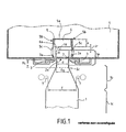
- the conveyor illustrated schematically in Figure 1 is used to transport, pneumatically, bottles 1 in line one behind the other.
- Each bottle 1 has a neck 1 a , corresponding to the neck of the bottle, which in the particular example illustrated is substantially cylindrical with diameter d , and is provided at its neck 1 a with an external flange 2 forming a protuberance.
- Each bottle 1 further comprises a main body 1 c of substantially cylindrical shape, extended by a tightening portion 1 b which extends to the neck 1 a and the section of which decreases in the direction of the flange 2.
- the bottles 1 are transported by being suspended on two guide rails 3, more commonly called under-neck guides.
- the conveyor comprises a blowing box 4, having a substantially rectangular section, and supplied in the usual way with pressurized air which has preferably been previously filtered.
- a blowing channel 5 of smaller cross section in the shape of an inverted U and delimited by an upper wall 5 a and two side walls 5 b .
- the blowing channel 5 communicates with the blowing box 4 by means of slots 5 c arranged in the side walls 5 b and judiciously distributed over the entire length of the blowing channel 5.
- the air under pressure inside the box 4 penetrates inside the blowing channel 5 while being directed on the bottles 1 above their flange 2, and thereby drives the bottles one behind the other in a direction transverse to the plane of Figure 1 , the bottles 1 being guided and supported during their transport by the under-neck guides 3.
- the transport air could also be blown in the direction of the body of the bottles, below their flange 2, being for example channeled between two vertical side walls located on either side of the bottle transport path.
- the conveyor is equipped with an attached longitudinal wedge 6, of constant thickness e .
- This shim 6 is fixed by any suitable means known on the inner face of the upper wall 5 a of the blowing channel 5.
- This shim 6 extends longitudinally over the entire length of the blowing channel 5.
- This shim 6 acts as a stop high and makes it possible to limit the ascent of the bottles between the under-neck guides 3.
- the choice of the thickness e of the wedge 6 makes it possible to fix the distance H separating the lower face 6 a from the wedge 6 with a high stop function, of the upper face 3 has under-neck guides 3, and thereby adjust the height of the upper stop as a function of the articles to be transported.
- the thickness e of the wedge 6 (that is to say in other words the distance H) is fixed so that there exists, between the lower face 6 a of the wedge 6 and l 'upper end 1 d of a bottle supported in vertical position by the under-neck guides 3 ( Figure 1), a residual clearance Jr which is strictly less than the contact height Hc, that is to say at the distance separating the sub-neck guides 3 and the contact section S c of the bottle.
- This contact section S c corresponds to the cross section of the tightening portion 1b of the bottle, the diameter of which is equal to the spacing Eg of the under-neck guides 3.
- the wedge 6 makes it possible, by limiting the ascent of a bottle 1, to reduce the risks of blocking of the bottles 1 in the accumulation phase when the bottles go up relative to each other under the compression effect which they exert on each other, or when the bottles go back up while rocking in docking phase.
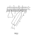
- the bottles 1 tend to oscillate back and forth around their vertical equilibrium position, in their direction of transport, according to a tilting angle referenced B in this figure.
- the maximum value of this angle B can for example advantageously be adjusted using longitudinal guides 7 (FIG. 1), which are positioned on either side of the bottle transport path, at the level of the tightening portion 1 b bottles, and whose spacing E is adjustable.
- the spacing E of the longitudinal guides 7, the maximum tilting angle forwards or backwards B of the bottles 1 is advantageously adjusted in their direction of transport.
- the two longitudinal guides 7 are adjusted in position so that the angle B is less than or equal to 30 °, which makes it possible to effectively limit the risks of blockage of a bottle 1 by tilting forward or backward in progress transport.
- the two guides 7 are preferably adjusted in position so that this angle B is greater than or equal to 10 °. It has been demonstrated that below a value of 10 ° for the tilting angle B, the bottles tended in a manner detrimental to their good conveying to be transported by oscillating in a jerky and too fast manner around their equilibrium position.
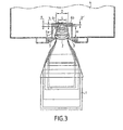
- the wedge 6 has been improved in that it has a longitudinal central recess 6 b in its lower face 6 a forming a longitudinal central channel.
- the width L of the recess 6 b is strictly less than the diameter D of the upper end 1 d of the bottle. This characteristic allows the lower face 6 a of the wedge 6 to fulfill its function of upper stop, in particular in the bottle accumulation phase, when a bottle 1 rises in vertical position relative to the guide rails 3.
- the part central hollowed out 6 b of the wedge 6 advantageously allows the front or rear tilting of the bottle 1 by an angle B, so that a portion of the end 1 d of the bottle rises in the channel formed by the recess 6 b , without coming into contact with the shim 6. Thanks to the structure of the shim 6 in FIG.
- the geometry of the recess 6 b (that is to say mainly the width L of the recess 6 b and its height h ) such so that there is a residual clearance Jr '( Figure 3) between the bottom wall 6 c of the recess 6 b and the upper end 1 d of a bottle 1 supported by the under-neck guides 3 at a given front or rear swing angle B.
- the geometry of the recess 6b will be chosen so that there is a residual clearance Jr 'when the bottle 1 is tilted at a tilting angle B front or rear equal to 45 °.
- blowing channel 5 of which has an upper wall 5 a in which a channel is provided longitudinal equivalent and fulfilling the same function as the central recess 6 b of the wedge 6.
- the height of the blowing channel is provided sufficiently low so that the underside of the wall 5 a , on either side of the central channel of this wall, fulfills the function of upper stop.
- an attached shim 6 which is not a solid shim in the thickness of which an obviously has been produced, but which is for example a sheet, shaped so to have a re-entrant channel fulfilling the same function as the central recess 6 b .
- an added shim 6 of thickness e calculated advantageously makes it possible to easily adapt the existing conveyors to a given type of bottles by judiciously choosing the thickness of the shim, in order to reduce the risks of blockage of the bottles. in the event of the bottles rising relative to the guide rails 3 of the conveyor.
- the geometry of the central recess 6 b of the wedge 6 is in the form of an inverted U, the side walls of the U being substantially orthogonal to the bottom 6 c of the recess. This geometry is not, however, limiting of the invention.
- the central recess 6 b could have any curved geometric shape, and for example in an arc of a circle, with a radius of curvature adapted to the radius of curvature of the upper end 1 d of the bottles 1.
- the wedge 6 of the variant in Figure 1 shows in this example a cross section of rectangular shape.
- the invention is of course not limited to this particular form of wedge 6, the cross section of the wedge 6 can be arbitrary, knowing that it suffices that there is a contact generator between the bottle and the wedge.
- the wedge 6 in the variant of Figure 1 could for example have a cylindrical, or semi-cylindrical cross section.
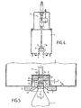
- FIG. 4 Another improved alternative embodiment of the invention has been illustrated in FIG. 4, in which the conveyor 4 is equipped with a longitudinal wedge 6, of small thickness, the height position of which is adjustable.
- the wedge 6 can be adjusted in height between two high and low positions, by means of a pneumatic cylinder 8 with two positions.
- the high position as illustrated in solid lines in FIG. 4, the shim 6 comes, for example, into contact with the upper wall 5 a of the blowing channel 5.
- the residual clearance existing between the bottles 1 and the wedge 6 is maximum; the bottles 1 can be transported freely without their upper end 1 d coming into contact with the wedge 6.
- the low position (as illustrated for example by dotted lines in FIG. 4), the residual clearance between the bottles and the wedge 6 is set to a minimum value.
- the air conveyor will be cut into a plurality of successive sections, each section comprising a wedge 6, the height of which can be adjusted independently with respect to the wedges 6 of the other sections.
- the sections of the conveyor in which the bottles are in the transport phase will be configured so that their wedge 6 is adjusted in the high position.
- the shims 6 of these sections will advantageously be adjusted in the low position, in order to reduce the risks of blockage of the accumulated bottles.
- the control of the jacks 8 associated with each wedge 6 can be automated from detection signals emitted by non-contact sensors of the photoelectric cell type or ultrasonic sensors, positioned respectively at each section, and allowing the automatic detection of an accumulation of bottles in a given section.
- the lower position of the wedge 6 of Figure 4 corresponds to the level of the lower face 6 a of the wedge 6 of Figure 3, and the position high corresponds to the level of the bottom 6 c of the longitudinal central recess 6 b of the wedge 6 of FIG. 3.
- the shim 6 can take several positions.
- This unlocking position is fixed according to the geometry of the bottles 1 so that in this position the wedge 6 is close enough to the under-neck guides 3 to allow the unlocking of a bottle 1 accidentally immobilized for example tilted forward or backward.
- the upper stop further comprises a longitudinal plate 6 d , which is housed in the obviously longitudinal 6 b of the wedge 6, and which is movable in translation in a vertical plane so that it can be adjusted in height. More particularly, the height position of this plate 6 d can be adjusted by means of a jack 8 'with two positions, between a high position (illustrated in solid lines) in which the plate 6 d is close to the bottom 6 c of the longitudinal course 6 b . This high position corresponds to the high position of the wedge 6 of the variant of FIG. 4. The low position (illustrated in dotted lines) corresponds to a position for unlocking the bottles 1.
- This position for unlocking the plate 6 d is located at an intermediate level between on the one hand the lower face 6 a of the wedge 6 and the upper end 1 d of a bottle 1 supported by the under-neck guides 3 in a vertical position.
- the plate 6 d when it is in the unlocked position, it is located at a distance H ′ with respect to the upper face 3 has under-neck guides 3 which is comprised on the one hand between the height H and on the other hand the height H b corresponding to the height of the upper part of the bottle 1, commonly called a drink, which extends between the upper end 1 d of the bottle 1 and collar 2 (including collar).
- the height H ′ will be provided slightly greater than the height H b .
- the height H ′ corresponding to the unlocking position of the plate 6 d must preferably be strictly greater than the height H b of the bottles 1, in order to avoid during unlocking operations a contact tightening the bottles 1 between plate 6 d and the under-neck guides 3.
Landscapes
- Physics & Mathematics (AREA)
- Engineering & Computer Science (AREA)
- Fluid Mechanics (AREA)
- Mechanical Engineering (AREA)
- Framework For Endless Conveyors (AREA)
- Attitude Control For Articles On Conveyors (AREA)
- Filling Of Jars Or Cans And Processes For Cleaning And Sealing Jars (AREA)
Description
La présente invention concerne le convoyage d'articles comportant une collerette ou similaire, formant protubérance, et permettant leur suspension en cours de transport. Elle a plus particulièrement pour objet un convoyeur dans lequel les articles sont transportés en étant suspendus par l'intermédiaire de leur collerette sur deux guides sous-col faisant office de rails de guidage, et en étant plus particulièrement propulsés les uns derrière les autres au moyen d'un flux d'air. Elle trouve principalement son application au transport d'articles légers en plastique, tels que des récipients (flacons ou bouteilles, etc...) en PET, PVC, etc..., notamment lors des opérations de conditionnement de ces articles, le convoyeur étant par exemple utilisé pour acheminer en ligne des récipients vides depuis une machine amont de fabrication de ces récipients (souffleuse) jusqu'à une machine aval de remplissage des récipients (soutireuse).The present invention relates to the conveyance of articles comprising a collar or the like, forming a protuberance, and allowing their suspension during transport. It has more particularly for object a conveyor in which the articles are transported while hanging via their flange on two under-neck guides serving guide rails, and being more particularly propelled each behind the others by means of an air flow. It mainly finds its application to the transport of light plastic articles, such as containers (flasks or bottles, etc.) made of PET, PVC, etc., in particular during the packaging operations of these articles, the conveyor being for example used to ship empty containers online from an upstream machine for manufacturing these containers (blower) up to a downstream machine for filling containers (filling machine).
Dans le domaine de l'embouteillage, il est à ce jour largement répandu d'utiliser des convoyeurs pneumatiques dans lesquels des bouteilles vides, ou d'une manière plus générale des articles, sont guidés les uns derrière les autres entre deux guides sous-col en étant supportés, par l'intermédiaire d'une protubérance (collerette) de leur col. Les articles sont mis en mouvement unitairement les uns derrière les autres ou par trains entiers de bouteilles, sous l'action de jets d'air. De tels convoyeurs ont par exemple déjà été décrits dans la demande de brevet internationale WO90/10587, et dans la demande de brevet anglais GB.2.092.981. Dans ces deux publications, les jets d'air de transport sont principalement dirigés sur le col des articles au-dessus de leur collerette. Dans d'autres types de convoyeurs connus, les jets d'air de transport peuvent également être dirigés sur le corps des articles au-dessous du niveau de la collerette. To date, in the bottling industry, widespread use of pneumatic conveyors in which empty bottles, or more generally items, are guided one behind the other between two under-neck guides while being supported, via a protrusion (collar) of their neck. The articles are set in motion one behind the other or by whole trains of bottles, under the action of air jets. Such conveyors have for example already been described in the international patent application WO90 / 10587, and in the English patent application GB.2.092.981. In these two publications, the transport air jets are mainly directed on the neck of the articles above their collar. In other known types of conveyors, transport air jets can also be directed onto the body of the articles below the level of the collar.
Au cours de leur transport, les articles qui sont supportés uniquement par leur collerette, ont tendance à basculer par rapport à la verticale. Le basculement des récipients par rapport à la verticale dans une direction transversale à leur direction de transport nuit à leur convoyabilité et occasionne en outre des risques de décrochements ou de coincement des articles. Il a donc à ce jour été proposé de limiter ce basculement dans une direction transversale à la direction de transport en équipant les convoyeurs de guide latéraux positionnés de part et d'autre du chemin de transport des articles. En pratique ces guides latéraux sont positionnés au niveau d'une portion cylindrique du corps des articles, en étant écartés l'un de l'autre d'une distance légèrement supérieure au diamètre de cette portion cylindrique. Les articles sont donc supportés par leur collerette et maintenus essentiellement verticalement au cours de leur transport dans un plan vertical transversal à leur direction de transport au moyen de ces guides. Les guides précités ne sont toutefois pas suffisants pour obtenir un bon convoyage des articles. En particulier, ces guides ne permettent pas d'éviter un blocage des articles au cours de leur transport.During their transport, the articles which are supported only by their flange, tend to tilt relative to the vertical. The tilting of the containers with respect to the vertical in a direction transverse to their direction of transport harms their conveyability and also poses risks of dropouts or jamming of articles. To date, it has therefore been proposed to limit this tilting in a direction transverse to the direction of transport in equipping the lateral guide conveyors positioned on both sides the transportation path of the items. In practice these lateral guides are positioned at a cylindrical portion of the body of the articles, in being spaced from each other by a distance slightly greater than the diameter of this cylindrical portion. The articles are therefore supported by their flange and held essentially vertically during their transport in a vertical plane transverse to their direction of transport at using these guides. The above guides are not sufficient, however. to obtain a good conveying of the articles. In particular, these guides do not do not prevent items from being blocked during transport.
En pratique, les blocages des articles en cours de transport apparaissent le plus fréquemment en phase d'accumulation des articles, c'est-à-dire dans une phase au cours de laquelle les articles forment un train statique ou en déplacement à très faible vitesse, les articles étant au contact et comprimés les uns contre les autres.In practice, blockages of items during transport most frequently appear during the accumulation of articles, that is to say in a phase during which the articles form a static train or moving at very low speed, the articles being contact and tablets against each other.
Ces blocages des articles en phase d'accumulation ont plusieurs causes. D'une manière générale, les articles étant comprimés les uns contre les autres, ils exercent une poussée qui tend à les faire remonter verticalement par rapport aux guides sous-col. Il peut arriver dans ce cas qu'au moins un des articles, du fait de cette remontée verticale, vienne se bloquer en position par serrage entre les guides sous-col. Il arrive également lorsque les articles ont un profil qui contribue à leur emboítement ou encastrement les uns par rapport aux autres, qu'en cas de remontée verticale, les articles se bloquent les uns par rapport aux autres, sans nécessairement se bloquer par serrage entre les guides sous-col. Il a également été constaté que les risques de blocage étaient plus fréquents lors du transport d'articles en plastique, et notamment de bouteilles en PET, issues directement d'une souffleuse. Ceci peut s'expliquer par le fait que la résine thermoplastique constitutive des parois des articles en plastique issus de la souffleuse est dans un état tel que les parois de ces articles sont collantes, et qu'un simple frottement d'un article l'un par rapport à l'autre lors de la remontée des articles, aboutit au collage des articles entre eux. Une autre cause de blocage des articles en phase d'accumulation est liée au fait qu'un article arrivant avec une vitesse importante au contact d'un train d'articles accumulés, a tendance à basculer de manière importante par rapport à la direction de transport en prenant appui sur le dernier article du train accumulé. L'article suivant vient alors, en appui contre la base de cet article incliné dans la direction de transport, et exerce sur celui-ci une poussée mécanique qui tend à le faire remonter entre les guides sous-col et à le bloquer en position inclinée.These blockages of articles in the accumulation phase have several causes. Generally, the articles being compressed together against the others, they exert a push which tends to make them go up vertically with respect to the under-neck guides. It can happen in this case that at least one of the articles, due to this vertical rise, comes lock in position by clamping between the under-neck guides. He is coming also when the articles have a profile which contributes to their nesting or embedding with respect to each other, only in case vertical ascent, the articles are blocked relative to the others, without necessarily locking by clamping between the under-neck guides. It was also found that the risks of blocking were more frequent when transporting plastic items, especially PET bottles, straight from a blower. This can can be explained by the fact that the thermoplastic resin constituting the walls plastic items from the snowblower are in such a condition that walls of these items are sticky, and that just rubbing a article in relation to each other when raising the articles, results in bonding of the articles between them. Another cause of blockage of articles in accumulation phase is linked to the fact that an item arriving with a high speed in contact with a train of accumulated articles, tends to tilt significantly compared to the transport direction in building on the last item of the accumulated train. The following article then comes to rest against the base of this article inclined in the direction transport, and exerts on it a mechanical thrust which tends to bring it up between the under-neck guides and lock it in position inclined.
Il a déjà été proposé dans le brevet US.5,421,678 d'équiper un convoyeur à air de guides-épaules supérieurs (référencés 42 sur les figures 4, 7 et 8 de ce document), dont la fonction principale est de faire office de butée en cas de remontée des articles. Cette solution présente toutefois les deux inconvénients majeurs suivants. Avec cette solution, on réduit certes le problème de blocage des récipients entre les guides sous-col, mais on fait apparaítre un nouveau risque de blocage des récipients entre les guides-épaules, en particulier lors de la remontée des récipients en phase d'accumulation. Cette solution n'est donc pas satisfaisante au regard du problème de blocage des articles en phase d'accumulation. L'autre inconvénient de cette solution est lié au problème de la détermination du réglage optimal de l'écartement des guides-épaules l'un par rapport à l'autre. En effet, en agissant sur l'écartement entre les guides-épaules, on autorise plus ou moins la remontée des articles ; en pratique plus les guides-épaules sont proches l'un de l'autre, meilleur est le blocage vertical des articles. Néanmoins, en agissant sur l'écartement des guides-épaules l'un par rapport à l'autre, on agit également sur l'angle de basculement avant ou arrière dans un plan vertical des articles dans leur direction de transport ; en pratique, plus l'écartement des guides-épaules est faible, et plus l'angle de basculement des articles est limité. Or il est connu qu'un angle de basculement trop important des articles au cours de leur transport peut occasionner un blocage avant ou arrière des articles par rapport aux guides sous-col, mais qu'il est toutefois nécessaire que les articles en cours de transport puissent osciller légèrement par rapport à la verticale dans leur direction de transport d'un angle de basculement minimum afin d'obtenir une meilleur convoyabilité des articles. Avec la solution de guides épaules supérieurs du brevet US.5,421,678, on est donc obligé de choisir un réglage de l'écartement des guides-épaules en fonction de deux contraintes : assurer une butée efficace à la remontée des articles et obtenir une bonne limitation de l'angle de basculement avant ou arrière des articles au cours de leur transport. Ces deux contraintes rendent difficile le choix du réglage de l'écartement optimum des guides-épaules.It has already been proposed in US patent 5,421,678 to equip a air conveyor of upper shoulder guides (referenced 42 on the Figures 4, 7 and 8 of this document), the main function of which is to make abutment office in the event of an ascent of the articles. This solution presents however the following two major drawbacks. With this solution, we certainly reduces the problem of blocking of the containers between the under-neck guides, but there is a new risk of container blockage appearing between the shoulder guides, especially when raising the containers in the accumulation phase. This solution is therefore not satisfactory look at the problem of blocking items in the accumulation phase. The other drawback of this solution is related to the problem of determination of the optimal adjustment of the spacing of the shoulder guides one compared to each other. Indeed, by acting on the spacing between the shoulder guides, the articles are more or less authorized; in the closer the shoulder guides are to each other, the better vertical blocking of articles. However, by acting on the spacing shoulder guides relative to each other, we also act on the angle tilting forward or backward in a vertical plane of the articles in their direction of transport; in practice, the greater the spacing of the shoulder guides is low, and the more the tilting angle of the articles is limited. Gold it is known that an excessive tilting angle of the articles at the during their transport can cause a front or rear blockage of the articles compared to under-neck guides but that it is however necessary that the items in transport may oscillate slightly by relation to the vertical in their direction of transport of an angle of minimum tilting in order to obtain better conveyability of items. With the patent upper shoulder guide solution US 5,421,678, so we have to choose a spacing adjustment shoulder guides according to two constraints: ensuring a stop effective at raising the articles and obtaining good limitation of the tilt angle of the articles before or back during their transport. These two constraints make it difficult to choose the adjustment of the optimum spacing of the shoulder guides.
La présente invention propose une nouvelle solution permettant de
réduire les risques de blocage des articles, en particulier en phase
d'accumulation, tout en palliant les deux inconvénients précités inhérents
à la mise en oeuvre de guides-épaules supérieurs à fonction de butée telle
qu'elle est enseignée dans le brevet US.5,421,678. Cette solution est
obtenue grâce au convoyeur de la revendication 1.The present invention provides a new solution for
reduce the risk of blocking items, especially in phase
accumulation, while overcoming the two aforementioned inherent drawbacks
the implementation of upper shoulder guides with stop function such
that it is taught in patent US 5,421,678. This solution is
obtained by the conveyor of
Des variantes de réalisation de l'invention apparaítront plus clairement à la lecture de la description ci-après laquelle description est donnée à titre d'exemple non limitatif et en référence au dessin annexé sur lequel :
- la figure 1 est une coupe transversale schématique d'une variante simplifiée non revendiquée d'un convoyeur à air selon l'invention, utilisé pour le transport de bouteilles, et mettant en oeuvre en guise de butée haute une cale rapportée d'épaisseur constante,
- la figure 2 schématise le jeu résiduel (Jr') existant entre la cale à fonction de butée haute et l'extrémité supérieure du col d'une bouteille inclinée d'un angle de basculement (B) par rapport à la verticale et dans la direction de transport,
- la figure 3 est une coupe transversale de principe d'une première variante perfectionnée d'un convoyeur à air de l'invention mettant en oeuvre une cale avec un évidement central formant un canal longitudinal,
- la figure 4 est une vue de principe d'une deuxième variante perfectionnée de réalisation d'un convoyeur à air selon l'invention, mettant en oeuvre une butée haute à hauteur réglable,
- et la figure 5 est une coupe de principe d'une troisième variante perfectionnée de réalisation d'un convoyeur à air selon l'invention, mettant en oeuvre une cale évidée avec plaque mobile à hauteur réglable.
- FIG. 1 is a schematic cross-section of a simplified unclaimed variant of an air conveyor according to the invention, used for the transport of bottles, and using as a top stop an added shim of constant thickness,
- Figure 2 shows schematically the residual clearance (Jr ') existing between the block with high stop function and the upper end of the neck of a bottle inclined at a tilting angle (B) relative to the vertical and in the direction transport,
- FIG. 3 is a cross-section in principle of a first improved variant of an air conveyor of the invention using a block with a central recess forming a longitudinal channel,
- FIG. 4 is a view in principle of a second improved alternative embodiment of an air conveyor according to the invention, using a high stop with adjustable height,
- and FIG. 5 is a cross-section in principle of a third improved variant embodiment of an air conveyor according to the invention, using a recessed wedge with a movable plate with adjustable height.
Le convoyeur illustré schématiquement à la figure 1 est utilisé pour
transporter, par voie pneumatique, des bouteilles 1 en ligne les unes
derrière les autres. Chaque bouteille 1 comporte un col 1a,
correspondant au goulot de la bouteille, qui dans l'exemple particulier
illustré est sensiblement cylindrique de diamètre d, et est pourvu au
niveau de son col 1a d'une collerette 2 externe formant protubérance.
Chaque bouteille 1 comprend en outre un corps principal 1c de forme
sensiblement cylindrique, se prolongeant par une portion de
resserrement 1b qui s'étend jusqu'au col 1a et dont la section décroít
en direction de la collerette 2. Les bouteilles 1 sont transportées en
étant suspendues sur deux rails de guidage 3, plus communément
appelés guides sous-col. Dans l'exemple particulier illustré à la figure 1,
le convoyeur comprend un caisson de soufflage 4, ayant une section
sensiblement rectangulaire, et alimenté de manière usuelle avec de l'air
sous pression qui a de préférence été préalablement filtré. A l'intérieur
du caisson de soufflage 4 est aménagé un canal de soufflage 5 de plus
faible section en forme de U renversé et délimité par une paroi
supérieure 5a et deux parois latérales 5b. Le canal de soufflage 5
communique avec le caisson de soufflage 4 par l'intermédiaire de fentes
5c aménagées dans les parois latérales 5b et réparties judicieusement
sur toute la longueur du canal de soufflage 5. L'air sous pression à
l'intérieur du caisson 4 pénètre à l'intérieur du canal de soufflage 5 en
étant dirigé sur les bouteilles 1 au-dessus de leur collerette 2, et
entraíne par là-même les bouteilles les unes derrière les autres dans
une direction transversale au plan de la figure 1, les bouteilles 1 étant
guidées et supportées au cours de leur transport par les guides sous-col
3. Dans une autre variante de réalisation, l'air de transport pourrait
également être soufflé en direction du corps des bouteilles, au-dessous
de leur collerette 2, en étant par exemple canalisé entre deux parois
latérales verticales situées de part et d'autre du chemin de transport
des bouteilles.The conveyor illustrated schematically in Figure 1 is used to transport, pneumatically,
Dans la variante de la figure 1, le convoyeur est équipé d'une cale
longitudinale rapportée 6, d'épaisseur constante e. Cette cale 6 est
fixée par tout moyen approprié connu sur la face intérieure de la paroi
supérieure 5a du canal de soufflage 5. Cette cale 6 s'étend
longitudinalement sur toute la longueur du canal de soufflage 5. Cette
cale 6 fait office de butée haute et permet de limiter la remontée des
bouteilles entre les guides sous-col 3. Le choix de l'épaisseur e de la
cale 6 permet de fixer la distance H séparant la face inférieure 6a de la
cale 6 à fonction de butée haute, de la face supérieure 3a des guides
sous-col 3, et par là-même de régler la hauteur de la butée haute en
fonction des articles à transporter. De préférence, l'épaisseur e de la
cale 6 (c'est-à-dire en d'autres termes la distance H) est fixée de telle
sorte qu'il existe, entre la face inférieure 6a de la cale 6 et l'extrémité
supérieure 1d d'une bouteille supportée en position verticale par les
guides sous-col 3 (figure 1), un jeu résiduel Jr qui est strictement
inférieur à la hauteur de contact Hc, c'est-à-dire à la distance séparant
les guides sous-col 3 et la section de contact Sc de la bouteille. Cette
section de contact Sc correspond à la section droite de la portion de
resserrement 1b de la bouteille dont le diamètre est égal à l'écartement
Eg des guides sous-col 3. Grâce à cette caractéristique, on évite ainsi
avantageusement, en cas de remontée de la bouteille 1 en position
verticale entre les guides sous-col 3, que la section de contact Sc
n'atteigne les guides sous-col 3, ce qui permet par là-même d'éviter un
blocage en position verticale de la bouteille par serrage entre les deux
guides sous-col 3. D'une manière plus générale, la cale 6 permet en
limitant la remontée d'une bouteille 1, de réduire les risques de blocage
des bouteilles 1 en phase d'accumulation lorsque les bouteilles
remontent les unes par rapport aux autres sous l'effet de compression
qu'elles exercent les unes sur les autres, ou lorsque les bouteilles
remontent en basculant en phase d'accostage.In the variant of FIG. 1, the conveyor is equipped with an attached
On comprend qu'en phase d'accumulation des bouteilles 1,
l'efficacité de la cale 6 à fonction de butée haute est d'autant meilleure
que le jeu résiduel Jr (figure 1) est faible. Dans la variante de la figure
1, ce jeu Jr doit toutefois être prévu suffisamment important pour ne
pas perturber le mouvement des bouteilles 1 au cours de leur transport
tel que cela apparaítre plus clairement à la lumière de la figure 2.We understand that in the accumulation phase of the
Si l'on se réfère à la figure 2, au cours de leur transport, les
bouteilles 1 ont tendance à osciller en avant et en arrière autour de leur
position d'équilibre vertical, dans leur direction de transport, selon un
angle de basculement référencé B sur cette figure. La valeur maximale
de cet angle B peut par exemple avantageusement être réglée à l'aide
guides longitudinaux 7 (figure 1), qui sont positionnés de part et d'autre
du chemin de transport des bouteilles, au niveau de la portion de
resserrement 1b des bouteilles, et dont l'écartement E est réglable. En
réglant l'écartement E des guides longitudinaux 7, on règle
avantageusement l'angle maximum de basculement avant ou arrière B
des bouteilles 1 dans leur direction de transport. De préférence, les
deux guides longitudinaux 7 sont réglés en position de telle sorte que
l'angle B soit inférieur ou égal à 30°, ce qui permet de limiter
efficacement les risques de blocage d'une bouteille 1 par basculement
avant ou arrière en cours de transport. En outre, les deux guides 7 sont
de préférence réglés en position de telle sorte que cet angle B soit
supérieur ou égal à 10°. Il a été mis en évidence qu'en deçà d'une
valeur de 10° pour l'angle de basculement B, les bouteilles avaient
tendance de manière préjudiciable à leur bon convoyage à être
transportées en oscillant de manière saccadée et trop rapide autour de
leur position d'équilibre.Referring to FIG. 2, during their transport, the
Lorsqu'une bouteille 1 bascule en avant ou en arrière dans sa
direction de transport d'un angle B, une portion de son extrémité
supérieure 1d remonte du fait de ce basculement, tel que cela apparaít
sur la figure 2. Pour éviter de perturber le déplacement des bouteilles 1,
il est donc essentiel qu'en cas de basculement d'une bouteille 1 d'un
angle B, l'extrémité 1d ne vienne pas au contact de la face inférieure 6a
de la cale 6, ce qui est matérialisé sur la figure 2 par un jeu résiduel Jr'.
De préférence, sachant que la remontée de l'extrémité 1d de la
bouteille 1 est maximale lorsque l'angle de basculement B avant ou
arrière de la bouteille 1 vaut 45°, l'épaisseur de la cale sera choisie de
telle sorte qu'il existe un jeu résiduel Jr' en cas de basculement de la
bouteille d'un angle B valant 45°.When a
Dans la variante de la figure 3, la cale 6 a été perfectionnée en ce
qu'elle présente un évidement central longitudinal 6b dans sa face
inférieure 6a formant un canal central longitudinal. De manière
essentielle selon l'invention, la largeur L de l'évidement 6b est
strictement inférieure au diamètre D de l'extrémité supérieure 1d de la
bouteille. Cette caractéristique permet à la face inférieure 6a de la cale
6 de remplir sa fonction de butée haute, en particulier en phase
d'accumulation des bouteilles, lorsqu'une bouteille 1 remonte en
position verticale par rapport aux rails de guidage 3. La partie centrale
évidée 6b de la cale 6 permet avantageusement le basculement avant
ou arrière de la bouteille 1 d'un angle B, de telle sorte qu'une portion
de l'extrémité 1d de la bouteille remonte dans le canal formé par
l'évidement 6b, sans venir au contact de la cale 6. Grâce à la structure
de la cale 6 de la figure 3, il est donc avantageusement possible de
choisir d'une part une épaisseur e de cale en sorte d'obtenir un jeu
résiduel Jr faible lorsque la bouteille 1 est en position verticale et
d'autre part d'adapter la géométrie de l'évidement 6b (c'est-à-dire
principalement la largeur L de l'évidement 6b et sa hauteur h) de telle
sorte qu'il existe un jeu résiduel Jr' (figure 3) entre la paroi de fond 6c
de l'évidement 6b et l'extrémité supérieure 1d d'une bouteille 1
supportée par les guides sous-col 3 selon un angle de balancement
avant ou arrière B donné. De préférence, la géométrie de l'évidement
6b sera choisie de telle sorte qu'il existe un jeu résiduel Jr' lorsque la
bouteille 1 est inclinée selon un angle de basculement B avant ou
arrière valant 45°.In the variant of FIG. 3, the
Dans le cadre de cette variante de la figure 3, il est envisageable de
ne pas mettre en oeuvre une cale rapportée, mais de concevoir
d'emblée un convoyeur dont le canal de soufflage 5 comporte une paroi
supérieure 5a dans laquelle est prévu un canal longitudinal équivalent
et remplissant la même fonction que l'évidement central 6b de la cale 6.
Dans ce cas, la hauteur du canal de soufflage est prévue suffisamment
faible pour que la face inférieure de la paroi 5a, de part et d'autre du
canal central de cette paroi, remplisse la fonction de butée haute. Dans
une autre variante, il est également envisageable de mettre en oeuvre
une cale 6 rapportée qui n'est pas une cale pleine dans l'épaisseur de
laquelle a été réalisé un évidemment, mais qui est par exemple une
tôle, mise en forme en sorte de comporter un canal rentrant
remplissant la même fonction que l'évidement central 6b. Enfin, il est
également envisageable de mettre en oeuvre une cale rapportée formée
de deux éléments longitudinaux distincts, fixés sur la face interne de la
paroi supérieure 5a du canal de soufflage 5, en étant séparés l'un de
l'autre par un canal de longueur L remplissant la même fonction que
l'évidement central 6b de la cale 6 de la figure 3.In the context of this variant of FIG. 3, it is conceivable not to use an attached shim, but to immediately design a conveyor, the blowing
La mise en oeuvre d'une cale rapportée 6 d'épaisseur e calculée
permet avantageusement d'adapter de manière simple les convoyeurs
existants à un type donné de bouteilles en choisissant judicieusement
l'épaisseur de la cale, pour réduire les risques de blocage des bouteilles
en cas de remontée des bouteilles par rapport aux rails de guidage 3 du
convoyeur. Dans les exemples particuliers illustrés, la géométrie de
l'évidement central 6b de la cale 6 est en forme de U renversé, les
parois latérales du U étant sensiblement orthogonales au fond 6c de
l'évidemment. Cette géométrie n'est toutefois pas limitative de
l'invention. L'évidement central 6b pourrait avoir une forme
géométrique courbe quelconque, et par exemple en arc de cercle, avec
un rayon de courbure adapté au rayon de courbure de l'extrémité
supérieure 1d des bouteilles 1. Egalement la cale 6 de la variante de la
figure 1 présente dans cet exemple une section droite de forme
rectangulaire. L'invention n'est bien entendu pas limitée à cette forme
particulière de cale 6, la section droite de la cale 6 pouvant être
quelconque, sachant qu'il suffit qu'il y ait une génératrice de contact
entre la bouteille et la cale. La cale 6 dans la variante de la figure 1
pourrait par exemple présenter une section droite cylindrique, ou semi-cylindrique.The use of an added
On a illustré à la figure 4 une autre variante perfectionnée de
réalisation de l'invention, dans laquelle le convoyeur 4 est équipé d'une
cale 6 longitudinale, de faible épaisseur, dont la position en hauteur est
réglable. Dans l'exemple illustré, la cale 6 peut être réglée en hauteur
entre deux positions haute et basse, au moyen d'un vérin pneumatique
8 à deux positions. En position haute, telle qu'illustrée en traits pleins
sur la figure 4, la cale 6 vient par exemple au contact de la paroi
supérieure 5a du canal de soufflage 5. Dans cette position, le jeu
résiduel existant entre les bouteilles 1 et la cale 6 est maximum ; les
bouteilles 1 peuvent être transportées librement sans que leur
extrémité supérieure 1d ne vienne en contact avec la cale 6. En position
basse (telle qu'illustrée par exemple en pointillés sur la figure 4), le jeu
résiduel entre les bouteilles et la cale 6 est réglé à une valeur minimale.
En pratique, le convoyeur à air sera découpé en une pluralité de
tronçons successifs, chaque tronçon comportant une cale 6 dont la
hauteur peut être réglée de manière indépendante par rapport aux
cales 6 des autres tronçons. Les tronçons du convoyeur dans lesquels
les bouteilles sont en phase de transport seront configurés de telle
sorte que leur cale 6 est réglée en position haute. En revanche, dans
les tronçons de convoyeur correspondant à des zones d'accumulation
des bouteilles 1, on réglera avantageusement les cales 6 de ces
tronçons en position basse, afin de réduire les risques de blocage des
bouteilles en accumulation. La commande des vérins 8 associés à
chaque cale 6 pourra être automatisée à partir de signaux de détection
émis par des capteurs sans contact du type cellules photo-électriques
ou capteurs ultrasons, positionnés respectivement au niveau de chaque
tronçon, et permettant la détection automatique d'une accumulation de
bouteilles dans un tronçon donné.Another improved alternative embodiment of the invention has been illustrated in FIG. 4, in which the conveyor 4 is equipped with a
Si l'on compare la variante de la figure 4 à celle de la figure 3, la
position basse de la cale 6 de la figure 4 correspond au niveau de la
face inférieure 6a de la cale 6 de la figure 3, et la position haute
correspond au niveau du fond 6c de l'évidement central longitudinal 6b
de la cale 6 de la figure 3.If we compare the variant of Figure 4 to that of Figure 3, the lower position of the
Dans une autre variante de réalisation, il est envisageable de
modifier la variante de la figure 4 de telle sorte que la cale 6 puisse
prendre plusieurs positions. En particulier, dans une variante
perfectionnée, il est possible de prévoir, en mettant par exemple en
oeuvre un vérin pneumatique 8 à trois positions, une position
supplémentaire pour la cale 6, située au-dessous du niveau de la
position basse de la figure 4 et correspondant à une position dite de
déblocage. Cette position de déblocage est fixée en fonction de la
géométrie des bouteilles 1 de telle sorte que dans cette position la cale
6 est suffisamment proche des guides sous-col 3 pour permettre le
déblocage d'une bouteille 1 immobilisée accidentellement par exemple
en position inclinée vers l'avant ou l'arrière.In another alternative embodiment, it is possible to envisage
modify the variant of figure 4 so that the
Dans la variante de la figure 5, on retrouve la cale 6 avec
évidement central de la variante de la figure 3. Dans cette variante de
la figure 5, la butée haute comprend en outre une plaque longitudinale
6d, qui est logée dans l'évidemment longitudinal 6b de la cale 6, et qui
est mobile en translation dans un plan vertical en sorte de pouvoir être
réglée en hauteur. Plus particulièrement, la position en hauteur de cette
plaque 6d peut être réglée au moyen d'un vérin 8' à deux positions,
entre une position haute (illustrée en traits pleins) dans laquelle la
plaque 6d est proche du fond 6c de l'évidemment longitudinal 6b. Cette
position haute correspond à la position haute de la cale 6 de la variante
de la figure 4. La position basse (illustrée en pointillés) correspond à
une position de déblocage des bouteilles 1. Cette position de déblocage
de la plaque 6d est située à un niveau intermédiaire entre d'une part la
face inférieure 6a de la cale 6 et l'extrémité supérieure 1d d'une
bouteille 1 supportée par les guides sous-col 3 en position verticale. En
d'autres termes, si l'on se réfère à la figure 5, lorsque la plaque 6d est
en position de déblocage, elle se situe à une distance H' par rapport à
la face supérieure 3a des guides sous-col 3 qui est comprise d'une part
entre la hauteur H et d'autre part la hauteur Hb correspondant à la
hauteur de la partie supérieure de la bouteille 1, communément
appelée buvant, qui s'étend entre l'extrémité supérieure 1d de la
bouteille 1 et la collerette 2 (collerette comprise). De préférence, la
hauteur H' sera prévue légèrement supérieure à la hauteur Hb. Il faut
ici souligner que la hauteur H' correspondant à la position de déblocage
de la plaque 6d doit de préférence être strictement supérieure à la
hauteur Hb des bouteilles 1, afin d'éviter lors des opérations de
déblocage un contact serrant des bouteilles 1 entre la plaque 6d et les
guides sous-col 3.In the variant of Figure 5, there is the
Claims (12)
- An air conveyor for articles each provided with an outwardly-projecting collar (2), said conveyor having two spaced-apart under-neck guides (3) along which the articles are to be transported by being suspended on the under-neck guides (3) via their collars (2), the conveyor being characterized in that it includes a longitudinal stop (6) above the under-neck guides (3), said stop serving to limit the up stroke available to articles between the under-neck guides (3), and comprising a longitudinal central channel (6b).
- A conveyor according to claim 1, for articles including a tapering portion (1b) beneath the collar (2), with the section of the tapering portion decreasing towards the collar and passing through a "contact" section (Sc) of diameter equal to the spacing (Eg) between the under-neck guides (3), the conveyor being characterized in that the stop (6) is provided at a distance (H) from the under-neck guides (3) such that residual clearance (Jr) exists between the stop (6) and the top end of an article when supported in the vertical position by the under-neck guides (3), which residual clearance (Jr) is less than the "contact" height (Hc) between the under-neck guides (3) and the contact section (Sc) of the article when in the vertical position.
- A conveyor according to claim 1 or 2, characterized in that the width (L) of the channel (6b) is less than the diameter (D) of an article at its top end (1d).
- A conveyor according to any one of claims 1 to 3, characterized in that the shape of the channel (6b) is designed in such a manner as to ensure that residual clearance (Jr') exists between the stop (6) and the top end of an article supported by the under-neck guides (3) when the article is at a forward or backward tilt angle of 45°.
- A conveyor according to any one of claims 1 to 4, characterized in that it includes a longitudinal plate (6d) mounted in register with the central channel (6b) and having a vertical position that is adjustable.
- A conveyor according to claim 5, characterized in that the plate (6d) is designed to be adjusted vertically to occupy at least two positions :a high position in which the plate (6d) is received in the central channel (6b),a low position for unjamming articles, in which position the plate (6d) is situated beneath the level of the bottom face (6a) of the stop (6) that serves as an abutment.
- A conveyor according to any one of claims 1 to 6, characterized in that the stop (6) is constituted by a add-on block.
- A conveyor according to any one of claims 1 to 6, comprising a blowing channel (5) and characterized in that the stop (6) is constituted by the top wall (5a) of the blowing channel (5).
- Conveyor according to any one of claims 1 to 8, characterized in that the stop (6) is constituted by a metal sheet shaped so as to have a reentrant channel.
- Conveyor according to claims 1 to 7, characterized in that the stop (6) is constituted by two separate longitudinal elements that are spaced apart from each other by the central longitudinal channel (6b).
- A conveyor according to any one claims 1 to 10, characterized in that it further comprises two top longitudinal guides (7) which are positioned on either side of the path of the articles and which serve to limit the forward or backward tilt angles (B) of the articles in a vertical plane and in their transport direction.
- A conveyor according to claim 11, characterized in that the two top guides (7) are adjusted in position in such a manner that the forward and backward tilt angles (B) of an article being transported are less than or equal to 30°, and preferably less than or equal to 25°, and are also greater than or equal to 10°.
Applications Claiming Priority (3)
| Application Number | Priority Date | Filing Date | Title |
|---|---|---|---|
| FR9710770 | 1997-08-25 | ||
| FR9710770A FR2767517B1 (en) | 1997-08-25 | 1997-08-25 | CONVEYOR FOR CONTAINERS WITH GUIDES FOR LIMITING TIPPING OF CONTAINERS WITH RESPECT TO THE VERTICAL IN THEIR DIRECTION OF TRANSPORT |
| EP98940335A EP1007456B1 (en) | 1997-08-25 | 1998-07-24 | Conveyor for transporting articles provided with a flange or the like |
Related Parent Applications (1)
| Application Number | Title | Priority Date | Filing Date |
|---|---|---|---|
| EP98940335A Division EP1007456B1 (en) | 1997-08-25 | 1998-07-24 | Conveyor for transporting articles provided with a flange or the like |
Publications (3)
| Publication Number | Publication Date |
|---|---|
| EP1207124A1 EP1207124A1 (en) | 2002-05-22 |
| EP1207124B1 true EP1207124B1 (en) | 2003-10-22 |
| EP1207124B2 EP1207124B2 (en) | 2009-09-16 |
Family
ID=9510576
Family Applications (2)
| Application Number | Title | Priority Date | Filing Date |
|---|---|---|---|
| EP98940335A Expired - Lifetime EP1007456B1 (en) | 1997-08-25 | 1998-07-24 | Conveyor for transporting articles provided with a flange or the like |
| EP01130946A Expired - Lifetime EP1207124B2 (en) | 1997-08-25 | 1998-07-24 | Conveyor for transporting articles provided with a flange or the like |
Family Applications Before (1)
| Application Number | Title | Priority Date | Filing Date |
|---|---|---|---|
| EP98940335A Expired - Lifetime EP1007456B1 (en) | 1997-08-25 | 1998-07-24 | Conveyor for transporting articles provided with a flange or the like |
Country Status (9)
| Country | Link |
|---|---|
| US (1) | US6488449B1 (en) |
| EP (2) | EP1007456B1 (en) |
| JP (1) | JP3983474B2 (en) |
| AU (1) | AU8868298A (en) |
| DE (4) | DE1207124T1 (en) |
| ES (2) | ES2210088T5 (en) |
| FR (1) | FR2767517B1 (en) |
| MX (1) | MXPA04002053A (en) |
| WO (1) | WO1999010263A1 (en) |
Families Citing this family (29)
| Publication number | Priority date | Publication date | Assignee | Title |
|---|---|---|---|---|
| IT1305257B1 (en) * | 1998-01-15 | 2001-04-19 | Sipa Spa | IMPROVED SYSTEM FOR SEQUENTIAL ORDER TRANSFER OF THERMOPLASTIC RESIN CONTAINERS. |
| IT1308585B1 (en) * | 1999-12-23 | 2002-01-08 | Lino Lanfranchi | APPARATUS FOR THE SUSPENDED TRANSPORT OF CONTAINERS PROVIDED WITH A COLLAR-RELEASE. |
| FR2806067A1 (en) | 2000-03-08 | 2001-09-14 | Netra Systems | Method for transporting plastic bottles comprises applying jet of air to bottles between two guide rails while they are supported during transport by inclined air jets from below directed against direction of transport of bottles |
| FR2806068A1 (en) | 2000-03-08 | 2001-09-14 | Netra Systems | Air jet transporting procedure and conveyor e.g. for plastic bottles uses lower jets to incline articles rearwards relative to direction of travel |
| DE20112256U1 (en) | 2001-07-25 | 2002-12-05 | KRONES AG, 93073 Neutraubling | air conveyor |
| JP4017898B2 (en) * | 2002-03-18 | 2007-12-05 | 東洋自動機株式会社 | Conveyor for spout or spouted bag |
| US20040170479A1 (en) * | 2002-04-16 | 2004-09-02 | Colin Huxley | Process and conveyor for transporting suspensed containers, installation and process for manufacturing and transporting containers |
| US6736573B1 (en) * | 2002-10-30 | 2004-05-18 | Goldco Industries, Inc. | Selective conveying of unstable articles having a neck ring |
| WO2004060780A1 (en) * | 2003-01-06 | 2004-07-22 | Awa Engineering Co.,Ltd | Device for taking out bar-like workpiece whose one end is large sized |
| FR2854152A1 (en) | 2003-04-25 | 2004-10-29 | Netra Systems | Adjustable positioning system for conveyor, has conveyor unit and jack assembled on adjustable support, where jack makes support to pivot and translate without modification of orientation of conveyor unit |
| WO2004096680A1 (en) | 2003-04-25 | 2004-11-11 | Netra Systems | Adjustable positioning system for a conveyor |
| DE102004055098A1 (en) * | 2004-11-15 | 2006-05-24 | Krones Ag | Behälterumgreifer |
| FR2890061A1 (en) * | 2005-08-29 | 2007-03-02 | Sidel Sas | Container loader for transporter has ejector for incorrectly loaded containers equipped with receiver synchronised with movement of gripper |
| FR2890062B1 (en) * | 2005-08-29 | 2008-10-31 | Sidel Sas | DEVICE FOR LOADING OR UNLOADING CONTAINERS COMPRISING A COLLAR ON A TRANSPORT MEMBER |
| DE102005043436B4 (en) * | 2005-09-13 | 2014-02-13 | Schaeffler Technologies AG & Co. KG | Wheel bearing unit for motor vehicles and method for producing the same |
| US7481606B2 (en) * | 2006-06-08 | 2009-01-27 | Freddy Robert Lyons | System, method, and apparatus for air-propelled conveyance of workpieces in sanitary environments |
| JP5135916B2 (en) * | 2007-06-29 | 2013-02-06 | 澁谷工業株式会社 | Air conveyor |
| JP2009035356A (en) * | 2007-07-31 | 2009-02-19 | Suntory Ltd | Bottle conveying apparatus and bottle conveying method |
| CH704401A1 (en) * | 2011-01-28 | 2012-07-31 | M Tanner Ag | Conveyor for cylindrical bodies, with inclined in conveying direction delivery rails. |
| DE102011056441A1 (en) * | 2011-12-14 | 2013-06-20 | Krones Ag | Device for transporting plastic preforms |
| CA2882922C (en) * | 2014-02-21 | 2020-12-01 | Septimatech Group Inc. | Guide rail system with cover element |
| FR3028254B1 (en) * | 2014-11-10 | 2019-04-12 | Sidel Participations | PROCESS FOR TRANSPORTING PREFORMS OF PLASTIC CONTAINERS |
| DE102015205984A1 (en) * | 2015-04-02 | 2016-10-06 | Krones Aktiengesellschaft | Method and guide system for the transport of containers or container components in industrial plants for container production and / or product filling |
| FR3051780A1 (en) * | 2016-05-25 | 2017-12-01 | Sidel Participations | METHOD FOR UNLOCKING THE HOLLOW BODY SCROLL IN A SLIDE CONVEYOR |
| US9884733B1 (en) * | 2017-08-11 | 2018-02-06 | Flexibility Engineering, Llc | Conveyed bottle guide apparatus and method |
| WO2020150413A1 (en) * | 2019-01-18 | 2020-07-23 | Société des Produits Nestlé S.A. | Systems, methods, and devices for unjamming a manufacturing line |
| FR3102702B1 (en) * | 2019-11-05 | 2021-11-05 | Sidel Participations | Method of guiding a straightened preform in a gap of a device for aligning and straightening preforms and associated alignment and straightening device |
| CN113264368B (en) * | 2021-06-16 | 2022-10-11 | 上海紫泉饮料工业有限公司 | Continuous conveying channel for preventing plastic bottles from being blocked |
| DE102023109658A1 (en) * | 2023-04-18 | 2024-10-24 | Krones Aktiengesellschaft | Device and method for transporting plastic preforms with fault elimination |
Citations (1)
| Publication number | Priority date | Publication date | Assignee | Title |
|---|---|---|---|---|
| WO1990010587A1 (en) * | 1989-03-08 | 1990-09-20 | Sarcmi S.P.A. | Conveyor belt with combined air nozzles |
Family Cites Families (26)
| Publication number | Priority date | Publication date | Assignee | Title |
|---|---|---|---|---|
| GB2092981B (en) * | 1981-02-14 | 1985-01-09 | Smith Dennis Claude | Air-bed conveyers |
| US4822214A (en) * | 1987-06-12 | 1989-04-18 | Aidlin Automation Corp. | Air conveyor |
| DE8807146U1 (en) * | 1988-06-01 | 1988-08-18 | Holstein Und Kappert Ag, 4600 Dortmund | Device for transporting bottles |
| NL9001589A (en) † | 1990-07-12 | 1992-02-03 | Smit Gerardus | TRANSPORTATION DEVICE FOR BOTTLES. |
| US5246314A (en) † | 1991-08-06 | 1993-09-21 | Simplimatic Engineering Company | Bottle air conveyor with adjustable guides |
| US5161919A (en) * | 1991-08-06 | 1992-11-10 | Simplimatic Engineering Company | Bottle air conveyor |
| US5248045A (en) * | 1991-12-12 | 1993-09-28 | The Coca-Cola Company | Method and apparatus for uncasing and sorting bottles |
| US5553080A (en) * | 1992-08-13 | 1996-09-03 | Nec Corporation | Speech decoding apparatus comprising alarm signal generator operable on deterioration of transmission path quality |
| US5484237A (en) * | 1992-12-29 | 1996-01-16 | Langenbeck; Keith A. | Pneumatic conveyor apparatus having air deflectors |
| US5437521A (en) * | 1993-05-13 | 1995-08-01 | Ouellette Machinery Systems, Inc. | Air conveyor for bottles |
| US5421678A (en) * | 1993-06-28 | 1995-06-06 | Aidlin; Samuel S. | Method and apparatus for conveying bottles |
| US5516239A (en) * | 1994-02-22 | 1996-05-14 | Pak Air, Inc. | Bottle conveyor |
| US5542789A (en) * | 1994-02-22 | 1996-08-06 | Aidlin; Stephen H. | Multi position bottle guide assembly |
| US5501552A (en) * | 1994-04-29 | 1996-03-26 | Goldco Industries, Inc. | Conveying system for unstable articles having a neck ring |
| CA2149620A1 (en) * | 1994-05-24 | 1995-11-25 | Donald J. Simkowski | Height adjustable conveyor system |
| US5553698A (en) * | 1994-12-28 | 1996-09-10 | J And J Container Handling Systems | Conveyor belt apparatus for bottles |
| US5567091A (en) * | 1995-05-02 | 1996-10-22 | R. A. Pearson Company | Swing-arm air conveyor and flexible guide joint for conveying bottles with neck flanges |
| ES2145643B1 (en) * | 1996-02-15 | 2001-02-16 | Sala Jaime Marti | DEVICE FOR THE TRANSPORT OF EMPTY BOTTLES IN SUSPENSION. |
| US5584614A (en) * | 1996-02-28 | 1996-12-17 | Aidlin; Stephen H. | Air handling system for a pneumatic conveyor |
| US5695302A (en) * | 1996-03-15 | 1997-12-09 | Simplimatic Engineering Company | Thrust slot neck-guided air conveyor |
| CA2195589A1 (en) * | 1996-10-18 | 1998-04-19 | Walter C. Egger | Conveyor assembly for the conveying of open containers |
| US6062773A (en) * | 1997-01-31 | 2000-05-16 | Oullette Machinery Systems, Inc. | Infeed assembly for use with an air conveyor system |
| US5947647A (en) * | 1997-01-31 | 1999-09-07 | Ouellette Machinery Systems, Inc. | Conveyor coupling |
| US5951211A (en) * | 1997-06-16 | 1999-09-14 | Oullette Machinery Systems, Inc. | Air conveyor having transitional section |
| US6024518A (en) * | 1998-03-04 | 2000-02-15 | Ouellette Machinery Systems, Inc. | Air conveyor with conveyed object hold down guide rail |
| US6190094B1 (en) * | 1999-06-02 | 2001-02-20 | Plastipak Packaging, Inc. | Pneumatic conveying apparatus |
-
1997
- 1997-08-25 FR FR9710770A patent/FR2767517B1/en not_active Expired - Fee Related
-
1998
- 1998-07-24 WO PCT/FR1998/001646 patent/WO1999010263A1/en not_active Ceased
- 1998-07-24 US US09/486,352 patent/US6488449B1/en not_active Expired - Fee Related
- 1998-07-24 JP JP2000507604A patent/JP3983474B2/en not_active Expired - Fee Related
- 1998-07-24 DE DE1207124T patent/DE1207124T1/en active Pending
- 1998-07-24 DE DE69808783T patent/DE69808783T2/en not_active Expired - Lifetime
- 1998-07-24 ES ES01130946T patent/ES2210088T5/en not_active Expired - Lifetime
- 1998-07-24 DE DE69819214T patent/DE69819214T3/en not_active Expired - Lifetime
- 1998-07-24 EP EP98940335A patent/EP1007456B1/en not_active Expired - Lifetime
- 1998-07-24 EP EP01130946A patent/EP1207124B2/en not_active Expired - Lifetime
- 1998-07-24 AU AU88682/98A patent/AU8868298A/en not_active Abandoned
- 1998-07-24 ES ES98940335T patent/ES2186205T3/en not_active Expired - Lifetime
- 1998-07-24 DE DE1007456T patent/DE1007456T1/en active Pending
-
2004
- 2004-03-03 MX MXPA04002053A patent/MXPA04002053A/en not_active Application Discontinuation
Patent Citations (1)
| Publication number | Priority date | Publication date | Assignee | Title |
|---|---|---|---|---|
| WO1990010587A1 (en) * | 1989-03-08 | 1990-09-20 | Sarcmi S.P.A. | Conveyor belt with combined air nozzles |
Also Published As
| Publication number | Publication date |
|---|---|
| EP1207124A1 (en) | 2002-05-22 |
| DE1207124T1 (en) | 2003-01-09 |
| DE69808783T2 (en) | 2003-06-26 |
| DE69819214T3 (en) | 2010-04-01 |
| FR2767517A1 (en) | 1999-02-26 |
| JP2001514141A (en) | 2001-09-11 |
| ES2210088T5 (en) | 2010-01-21 |
| EP1207124B2 (en) | 2009-09-16 |
| DE69808783D1 (en) | 2002-11-21 |
| ES2210088T3 (en) | 2004-07-01 |
| WO1999010263A1 (en) | 1999-03-04 |
| EP1007456B1 (en) | 2002-10-16 |
| AU8868298A (en) | 1999-03-16 |
| DE1007456T1 (en) | 2001-03-01 |
| FR2767517B1 (en) | 2001-03-02 |
| ES2186205T3 (en) | 2003-05-01 |
| JP3983474B2 (en) | 2007-09-26 |
| US6488449B1 (en) | 2002-12-03 |
| MXPA04002053A (en) | 2004-06-25 |
| EP1007456A1 (en) | 2000-06-14 |
| DE69819214T2 (en) | 2004-08-26 |
| DE69819214D1 (en) | 2003-11-27 |
Similar Documents
| Publication | Publication Date | Title |
|---|---|---|
| EP1207124B1 (en) | Conveyor for transporting articles provided with a flange or the like | |
| EP1263666B1 (en) | Curved conveyor section having guide rails with adjustable spacing | |
| EP1255687B1 (en) | Pneumatic conveyor equipped with bottom guide | |
| EP1697238A1 (en) | Preform-supply device comprising a device for the selective removal of incorrectly-positioned longitudinal preforms | |
| EP0511048B1 (en) | Transporting device for preforms adapted for removing nested preforms | |
| CA2312038C (en) | Conveyor device for products, in particular fruits, for feeding a unit sorting said products | |
| EP2978697B1 (en) | Method and system for transporting objects | |
| WO2002036466A1 (en) | System for supplying preforms in particular for a container blowing machine | |
| FR2531046A1 (en) | DEVICE FOR EXPANDING AND SLOWING A FLOW OF STANDING BOTTLES, OR THE LIKE | |
| EP1097097A1 (en) | Air conveyor for transporting suspended articles and means for releasing, slowing, immobilising or synchronising articles | |
| EP2111366B1 (en) | Device for conveying objects, essentially preforms, bottles or the like, by air blowing | |
| EP1874663A1 (en) | Pneumatic conveyor for suspended articles with support beam for conveyor accessories | |
| EP3166877B1 (en) | Device for feeding preforms comprising a transport slide provided with side abutments for halting non-upright preforms | |
| FR2669311A1 (en) | DEVICE FOR DYNAMICALLY ACCUMULATING CONTAINERS IN AN AIR JET TRANSFER CHAIN. | |
| CA3237183A1 (en) | Device for laterally guiding an endless conveyor belt of a trough conveyor | |
| FR2818624A1 (en) | Industrial trolley comprises frame with rollers at top and open end allowing articles to be transferred from roller conveyor, hook mounted on trolley being fitted automatically into ring on conveyor by pivoting cam as trolley approaches it | |
| WO2004096680A1 (en) | Adjustable positioning system for a conveyor | |
| FR2476509A1 (en) | APPARATUS FOR SORTING OBJECTS COMPRISING AT LEAST TWO TRANSPORTERS SEPARATED BY A DATA WIDTH INTERVAL, ONE OF WHICH HAS A V-SHAPED CROSS SECTION | |
| WO2001066447A1 (en) | Method for transporting articles, and air conveyor for implementing same | |
| EP3986813B1 (en) | Conveying device and product processing installation | |
| FR2571030A1 (en) | Method and device for straightening containers and installation for straightening containers | |
| FR2806067A1 (en) | Method for transporting plastic bottles comprises applying jet of air to bottles between two guide rails while they are supported during transport by inclined air jets from below directed against direction of transport of bottles | |
| FR2799454A1 (en) | METHOD AND DEVICE FOR CONVEYING OBJECTS IN HANGING POSITION | |
| FR2854152A1 (en) | Adjustable positioning system for conveyor, has conveyor unit and jack assembled on adjustable support, where jack makes support to pivot and translate without modification of orientation of conveyor unit | |
| FR2513173A1 (en) | Cutting head for vertical wood cutter - has cutter holder and two cutters for upward and downward cutting |
Legal Events
| Date | Code | Title | Description |
|---|---|---|---|
| PUAI | Public reference made under article 153(3) epc to a published international application that has entered the european phase |
Free format text: ORIGINAL CODE: 0009012 |
|
| AC | Divisional application: reference to earlier application |
Ref document number: 1007456 Country of ref document: EP |
|
| 17P | Request for examination filed |
Effective date: 20020408 |
|
| GRAH | Despatch of communication of intention to grant a patent |
Free format text: ORIGINAL CODE: EPIDOS IGRA |
|
| DET | De: translation of patent claims | ||
| GRAH | Despatch of communication of intention to grant a patent |
Free format text: ORIGINAL CODE: EPIDOS IGRA |
|
| AKX | Designation fees paid |
Designated state(s): BE DE ES FR GB IT NL |
|
| GRAA | (expected) grant |
Free format text: ORIGINAL CODE: 0009210 |
|
| AC | Divisional application: reference to earlier application |
Ref document number: 1007456 Country of ref document: EP Kind code of ref document: P |
|
| AK | Designated contracting states |
Kind code of ref document: B1 Designated state(s): BE DE ES FR GB IT NL |
|
| REG | Reference to a national code |
Ref country code: GB Ref legal event code: FG4D Free format text: NOT ENGLISH |
|
| REF | Corresponds to: |
Ref document number: 69819214 Country of ref document: DE Date of ref document: 20031127 Kind code of ref document: P |
|
| GBT | Gb: translation of ep patent filed (gb section 77(6)(a)/1977) |
Effective date: 20031112 |
|
| REG | Reference to a national code |
Ref country code: ES Ref legal event code: FG2A Ref document number: 2210088 Country of ref document: ES Kind code of ref document: T3 |
|
| PLBQ | Unpublished change to opponent data |
Free format text: ORIGINAL CODE: EPIDOS OPPO |
|
| PLBI | Opposition filed |
Free format text: ORIGINAL CODE: 0009260 |
|
| PLAX | Notice of opposition and request to file observation + time limit sent |
Free format text: ORIGINAL CODE: EPIDOSNOBS2 |
|
| 26 | Opposition filed |
Opponent name: KRONES AGSTOCKMAIR & SCHWANHAEUSSERANWALTSSOZIE Effective date: 20040722 |
|
| NLR1 | Nl: opposition has been filed with the epo |
Opponent name: KRONES AG |
|
| PLAX | Notice of opposition and request to file observation + time limit sent |
Free format text: ORIGINAL CODE: EPIDOSNOBS2 |
|
| PLAX | Notice of opposition and request to file observation + time limit sent |
Free format text: ORIGINAL CODE: EPIDOSNOBS2 |
|
| PLBB | Reply of patent proprietor to notice(s) of opposition received |
Free format text: ORIGINAL CODE: EPIDOSNOBS3 |
|
| PLAY | Examination report in opposition despatched + time limit |
Free format text: ORIGINAL CODE: EPIDOSNORE2 |
|
| PLBC | Reply to examination report in opposition received |
Free format text: ORIGINAL CODE: EPIDOSNORE3 |
|
| APBP | Date of receipt of notice of appeal recorded |
Free format text: ORIGINAL CODE: EPIDOSNNOA2O |
|
| APAH | Appeal reference modified |
Free format text: ORIGINAL CODE: EPIDOSCREFNO |
|
| APBQ | Date of receipt of statement of grounds of appeal recorded |
Free format text: ORIGINAL CODE: EPIDOSNNOA3O |
|
| REG | Reference to a national code |
Ref country code: FR Ref legal event code: GC |
|
| APBU | Appeal procedure closed |
Free format text: ORIGINAL CODE: EPIDOSNNOA9O |
|
| RAP2 | Party data changed (patent owner data changed or rights of a patent transferred) |
Owner name: NTS SAS |
|
| REG | Reference to a national code |
Ref country code: FR Ref legal event code: TP |
|
| NLT2 | Nl: modifications (of names), taken from the european patent patent bulletin |
Owner name: NTS SAS Effective date: 20080813 |
|
| PGFP | Annual fee paid to national office [announced via postgrant information from national office to epo] |
Ref country code: NL Payment date: 20080711 Year of fee payment: 11 Ref country code: IT Payment date: 20080719 Year of fee payment: 11 |
|
| REG | Reference to a national code |
Ref country code: GB Ref legal event code: 732E |
|
| PGFP | Annual fee paid to national office [announced via postgrant information from national office to epo] |
Ref country code: GB Payment date: 20080630 Year of fee payment: 11 |
|
| PUAH | Patent maintained in amended form |
Free format text: ORIGINAL CODE: 0009272 |
|
| STAA | Information on the status of an ep patent application or granted ep patent |
Free format text: STATUS: PATENT MAINTAINED AS AMENDED |
|
| 27A | Patent maintained in amended form |
Effective date: 20090916 |
|
| AK | Designated contracting states |
Kind code of ref document: B2 Designated state(s): BE DE ES FR GB IT NL |
|
| NLR2 | Nl: decision of opposition |
Effective date: 20090916 |
|
| REG | Reference to a national code |
Ref country code: ES Ref legal event code: DC2A Date of ref document: 20091116 Kind code of ref document: T5 |
|
| PG25 | Lapsed in a contracting state [announced via postgrant information from national office to epo] |
Ref country code: NL Free format text: LAPSE BECAUSE OF FAILURE TO SUBMIT A TRANSLATION OF THE DESCRIPTION OR TO PAY THE FEE WITHIN THE PRESCRIBED TIME-LIMIT Effective date: 20031022 |
|
| NLV1 | Nl: lapsed or annulled due to failure to fulfill the requirements of art. 29p and 29m of the patents act | ||
| GBPC | Gb: european patent ceased through non-payment of renewal fee |
Effective date: 20090724 |
|
| PG25 | Lapsed in a contracting state [announced via postgrant information from national office to epo] |
Ref country code: GB Free format text: LAPSE BECAUSE OF NON-PAYMENT OF DUE FEES Effective date: 20090724 |
|
| PG25 | Lapsed in a contracting state [announced via postgrant information from national office to epo] |
Ref country code: IT Free format text: LAPSE BECAUSE OF NON-PAYMENT OF DUE FEES Effective date: 20090724 |
|
| REG | Reference to a national code |
Ref country code: FR Ref legal event code: PLFP Year of fee payment: 18 |
|
| REG | Reference to a national code |
Ref country code: FR Ref legal event code: PLFP Year of fee payment: 19 |
|
| REG | Reference to a national code |
Ref country code: FR Ref legal event code: PLFP Year of fee payment: 20 |
|
| PGFP | Annual fee paid to national office [announced via postgrant information from national office to epo] |
Ref country code: DE Payment date: 20170719 Year of fee payment: 20 Ref country code: FR Payment date: 20170720 Year of fee payment: 20 Ref country code: ES Payment date: 20170802 Year of fee payment: 20 |
|
| PGFP | Annual fee paid to national office [announced via postgrant information from national office to epo] |
Ref country code: BE Payment date: 20170721 Year of fee payment: 20 |
|
| REG | Reference to a national code |
Ref country code: DE Ref legal event code: R071 Ref document number: 69819214 Country of ref document: DE |
|
| REG | Reference to a national code |
Ref country code: BE Ref legal event code: MK Effective date: 20180724 |
|
| REG | Reference to a national code |
Ref country code: ES Ref legal event code: FD2A Effective date: 20201203 |
|
| PG25 | Lapsed in a contracting state [announced via postgrant information from national office to epo] |
Ref country code: ES Free format text: LAPSE BECAUSE OF EXPIRATION OF PROTECTION Effective date: 20180725 |