EP1207107A1 - Umreifungsvorrichtung - Google Patents
Umreifungsvorrichtung Download PDFInfo
- Publication number
- EP1207107A1 EP1207107A1 EP01811064A EP01811064A EP1207107A1 EP 1207107 A1 EP1207107 A1 EP 1207107A1 EP 01811064 A EP01811064 A EP 01811064A EP 01811064 A EP01811064 A EP 01811064A EP 1207107 A1 EP1207107 A1 EP 1207107A1
- Authority
- EP
- European Patent Office
- Prior art keywords
- strapping
- loop
- strapping device
- stack
- gripper
- Prior art date
- Legal status (The legal status is an assumption and is not a legal conclusion. Google has not performed a legal analysis and makes no representation as to the accuracy of the status listed.)
- Granted
Links
- 239000003795 chemical substances by application Substances 0.000 description 4
- 229910000831 Steel Inorganic materials 0.000 description 3
- 239000004033 plastic Substances 0.000 description 3
- 229920003023 plastic Polymers 0.000 description 3
- 239000010959 steel Substances 0.000 description 3
- -1 polyethylene terephthalate Polymers 0.000 description 2
- 239000004743 Polypropylene Substances 0.000 description 1
- 238000010276 construction Methods 0.000 description 1
- 238000011109 contamination Methods 0.000 description 1
- 229920000139 polyethylene terephthalate Polymers 0.000 description 1
- 239000005020 polyethylene terephthalate Substances 0.000 description 1
- 229920001155 polypropylene Polymers 0.000 description 1
- 238000005096 rolling process Methods 0.000 description 1
- 230000003068 static effect Effects 0.000 description 1
- 238000003466 welding Methods 0.000 description 1
Images


Classifications
-
- B—PERFORMING OPERATIONS; TRANSPORTING
- B65—CONVEYING; PACKING; STORING; HANDLING THIN OR FILAMENTARY MATERIAL
- B65B—MACHINES, APPARATUS OR DEVICES FOR, OR METHODS OF, PACKAGING ARTICLES OR MATERIALS; UNPACKING
- B65B27/00—Bundling particular articles presenting special problems using string, wire, or narrow tape or band; Baling fibrous material, e.g. peat, not otherwise provided for
- B65B27/08—Bundling paper sheets, envelopes, bags, newspapers, or other thin flat articles
-
- B—PERFORMING OPERATIONS; TRANSPORTING
- B65—CONVEYING; PACKING; STORING; HANDLING THIN OR FILAMENTARY MATERIAL
- B65B—MACHINES, APPARATUS OR DEVICES FOR, OR METHODS OF, PACKAGING ARTICLES OR MATERIALS; UNPACKING
- B65B13/00—Bundling articles
- B65B13/02—Applying and securing binding material around articles or groups of articles, e.g. using strings, wires, strips, bands or tapes
- B65B13/04—Applying and securing binding material around articles or groups of articles, e.g. using strings, wires, strips, bands or tapes with means for guiding the binding material around the articles prior to severing from supply
- B65B13/08—Single guide or carrier for the free end of material movable part-away around articles from one side only
Definitions
- the invention relates to a device for strapping a substantially cuboid Body, for example.
- a to-be-strapped device is provided via a feed device Stack of printed products in a work area of a strapping device where one or more straps are placed around the stack. After strapping, the strapped stack is removed from the work area.
- Plastic straps e.g. made of polyethylene terephthalate or polypropylene.
- Strapping agents are primarily in two directions around a stack, respectively. for one cuboid body, placed: in the conveying direction (longitudinal strapping), in which the Stack is led into the work area, and across (cross strapping) to this. While strapping in the transverse direction with those known from the prior art Devices can be coped with is a strapping in the longitudinal direction with the same Devices mostly associated with certain problems because of their principle Machine parts are arranged disruptively.
- a further device which has a static and has a movable tape guide channel.
- This channel is lopsided Angle arranged to a feed device.
- To a stack of printed products In order to be able to make sensible strapping, it is necessary to strap it in relation to the channel in align at an appropriate angle.
- the invention is intended enable easy and quick strapping of body lengthways and / or crossways.
- the disclosed invention is preferably suitable for strapping stacks of Printed products and other bodies. These can have different dimensions and have positions.
- the invention is particularly characterized by a special fast processing and high flexibility because the loop is independent can be prepared from the position of the stack to be strapped. Owing to Only a few fast, moving parts achieve an optimized cycle.
- the invention is suitable for strapping both in longitudinal and in Transverse direction.
- the invention is based on the fact that a strapping means, in particular a strapping band, which is to be placed around a stack of printed products in a waiting position, independent and free (unaffected) from the current position of the strapping Stack prepared using a suitable looping agent, i.e. is formed into a loop.
- This prepared loop will then, as soon as the strapping stack has reached a strapping position by means of a loop moving means by swiveling (e.g. folding by 90 °) and / or shifting to the side brought from the waiting position to a stacking position in which they stack at a certain distance, preferably in the center (centric). Subsequently we loop the loop from the stack position around the stack and closed to a strapping.
- the invention can e.g. be designed so that the loop-forming agent in a horizontal work surface is a groove that serves as a guideway, resp. Guide means for which the strap is used.
- the strapping tool is inserted into this introduced, respectively. inserted lengthways and formed into a loop (loop in Waiting position).
- the groove is designed so that the loop does not come out of the groove protrudes and acts as a hindrance.
- the one in the groove is in the waiting position Loop away from the work surface using the loop moving means (e.g. by swiveling around a point) so that the loop is above and lies to the side of the stack to be strapped.
- the loop is there now in stacking position.
- the loop moving means is e.g. around one or more, firm or movably arranged, straight or curved arms, along which grippers are arranged displaceably controlled.
- the grippers are designed such that they the strapping (strapping) from the waiting position to the stacking position can bring.
- the grippers can have one have open or closed, one or multi-part construction. you will be preferably lightweight, so that they can be moved quickly.
- the one or more loop moving means are advantageously like this trained that the movement of the grippers along the arms and the position of the Poor, resp. whose relative course is adjustable. This allows bodies to be very different Size (height, width, length and shape) can be processed. Through the flexible design it is possible even while the loop from the waiting the stack position is brought to influence this, e.g. by the Arms are moved relative to each other. This increases the size of the loop or reduced.
- the stack can have different strapping positions.
- the loop In the stacking position, the loop is larger than the circumference of the stack to be strapped, such that it surrounds it at a certain distance.
- the loop from the loop moving means respectively. that or that Grippers, separated and contracted, so that the strapping means surrounding tightly fitting stack. Then the strapping lashed tight and closed to a strapping.
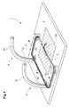
- FIG. 1 shows a strapping device 1 according to the invention schematically and in a highly simplified manner.
- This has, inter alia, a work surface 2, a groove 3 embedded in the work surface and two loop movement means 4.
- the groove 3 let into the work surface 2 runs essentially along the edges of a rectangle and serves as a guide means (guide channel) for guiding a strapping means, respectively. of the strapping band 5.
- the groove 3 is designed in such a way that the strapping band 5 can be introduced along by actively or passively pushing it in the direction of an arrow P from a supply store, for example a supply roll, which is located below the work surface 2.
- additional strap conveyors (not shown in detail), for example in the form of strap conveyor rollers (not shown in more detail), are provided, which support the introduction of the strapping 5 into the groove 3.
- the depth of the groove 3 is selected such that an inserted strapping band 5 does not protrude from the groove 3.
- Additional elastic elements such as lamellae or bristles, close the groove 3 towards the work surface 2 in such a way that the strapping 5 is secured against unwanted emergence and the risk of contamination of the groove 3 is reduced.
- the groove 3 can also be closed by means of a rigid element (not shown in detail) during the introduction of the strapping 5.
- a closing device 10 is used for tight closing of the strapping stretched around a stack (see FIG. 2) of printed products 5 to a ring.
- the locking device is, for example an ultrasonic welding device arranged in the area of the work surface 2 is. Of course, other devices for closing and sever the strapping 5 can be used.
- the two loop movement means 4 exist each from an arm 11 which protrudes from the work surface 2 in the region of the groove 3.
- the curved arms 11 are substantially parallel and extend in one Arch over the work surface 2 such that a stack to be strapped (see FIG 2) can be moved under or between them.
- a gripper 12 is slidably arranged in a guide groove 13 in a controlled manner. The grippers 12 protrude into the groove 3 in the waiting position shown and are designed such that they as soon as the strapping 5 forms a loop is inserted in the groove 3, temporarily capture and away from the work surface can erect.
- the arms 11 can be arranged movably or a changeable geometry have such that their position opposite the work surface 2, their lateral Distance and course changed, respectively. can be customized. This makes it possible Strapping stacks of different sizes at different stacking positions.
- the stack to be strapped can, respectively, between the arms or across them. be carried away. Due to the curvature and the course of the arms 11 can targeted influence on the loop while it is in the strapping position brought.
- the grippers 12 each consist of a plastic element (e.g. an elastic bracket) with a substantially u-shaped one Opening that serve to temporarily accommodate the strapping 5.
- This Plastic elements are each made by means of a steel string guided in the guide groove 13 (not shown in detail) driven.
- a drive device (not shown in detail) for rolling up and down the steel strings of each arm 11 is used.
- the arrangement shown is characterized inter alia by thereby from that the mass of the moving parts (gripper 12 and steel side, respectively. Loop from strapping) is very small and only a few parts move quickly Need to become.
- the grippers 12 serve as entrainment means for the strapping means 5.
- they can be used instead of the U-shaped opening shown here also have an opening with an o-shaped, slotted cross section, from which the strapping 5 can be pulled out laterally.
- Other configurations are possible.
- FIG. 2 shows, in a highly simplified and schematic manner, the device 1 according to the invention according to FIG. 1 with a stack 14 to be strapped on the work surface 2.
- This is shown in simplified form as a cuboid body.
- the strapping 5, which was previously formed into a loop in the waiting position in the work surface 2, is in a position which is erected by approximately 90 ° with respect to the work surface 2 (stacking position), to the side and above the stack 14 at a certain distance from it.
- the loop of strapping was erected by the grippers by moving them along the arms 11.
- the strapping 5 is contracted in the direction of arrows 15 by pulling it backwards into the storage reservoir (not shown in detail) arranged below the work surface 2.
- the strapping 5 is separated from the grippers 12.
- the grippers 12 are positioned depending on the stack position of the stack 14.
- the grippers 12 can be moved synchronously or asynchronously. This makes it e.g. possible while the stack 14 to be strapped is being fed At least partially straighten the loop.
- FIG. 3 shows the device according to FIGS. 1 and 2 with a strapped stack 14.
- the strapping band 5 is separated from the rest of the band and closed by means of the closing device 10 to form a ring.
- the grippers 12 are moved back to their starting position in the region of the work surface 2 in the direction of arrows 16. After the stack 14 is conveyed away, the device is ready for strapping another stack of printed products. While the new stack (not shown) is being fed, the loop is already being prepared in the loop guide means 3 for its strapping.
- the strapping of a stack has only been described in one direction for the sake of simplicity.
- the invention can also be designed so that more than one Strapping, e.g. is possible in two directions by adding more loop moving means 4 are provided.
- a turntable can be arranged, the additional orientation of the strapped Stack enables.
Landscapes
- Engineering & Computer Science (AREA)
- Mechanical Engineering (AREA)
- Basic Packing Technique (AREA)
- Finger-Pressure Massage (AREA)
- Thermotherapy And Cooling Therapy Devices (AREA)
- Microwave Tubes (AREA)
- Saccharide Compounds (AREA)
Abstract
Description
- Fig. 1
- eine bevorzugte Ausführungsform einer erfindungsgemässen Vorrichtung mit einer Schleife eines Umreifungsbands;
- Fig. 2
- die Vorrichtung gemäss Figur 1 mit einem zu umreifenden Stapel;
- Fig. 3
- die Vorrichtung gemäss Fig. 1 mit einem umreiften Stapel.
Claims (10)
- Umreifungsvorrichtung (1) zum Umreifen eines Körpers (14) mit einem Umreifungsmittel (5), dadurch gekennzeichnet, dass die Umreifungsvorrichtung (1) ein Führungsmittel (3) zum Führen des Umreifungsmittels (5) beinhaltet, welches Führungsmittel (3) zum Bilden einer Schleife aus Umreifungsmittel (5) in einer Warteposition, unabhängig von der Position des zu umreifenden Körpers (14), dient, und dass ein Schleifenbewegungsmittel (4) vorhanden ist, welches dazu dient um die durch das Führungsmittel (3) gebildete Schleife aus Umreifungsmittel (5) von der Warteposition in eine Stapelposition um einen zu umreifenden Körper (14) zu positionieren.
- Umreifungsvorrichtung (1) gemäss Patentanspruch 1, dadurch gekennzeichnet, dass das Führungsmittel (3) eine in eine Arbeitsfläche (2) eingelassene Nut (3) ist, in die das Umreifungsmittel (5) einschiebbar ist, und dass das Schleifenbewegungsmittel (4) mindestens einen aus der Arbeitsfläche (2) vorstehenden Arm (11) mit mindestens einem Greifer (12) aufweist, der entlang dem mindestens einen Arm (11) gesteuert verschiebbar angeordnet ist und als Mitnahmemittel zum Bewegen der Schleife aus Umreifungsmittel (5) von der Warteposition in die Stapelposition dient.
- Umreifungsvorrichtung (1) gemäss Patentanspruch 2, dadurch gekennzeichnet, dass der mindestens eine Arm (11) gekrümmt ist.
- Umreifungsvorrichtung (1) gemäss Patentanspruch 2 oder 3, dadurch gekennzeichnet, dass der mindestens eine Arm (11) gegenüber der Arbeitsfläche (2) beweglich angeordnet ist.
- Umreifungsvorrichtung (1) gemäss einem der Patentansprüche 2 bis 4, dadurch gekennzeichnet, dass der mindestens eine Greifer (12) eine Öffnung mit einem im Wesentlichen u-förmigen oder o-förmigen, seitlich geschlitzten Querschnitt aufweist, die zur temporären Aufnahme und Bewegung des Umreifungsmittels (5) dient und derart ausgestaltet ist, dass sie das Umreifungsmittel (5) in einer Stapelposition abgeben kann.
- Umreifungsvorrichtung (1) gemäss einem der Patentansprüche 2 bis 5, dadurch gekennzeichnet, dass im Innern des Arms (11) eine verschiebbare, angetriebene Saite angeordnet ist, die mit dem mindestens einen Greifer (12) verbunden ist und zu dessen Antrieb dient.
- Umreifungsvorrichtung (1) gemäss einem der Patentansprüche 2 bis 6, dadurch gekennzeichnet, dass Umreifungsvorrichtung (1) mindestens ein Elektromotor und/oder einen Luftdruckmotor und/oder einen Hydraulikmotor und/oder einen Magnetmotor und/oder einen piezoelektrischen Motor aufweist, der/die zum Antreiben des mindestens einen Greifers (12) dient/dienen.
- Umreifungsvorrichtung (1) gemäss einem der Patentansprüche 2 bis 7, dadurch gekennzeichnet, dass die Umreifungsvorrichtung (1) genau zwei Arme (11) mit je einem entlang diesen gesteuert verschiebbar angeordneten Greifer (12) aufweist.
- Umreifungsvorrichtung (1) gemäss einem der Patentansprüche 2 bis 8, dadurch gekennzeichnet, dass das Führungsmittel (3) im Wesentlichen entlang den Kanten eines Rechtecks verläuft.
- Umreifungsvorrichtung (1) gemäss einem der Patentansprüche 2 bis 9, dadurch gekennzeichnet, dass die Nut (3) mittels elastischen Elementen verschlossen ist.
Applications Claiming Priority (2)
| Application Number | Priority Date | Filing Date | Title |
|---|---|---|---|
| CH22592000 | 2000-11-20 | ||
| CH22592000 | 2000-11-20 |
Publications (2)
| Publication Number | Publication Date |
|---|---|
| EP1207107A1 true EP1207107A1 (de) | 2002-05-22 |
| EP1207107B1 EP1207107B1 (de) | 2004-08-18 |
Family
ID=4568263
Family Applications (1)
| Application Number | Title | Priority Date | Filing Date |
|---|---|---|---|
| EP01811064A Expired - Lifetime EP1207107B1 (de) | 2000-11-20 | 2001-11-01 | Umreifungsvorrichtung |
Country Status (5)
| Country | Link |
|---|---|
| US (2) | US20020083689A1 (de) |
| EP (1) | EP1207107B1 (de) |
| AT (1) | ATE273840T1 (de) |
| DE (1) | DE50103301D1 (de) |
| DK (1) | DK1207107T3 (de) |
Cited By (5)
| Publication number | Priority date | Publication date | Assignee | Title |
|---|---|---|---|---|
| WO2004002829A1 (de) | 2002-06-28 | 2004-01-08 | Ferag Ag | Umreifungsvorrichtung |
| EP1541472A1 (de) * | 2003-12-10 | 2005-06-15 | Ferag AG | Vorrichtung zum Umreifen von Gegenständen |
| US7150222B2 (en) | 2003-12-09 | 2006-12-19 | Signode Bernpak Gmbh | Apparatus longitudinally strapping a package, in particular a stack of newspapers, magazines or the like |
| DE102006038319A1 (de) * | 2006-08-15 | 2008-03-20 | Maschinenfabrik Gerd Mosca Ag | Längsumreifungsvorrichtung |
| CN104340400A (zh) * | 2014-10-31 | 2015-02-11 | 浙江依蕾毛纺织有限公司 | 纺织布简易打包机 |
Families Citing this family (6)
| Publication number | Priority date | Publication date | Assignee | Title |
|---|---|---|---|---|
| US7191788B2 (en) | 2004-03-05 | 2007-03-20 | The Coleman Company, Inc. | Tent with window having an internal shelf |
| EP1571086A1 (de) * | 2004-03-05 | 2005-09-07 | Kba-Giori S.A. | System zur Umhüllung von gestapelten Produkten und Verfahren |
| CA2579730C (en) * | 2004-09-13 | 2010-04-13 | Meadwestvaco Corporation | Banded envelopes and method for assembling a package of banded envelopes |
| US7789226B2 (en) * | 2004-09-13 | 2010-09-07 | Meadwestvaco Corporation | Packaged banded envelopes |
| DE102006038318A1 (de) * | 2006-08-15 | 2008-02-21 | Maschinenfabrik Gerd Mosca Ag | Bandumreifungsmaschine |
| CN114366229B (zh) * | 2022-02-14 | 2023-10-20 | 中国人民解放军陆军特色医学中心 | 一种高原新型爆炸武器伤早期救治用应急救援装置 |
Citations (6)
| Publication number | Priority date | Publication date | Assignee | Title |
|---|---|---|---|---|
| CH447007A (de) * | 1967-03-14 | 1967-11-15 | Mueller Hans Grapha Masch | Verfahren und Vorrichtung zum Bandieren von Papierbogenstapeln |
| US3977314A (en) * | 1973-05-24 | 1976-08-31 | Fuji Jidoki Kabushiki Kaisha | Tying device |
| DE4100267A1 (de) | 1990-01-08 | 1991-07-11 | Westinghouse Electric Corp | Digitaler torsionsmesser |
| DE4230730A1 (de) | 1992-09-14 | 1994-03-17 | Georg Lang | Umreifungsmaschine mit einem Bandführungsrahmen |
| EP0725005A1 (de) | 1995-02-01 | 1996-08-07 | SMB SCHWEDE MASCHINENBAU GmbH | Vorrichtung zum Umreifen von Packgut mit einem Umreifungsband |
| EP0905025A1 (de) * | 1997-09-27 | 1999-03-31 | SSB Strapping Systeme Bindlach GmbH | Umreifungsvorrichtung |
Family Cites Families (12)
| Publication number | Priority date | Publication date | Assignee | Title |
|---|---|---|---|---|
| US4062278A (en) * | 1976-12-20 | 1977-12-13 | Signode Corporation | Expanding strap loop forming and friction fusion machine |
| US4079667A (en) * | 1976-12-20 | 1978-03-21 | Signode Corporation | Method of forming and tensioning a strap loop about a package |
| USRE31353E (en) * | 1976-12-20 | 1983-08-23 | Signode Corporation | Expanding strap loop forming and friction fusion machine |
| US4378262A (en) * | 1981-02-04 | 1983-03-29 | Signode Corporation | Method and apparatus for forming and tensioning a strap loop about a package |
| US4534817A (en) * | 1983-04-08 | 1985-08-13 | Sullivan Denis P O | Automatic bundle-tying tool |
| JPS6367212A (ja) * | 1986-08-29 | 1988-03-26 | 株式会社 サト− | 自動梱包方法及び装置 |
| NL192100C (nl) * | 1987-05-27 | 1997-02-04 | Takami Masaho | Machine voor het met een band omsnoeren van een produkt. |
| US5078057A (en) * | 1990-01-05 | 1992-01-07 | Illinois Tool Works Inc. | Binding machine, such as strapping machine |
| US5121682A (en) * | 1990-06-01 | 1992-06-16 | Clements Industries, Inc. | Twist tie feed device |
| US5275674A (en) * | 1991-06-28 | 1994-01-04 | The Boeing Company | Method and apparatus for forming a welded identification sleeve |
| US5425826A (en) * | 1991-06-28 | 1995-06-20 | The Boeing Company | Method and apparatus for forming a welded identification sleeve |
| DE59202402D1 (de) * | 1991-11-30 | 1995-07-06 | Georg Lang | Vorrichtung zum Umreifen eines Packgutes mittels eines Bandes. |
-
2001
- 2001-11-01 EP EP01811064A patent/EP1207107B1/de not_active Expired - Lifetime
- 2001-11-01 AT AT01811064T patent/ATE273840T1/de not_active IP Right Cessation
- 2001-11-01 DE DE50103301T patent/DE50103301D1/de not_active Expired - Lifetime
- 2001-11-01 DK DK01811064T patent/DK1207107T3/da active
- 2001-11-16 US US09/992,189 patent/US20020083689A1/en not_active Abandoned
-
2003
- 2003-10-10 US US10/683,309 patent/US6901727B2/en not_active Expired - Fee Related
Patent Citations (6)
| Publication number | Priority date | Publication date | Assignee | Title |
|---|---|---|---|---|
| CH447007A (de) * | 1967-03-14 | 1967-11-15 | Mueller Hans Grapha Masch | Verfahren und Vorrichtung zum Bandieren von Papierbogenstapeln |
| US3977314A (en) * | 1973-05-24 | 1976-08-31 | Fuji Jidoki Kabushiki Kaisha | Tying device |
| DE4100267A1 (de) | 1990-01-08 | 1991-07-11 | Westinghouse Electric Corp | Digitaler torsionsmesser |
| DE4230730A1 (de) | 1992-09-14 | 1994-03-17 | Georg Lang | Umreifungsmaschine mit einem Bandführungsrahmen |
| EP0725005A1 (de) | 1995-02-01 | 1996-08-07 | SMB SCHWEDE MASCHINENBAU GmbH | Vorrichtung zum Umreifen von Packgut mit einem Umreifungsband |
| EP0905025A1 (de) * | 1997-09-27 | 1999-03-31 | SSB Strapping Systeme Bindlach GmbH | Umreifungsvorrichtung |
Cited By (8)
| Publication number | Priority date | Publication date | Assignee | Title |
|---|---|---|---|---|
| WO2004002829A1 (de) | 2002-06-28 | 2004-01-08 | Ferag Ag | Umreifungsvorrichtung |
| US7086213B2 (en) | 2002-06-28 | 2006-08-08 | Ferag Ag | Strapping device including loop forming channel and loop guide |
| AU2003223825B2 (en) * | 2002-06-28 | 2008-11-06 | Ferag Ag | Strapping device |
| US7150222B2 (en) | 2003-12-09 | 2006-12-19 | Signode Bernpak Gmbh | Apparatus longitudinally strapping a package, in particular a stack of newspapers, magazines or the like |
| EP1541472A1 (de) * | 2003-12-10 | 2005-06-15 | Ferag AG | Vorrichtung zum Umreifen von Gegenständen |
| DE102006038319A1 (de) * | 2006-08-15 | 2008-03-20 | Maschinenfabrik Gerd Mosca Ag | Längsumreifungsvorrichtung |
| DE102006038319B4 (de) * | 2006-08-15 | 2018-02-22 | Mosca Gmbh | Längsumreifungsvorrichtung und Verfahren zum Umreifen |
| CN104340400A (zh) * | 2014-10-31 | 2015-02-11 | 浙江依蕾毛纺织有限公司 | 纺织布简易打包机 |
Also Published As
| Publication number | Publication date |
|---|---|
| US20020083689A1 (en) | 2002-07-04 |
| DE50103301D1 (de) | 2004-09-23 |
| US6901727B2 (en) | 2005-06-07 |
| US20040163366A1 (en) | 2004-08-26 |
| EP1207107B1 (de) | 2004-08-18 |
| ATE273840T1 (de) | 2004-09-15 |
| DK1207107T3 (da) | 2004-12-06 |
Similar Documents
| Publication | Publication Date | Title |
|---|---|---|
| DE1782885C2 (de) | Vorrichtung zum Aufsetzen des Schieben und der oberen Endglieder auf verkonfektionierte gekuppelte Reißverschlüsse | |
| DE4310757B4 (de) | Objekt-Haltevorrichtung | |
| EP1955789B1 (de) | Biegemaschine | |
| EP1927412B1 (de) | Verfahren und Vorrichtung zum Vereinzeln stangenförmiger Körper | |
| EP1207107B1 (de) | Umreifungsvorrichtung | |
| DE2431244A1 (de) | Vorrichtung zum greifen, halten und transportieren von werkstuecken, insbesondere elektrischen spulen | |
| WO2007147566A1 (de) | Vorrichtung zur behandlung von flexiblen schlauchartigen gebilden mit wenigstens einer öffnung | |
| DE102009030012A1 (de) | Produktgreifer | |
| EP2607022B1 (de) | Eintreibvorrichtung | |
| DE3542496A1 (de) | Verfahren und vorrichtung zum zufuehren von montageteilen | |
| DE69003239T2 (de) | Orientierungs- und verpackungsvorrichtung für ampullen, insbesondere für ampullen für injektionsspritzen. | |
| EP2428452B1 (de) | Verfahren und Umreifungsvorrichtung zum Anlegen von Umreifungsbändern um Packstücke | |
| DE69601357T2 (de) | Automatische ziehvorrichtung | |
| EP1541470B1 (de) | Vorrichtung zum Längsumreifen eines Packstücks wie insbesondere eines Stapels von Zeitungen, Magazinen od.dgl. | |
| WO2019038359A1 (de) | Öffnungsstation und verfahren zum öffnen von schlauchfolie | |
| DE4421661B4 (de) | Vorrichtung zum Längsumreifen eines Gut-Stapels von Zeitschriften, Magazinen, Kartonagen o. dgl. | |
| EP0279393A2 (de) | Verstellbare Speicherkassette für Druckprodukte | |
| DE102014214019A1 (de) | Verfahren zur Herstellung von Umreifungsgebinden und Applikationseinheit einer Umreifungsvorrichtung zur Herstellung von Umreifungsgebinden | |
| CH671585A5 (de) | ||
| AT393641B (de) | Vorrichtung zum biegen von stahlstaeben zu betonbewehrungselementen | |
| DE10232580B4 (de) | Vorrichtung zum Umreifen, insbesondere zum Längsumreifen von Packgut mit einem Umreifungsband | |
| DE102007019187B3 (de) | Rebenbearbeitungseinrichtung | |
| AT392251B (de) | Vorrichtung zum ausrichten eines bleibend verformbaren verbindungsteiles | |
| DE202006009825U1 (de) | Vorrichtung zur Behandlung von flexiblen schlauchartigen Gebilden mit wenigstens einer Öffnung | |
| DE10229652B4 (de) | Schlitten für Rohrbiegemaschine |
Legal Events
| Date | Code | Title | Description |
|---|---|---|---|
| PUAI | Public reference made under article 153(3) epc to a published international application that has entered the european phase |
Free format text: ORIGINAL CODE: 0009012 |
|
| AX | Request for extension of the european patent |
Free format text: AL;LT;LV;MK;RO;SI |
|
| 17P | Request for examination filed |
Effective date: 20020712 |
|
| AKX | Designation fees paid |
Designated state(s): AT BE CH CY DE DK ES FI FR GB GR IE IT LI LU MC NL PT SE TR |
|
| 17Q | First examination report despatched |
Effective date: 20030818 |
|
| GRAP | Despatch of communication of intention to grant a patent |
Free format text: ORIGINAL CODE: EPIDOSNIGR1 |
|
| GRAS | Grant fee paid |
Free format text: ORIGINAL CODE: EPIDOSNIGR3 |
|
| GRAA | (expected) grant |
Free format text: ORIGINAL CODE: 0009210 |
|
| AK | Designated contracting states |
Kind code of ref document: B1 Designated state(s): AT BE CH CY DE DK ES FI FR GB GR IE IT LI LU MC NL PT SE TR |
|
| PG25 | Lapsed in a contracting state [announced via postgrant information from national office to epo] |
Ref country code: TR Free format text: LAPSE BECAUSE OF FAILURE TO SUBMIT A TRANSLATION OF THE DESCRIPTION OR TO PAY THE FEE WITHIN THE PRESCRIBED TIME-LIMIT Effective date: 20040818 Ref country code: IE Free format text: LAPSE BECAUSE OF FAILURE TO SUBMIT A TRANSLATION OF THE DESCRIPTION OR TO PAY THE FEE WITHIN THE PRESCRIBED TIME-LIMIT Effective date: 20040818 Ref country code: CY Free format text: LAPSE BECAUSE OF FAILURE TO SUBMIT A TRANSLATION OF THE DESCRIPTION OR TO PAY THE FEE WITHIN THE PRESCRIBED TIME-LIMIT Effective date: 20040818 Ref country code: FI Free format text: LAPSE BECAUSE OF FAILURE TO SUBMIT A TRANSLATION OF THE DESCRIPTION OR TO PAY THE FEE WITHIN THE PRESCRIBED TIME-LIMIT Effective date: 20040818 Ref country code: FR Free format text: LAPSE BECAUSE OF FAILURE TO SUBMIT A TRANSLATION OF THE DESCRIPTION OR TO PAY THE FEE WITHIN THE PRESCRIBED TIME-LIMIT Effective date: 20040818 |
|
| REG | Reference to a national code |
Ref country code: GB Ref legal event code: FG4D Free format text: NOT ENGLISH |
|
| REG | Reference to a national code |
Ref country code: CH Ref legal event code: EP |
|
| REG | Reference to a national code |
Ref country code: IE Ref legal event code: FG4D Free format text: GERMAN |
|
| REF | Corresponds to: |
Ref document number: 50103301 Country of ref document: DE Date of ref document: 20040923 Kind code of ref document: P |
|
| REG | Reference to a national code |
Ref country code: CH Ref legal event code: NV Representative=s name: FREI PATENTANWALTSBUERO |
|
| PG25 | Lapsed in a contracting state [announced via postgrant information from national office to epo] |
Ref country code: AT Free format text: LAPSE BECAUSE OF NON-PAYMENT OF DUE FEES Effective date: 20041101 Ref country code: LU Free format text: LAPSE BECAUSE OF NON-PAYMENT OF DUE FEES Effective date: 20041101 |
|
| GBT | Gb: translation of ep patent filed (gb section 77(6)(a)/1977) |
Effective date: 20041021 |
|
| PG25 | Lapsed in a contracting state [announced via postgrant information from national office to epo] |
Ref country code: GR Free format text: LAPSE BECAUSE OF FAILURE TO SUBMIT A TRANSLATION OF THE DESCRIPTION OR TO PAY THE FEE WITHIN THE PRESCRIBED TIME-LIMIT Effective date: 20041118 |
|
| REG | Reference to a national code |
Ref country code: SE Ref legal event code: TRGR |
|
| PG25 | Lapsed in a contracting state [announced via postgrant information from national office to epo] |
Ref country code: ES Free format text: LAPSE BECAUSE OF FAILURE TO SUBMIT A TRANSLATION OF THE DESCRIPTION OR TO PAY THE FEE WITHIN THE PRESCRIBED TIME-LIMIT Effective date: 20041129 |
|
| PG25 | Lapsed in a contracting state [announced via postgrant information from national office to epo] |
Ref country code: MC Free format text: LAPSE BECAUSE OF NON-PAYMENT OF DUE FEES Effective date: 20041130 Ref country code: BE Free format text: LAPSE BECAUSE OF NON-PAYMENT OF DUE FEES Effective date: 20041130 |
|
| REG | Reference to a national code |
Ref country code: DK Ref legal event code: T3 |
|
| REG | Reference to a national code |
Ref country code: IE Ref legal event code: FD4D |
|
| BERE | Be: lapsed |
Owner name: FERAG AG Effective date: 20041130 |
|
| PLBE | No opposition filed within time limit |
Free format text: ORIGINAL CODE: 0009261 |
|
| STAA | Information on the status of an ep patent application or granted ep patent |
Free format text: STATUS: NO OPPOSITION FILED WITHIN TIME LIMIT |
|
| 26N | No opposition filed |
Effective date: 20050519 |
|
| EN | Fr: translation not filed | ||
| BERE | Be: lapsed |
Owner name: *FERAG A.G. Effective date: 20041130 |
|
| PG25 | Lapsed in a contracting state [announced via postgrant information from national office to epo] |
Ref country code: PT Free format text: LAPSE BECAUSE OF NON-PAYMENT OF DUE FEES Effective date: 20050118 |
|
| PGFP | Annual fee paid to national office [announced via postgrant information from national office to epo] |
Ref country code: DK Payment date: 20101110 Year of fee payment: 10 Ref country code: NL Payment date: 20101111 Year of fee payment: 10 |
|
| PGFP | Annual fee paid to national office [announced via postgrant information from national office to epo] |
Ref country code: SE Payment date: 20101112 Year of fee payment: 10 Ref country code: IT Payment date: 20101123 Year of fee payment: 10 Ref country code: GB Payment date: 20101118 Year of fee payment: 10 |
|
| REG | Reference to a national code |
Ref country code: NL Ref legal event code: V1 Effective date: 20120601 |
|
| REG | Reference to a national code |
Ref country code: DK Ref legal event code: EBP |
|
| REG | Reference to a national code |
Ref country code: SE Ref legal event code: EUG |
|
| GBPC | Gb: european patent ceased through non-payment of renewal fee |
Effective date: 20111101 |
|
| PG25 | Lapsed in a contracting state [announced via postgrant information from national office to epo] |
Ref country code: NL Free format text: LAPSE BECAUSE OF NON-PAYMENT OF DUE FEES Effective date: 20120601 |
|
| PG25 | Lapsed in a contracting state [announced via postgrant information from national office to epo] |
Ref country code: IT Free format text: LAPSE BECAUSE OF NON-PAYMENT OF DUE FEES Effective date: 20111101 |
|
| PG25 | Lapsed in a contracting state [announced via postgrant information from national office to epo] |
Ref country code: DK Free format text: LAPSE BECAUSE OF NON-PAYMENT OF DUE FEES Effective date: 20111130 Ref country code: GB Free format text: LAPSE BECAUSE OF NON-PAYMENT OF DUE FEES Effective date: 20111101 Ref country code: SE Free format text: LAPSE BECAUSE OF NON-PAYMENT OF DUE FEES Effective date: 20111102 |
|
| PGFP | Annual fee paid to national office [announced via postgrant information from national office to epo] |
Ref country code: DE Payment date: 20121121 Year of fee payment: 12 Ref country code: CH Payment date: 20121031 Year of fee payment: 12 |
|
| REG | Reference to a national code |
Ref country code: CH Ref legal event code: PL |
|
| PG25 | Lapsed in a contracting state [announced via postgrant information from national office to epo] |
Ref country code: LI Free format text: LAPSE BECAUSE OF NON-PAYMENT OF DUE FEES Effective date: 20131130 Ref country code: CH Free format text: LAPSE BECAUSE OF NON-PAYMENT OF DUE FEES Effective date: 20131130 |
|
| REG | Reference to a national code |
Ref country code: DE Ref legal event code: R119 Ref document number: 50103301 Country of ref document: DE Effective date: 20140603 |
|
| PG25 | Lapsed in a contracting state [announced via postgrant information from national office to epo] |
Ref country code: DE Free format text: LAPSE BECAUSE OF NON-PAYMENT OF DUE FEES Effective date: 20140603 |