EP1207074B1 - Sitz- und/oder Liegevorrichtung, insbesondere Passagiersitz mit verstellbarer Rückenlehne - Google Patents
Sitz- und/oder Liegevorrichtung, insbesondere Passagiersitz mit verstellbarer Rückenlehne Download PDFInfo
- Publication number
- EP1207074B1 EP1207074B1 EP01124563A EP01124563A EP1207074B1 EP 1207074 B1 EP1207074 B1 EP 1207074B1 EP 01124563 A EP01124563 A EP 01124563A EP 01124563 A EP01124563 A EP 01124563A EP 1207074 B1 EP1207074 B1 EP 1207074B1
- Authority
- EP
- European Patent Office
- Prior art keywords
- seat
- cross
- frame
- members
- belt
- Prior art date
- Legal status (The legal status is an assumption and is not a legal conclusion. Google has not performed a legal analysis and makes no representation as to the accuracy of the status listed.)
- Expired - Lifetime
Links
Images

Classifications
-
- A—HUMAN NECESSITIES
- A47—FURNITURE; DOMESTIC ARTICLES OR APPLIANCES; COFFEE MILLS; SPICE MILLS; SUCTION CLEANERS IN GENERAL
- A47C—CHAIRS; SOFAS; BEDS
- A47C7/00—Parts, details, or accessories of chairs or stools
- A47C7/02—Seat parts
- A47C7/28—Seat parts with tensioned springs, e.g. of flat type
-
- B—PERFORMING OPERATIONS; TRANSPORTING
- B60—VEHICLES IN GENERAL
- B60N—SEATS SPECIALLY ADAPTED FOR VEHICLES; VEHICLE PASSENGER ACCOMMODATION NOT OTHERWISE PROVIDED FOR
- B60N2/00—Seats specially adapted for vehicles; Arrangement or mounting of seats in vehicles
- B60N2/24—Seats specially adapted for vehicles; Arrangement or mounting of seats in vehicles for particular purposes or particular vehicles
- B60N2/32—Seats specially adapted for vehicles; Arrangement or mounting of seats in vehicles for particular purposes or particular vehicles convertible for other use
- B60N2/34—Seats specially adapted for vehicles; Arrangement or mounting of seats in vehicles for particular purposes or particular vehicles convertible for other use into a bed
-
- B—PERFORMING OPERATIONS; TRANSPORTING
- B60—VEHICLES IN GENERAL
- B60N—SEATS SPECIALLY ADAPTED FOR VEHICLES; VEHICLE PASSENGER ACCOMMODATION NOT OTHERWISE PROVIDED FOR
- B60N2/00—Seats specially adapted for vehicles; Arrangement or mounting of seats in vehicles
- B60N2/58—Seat coverings
-
- B—PERFORMING OPERATIONS; TRANSPORTING
- B60—VEHICLES IN GENERAL
- B60N—SEATS SPECIALLY ADAPTED FOR VEHICLES; VEHICLE PASSENGER ACCOMMODATION NOT OTHERWISE PROVIDED FOR
- B60N2/00—Seats specially adapted for vehicles; Arrangement or mounting of seats in vehicles
- B60N2/70—Upholstery springs ; Upholstery
Definitions
- the invention relates to a passenger seat with adjustable backrest, comprising a seat frame of a seat part and an associated back frame of a backrest, wherein a seat surface is provided within the seat frame, the means for adjusting the surface stiffness of the seat from a hard rigidity to a softer stiffness.
- a seat device which is to allow for a seated an anatomically improved support and can adapt to the sitting postures of the body of the seated.
- a base part of transversely stiff, but lijnsflexiblem, corrugated spring plate is provided, the corrugation runs in the seat longitudinal direction.
- the transversely rigid and longitudinally flexible base part is suspended within a support frame and adjusts itself according to the individual wishes of the seat, ie in the case of different postures, the base part shifts according to the sitting posture.
- a possible adaptation to different postures is thus known from this solution by means of the resilient element as a base part, but can not be adapted to a sitting or a reclining suspension of the seat can be achieved.
- the suspension of the seat must be correspondingly harder than lying down. If you provide a longer lying in a passenger seat with reclining function with a tuned for seating harder seat suspension, it can thus be uncomfortable for a passenger while lying and cause back pain. If the seat is too softly cushioned, ergonomic seating requirements can not be realized, and especially during long periods of sitting (for example, on long-term flights), the passenger's well-being may be reduced.
- a chair which has elastic support elements.
- the support elements may be harder or softer. This is achieved with a wire which is pulled by a tensioning mechanism.
- the invention is therefore based on the object to achieve for a generic passenger seat a Weg lakefederung, each of which provides optimal comfort for sitting and lying on a passenger on this device and takes into account ergonomic considerations.
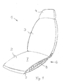
- Figures 1 and 2 show a perspective view of a sitting and / or reclining device 1, which has a seat part 2 and an adjustable backrest 3 substantially.
- a seat and / or reclining device 1 can be used in particular as a passenger seat in means of transport.
- a holding frame or attachment for the passenger seat 1 on a floor is not shown and is provided in accordance with customary, the prior art solutions.
- a headrest 4 and / or a foot part 5 can be provided on the passenger seat 1, in particular for the reclining position to allow the passenger a relaxed rest.
- the foot part 5 is arranged at the front edge of the seat part 2 and can be extended as required rolloartig.
- a material is to provide durable fabric, such as plastic fabric.
- On the seat part 2 a seat surface suspension 6 is provided, which is covered by a cushion element 7. Since the entire body weight of a passenger is distributed on a relatively small contact surface when sitting upright, the seat suspension must 6 of Seat 2 harder to be formed when lying. Providing the recliner function for longer seated occupancy of passenger seat 1 with a harder seat surface suspension tuned for sitting can make it uncomfortable for a passenger and cause back pain.
- the Wegdomfederung 6 is adjustable to the seat or reclining function, especially in long periods of sitting and / or lying (for example, long-haul flights) to realize ergonomic requirements with limited space and to increase the well-being of passengers.
- the seat suspension 6 is provided with arranged transversely to the seat longitudinal direction seat slats 8, which have a different hardness according to the function sitting or lying.
- the seat slats 8 consist of struts whose cross-sectional profile shape are designed so that an adjustment of the struts different stiffnesses can be achieved.
- the cross-sectional profiles may be formed, for example rectangular or oval-shaped. In Fig.
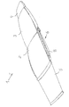
- a frame 9 is shown as a detail of the passenger seat 1.
- the frame 9 is formed from a seat frame 10 and a back frame 11.
- the back frame 10 is adjustable, so that - as shown in Fig. 4 it can be seen - the passenger seat 1 can also be placed in a lying position.
- the adjustment of the backrest 3 can be made electrically or mechanically, wherein adjustment mechanisms of known type can be used.
- An example, electrically driven drive element 12, such as a gear, can lower the back frame 11 via an operative connection with a arranged on the back frame 11 rack 13 (shown only schematically).
- the change in the hardness or stiffness of the seat suspension 6 is coupled to the lowering of the back frame 11.
- a shaft 15 is arranged, fixed to the back frame 11th connected is.
- the seat slats 8 - in the embodiment shown are seat slats 8A to 8K provided - are arranged transversely to the seat longitudinal direction S and mounted rotatably mounted on the seat frame 10.
- straps 16A to 16D an operative connection is made between the shaft 15 and the seat slats 8A to 8K.
- each strap 16A, 16B, 16C and 16D are provided, each extending from a fixation on the shaft 15 about the seat slats 8A to 8K wavy and each seat slat 8A to 8K at an attachment point 17A, 17B, 17C and 17D are fixed.
- the attachment points 17A, 17B, 17C and 17D to the seat slats are selected so that upon rotation of the shaft 15 about the rotation axis 14 when lowering the backrest 3, the straps 16A to 16D rotate the seat slats 8 from the upright position to the flat position.
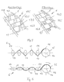
- the upright and the flat position of the seat slats 8A to 8K are shown in detail in FIGS. 5 and 6 in detail.
- the seat slats 8A to 8K are likewise turned back into their upright position.
- This can be realized either by spring means, for example coil springs (not shown) at the connection points of the individual seat slats 8A to 8K on the seat frame 10, wherein the seat slats 8A to 8K spring-loaded rotated in the flat position and dwell due to the tensile force of the belt in this position and go in the starting position back to their original position, or at least in the front edge of the seat frame 10 foremost seat slat 8A has such a spring device from the return to the belt tension in the direction of the backrest, the slat 8A bring by means of spring back into the upright position and on the Attachment points 17A to 17D from the belt 16A to 16D, the further fins 8B to 8K are also rotated in the vertical position.
- spring means for example coil springs (not shown) at the connection points of the individual seat slats 8A to 8K on the seat frame 10, wherein the seat s
- the straps 16A to 16D may be elastic at least in certain areas and cause due to their elasticity, a rotation of the seat slats 8A to 8K back to the starting position (upright) or at least support.
- FIGS. 5 and 6 details of the detail of the seat slats 8A to 8K can be seen, which are connected to one another by means of the straps 16A to 16D. Based on the side view in Fig. 6 is a possible Schlinganowski the straps 16A to 16D to the seat slats 8A to 8K and the attachment points 17A to 17D can be seen.
- adjustable seat suspension 6 is in the embodiment shown only one application. It is for example possible that in addition to the seat 6 and the backrest 3 is provided with adjustable blades within the back frame and adjustability of the hardness of the backrest can be done by means of the described inventive devices.
Landscapes
- Engineering & Computer Science (AREA)
- Aviation & Aerospace Engineering (AREA)
- Transportation (AREA)
- Mechanical Engineering (AREA)
- Seats For Vehicles (AREA)
- Chairs For Special Purposes, Such As Reclining Chairs (AREA)
- Chair Legs, Seat Parts, And Backrests (AREA)
Description
- Die Erfindung betrifft einen Passagiersitz mit verstellbarer Rückenlehne, bestehend aus einem Sitzrahmen eines Sitzteils und einem damit verbundenen Lehnenrahmen einer Rückenlehne, wobei eine Sitzflächenfederung innerhalb des Sitzrahmens vorgesehen ist, die Mittel zum Verstellen der Flächensteifigkeit der Sitzfläche von einer harten Steifigkeit in eine weichere Steifigkeit aufweist.
- Aus DE-PS 198 28 254 ist eine Sitzvorrichtung bekannt, die für einen Sitzenden eine anatomisch verbesserte Abstützung ermöglichen soll und sich den Sitzhaltungen des Körpers vom Sitzenden anpassen kann. Dafür ist ein Basisteil aus quersteifem, aber längsflexiblem, gewelltem Federblech vorgesehen, dessen Wellung in Sitzlängsrichtung verläuft. Das quersteife und längsflexible Basisteil ist innerhalb eines Trägerahmens eingehängt und stellt sich entsprechend der individuellen Sitzwünsche ein, d.h. bei unterschiedlichen Sitzhaltungen verlagert sich das Basisteil entsprechend der Sitzhaltung. Eine mögliche Anpassung an verschiedene Sitzhaltungen ist aus dieser Lösung somit mittels dem federnden Element als Basisteil bekannt, jedoch kann nicht eine an einen Sitz- oder einen Liegezustand angepasste Federung des Sitzes erreicht werden. Da beim aufrechten Sitzen das gesamte Körpergewicht auf eine relativ kleine Auflagefläche verteilt ist, muss die Federung der Sitzfläche entsprechend härter sein als beim Liegen. Wenn man in einem Passagiersitz mit Liegefunktion mit einer für das Sitzen abgestimmten härteren Sitzflächenfederung ein längeres Liegen vorsieht, kann es somit beim Liegen unkomfortabel für einen Passagier sein und zu Rückenschmerzen führen. Wenn die Sitzfläche zu weich gepolstert ist, lassen sich ergonomische Anforderungen an das Sitzen nicht realisieren und gerade bei langen Sitzphasen (beispielsweise bei Langzeitflügen) kann es zu einer Verminderung des Wohlbefindens des Passagiers kommen.
- Aus DE 299 01 156 U1 ist ein Sitzmöbel bekannt, welches elastische Stützelemente aufweist. Je nach Körpermasse können die Stützelemente härter oder weicher ausgebildet sein. Dies wird mit einem Draht erreicht, welcher durch einen Spannmechanismus gezogen wird.
- Der Erfindung liegt daher die Aufgabe zugrunde, für einen gattungsgemäßen Passagiersitz eine Sitzflächenfederung zu erreichen, der jeweils für das Sitzen und Liegen eines Passagiers auf dieser Vorrichtung einen optimalen Komfort bietet und ergonomische Gesichtspunkte berücksichtigt.
- Die Aufgabe wird bei einem gattungsgemäßen Passagiersitz durch die im Patentanspruch 1 bzw. 4 genannten Merkmalskombination gelöst.
- Dabei ist insbesondere von Vorteil, dass ohne einen großen Aufwand eine Verstellung der Sitzflächenfederung eines Passagiersitzes erreicht wird. Beim normalen Sitzen wird eine härtere Einstellung vorgenommen und für die Liegefunktion kann auf einfache Weise eine relativ weiche Federung der Sitzfläche erreicht werden, um auch ein komfortables Liegen zu ermöglichen.
- Weiterbildungen und vorteilhafte Ausgestaltungen sind in den Unteransprüchen 2 und 3 sowie 5 bis 9 angegeben sowie in der nachfolgenden Beschreibung erläutert.
- In der Zeichnung ist ein Ausführungsbeispiel der Erfindung dargestellt, das nachstehend anhand der Figuren 1 bis 6 näher beschrieben ist. In den Figuren sind gleiche Bauteile mit gleichen Bezugszeichen versehen.
- Es zeigen:
- Fig. 1
- eine Perspektivdarstellung eines erfindungsgemäßen Passagiersitzes in Sitzstellung,
- Fig. 2
- der Passagiersitz gemäß Fig. 1 in Liegeposition,
- Fig. 3
- eine Darstellung des Rahmengestells des Passagiersitzes mit einer erfindungsgemäßen Sitzflächenfederung,
- Fig. 4
- das Rahmengestell gemäß Fig. 3 in Liegeposition und
- Fign. 5 u. 6
- Detaildarstellung der Sitzflächenfederung in den Zuständen Sitzposition und Liegeposition.
- Die Figuren 1 und 2 zeigen in Perspektivdarstellung eine Sitz- und/oder Liegevorrichtung 1, die im wesentlichen ein Sitzteil 2 und eine verstellbare Rückenlehne 3 aufweist. Eine derartige Sitz- und/oder Liegevorrichtung 1 kann insbesondere als Passagiersitz in Verkehrsmitteln eingesetzt werden. Ein Haltegestell bzw. eine Befestigung für den Passagiersitz 1 auf einem Fußboden ist nicht dargestellt und ist gemäß üblichen, dem Stand der Technik entsprechenden Lösungen vorzusehen. Die Darstellung des Passagiersitzes 1 zeigt die Fig. 1 in normaler Sitzposition und die Fig. 2 in Liegeposition mit nach hinten abgesenkter Rückenlehne 3. Zur Komfortverbesserung kann am Passagiersitz 1 eine Kopfstütze 4 und/oder ein Fußteil 5 vorgesehen sein, um insbesondere für die Liegeposition dem Passagier ein entspanntes Ruhen zu ermöglichen. In Fig. 2 ist ersichtlich, dass das Fußteil 5 an der vorderen Kante des Sitzteiles 2 angeordnet ist und bei Bedarf rolloartig ausgefahren werden kann. Als Material ist strapazierfähiges Gewebe vorzusehen, beispielsweise Kunststoffgewebe. Am Sitzteil 2 ist eine Sitzflächenfederung 6 vorgesehen, die von einem Polsterelement 7 überzogen ist. Da beim aufrechten Sitzen das gesamte Körpergewicht eines Passagiers auf eine relativ kleine Auflagefläche verteilt ist, muss die Sitzflächenfederung 6 der Sitzfläche 2 härter als beim Liegen ausgebildet sein. Wenn man beim Passagiersitz 1 die Liegefunktion mit einer für das Sitzen abgestimmten härteren Sitzflächenfederung für ein längeres Liegen vorsieht, kann es unkomfortabel für einen Passagier sein und zu Rückenschmerzen führen. Erfindungsgemäß ist somit vorgesehen, dass die Sitzflächenfederung 6 auf die Sitz- oder Liegefunktion einstellbar ist, um gerade bei langen Sitz- und/oder Liegephasen (beispielsweise bei Langzeitflügen) mit beengten Platzverhältnissen ergonomische Anforderungen realisieren zu können und das Wohlbefinden der Passagiere zu steigern. Die Sitzflächenfederung 6 ist mit quer zur Sitzlängsrichtung angeordneten Sitzlamellen 8 versehen, die entsprechend der Funktion Sitzen oder Liegen eine unterschiedlich harte Federung aufweisen. Die Sitzlamellen 8 bestehen aus Streben, deren Querschnittsprofilform so ausgeführt sind, dass eine Verstellung der Streben jeweils unterschiedliche Steifigkeiten erreicht werden können. Die Querschnittsprofile können beispielsweise rechteckförmig oder ovalförmig ausgebildet sein. In Fig. 1 ist ersichtlich, dass eine relativ harte Federung der Sitzfläche mittels hochkant angeordneter Sitzlamellen 8 erreicht wird, demgegenüber in Fig. 2 durch Verdrehung der Lamellen 8 in eine flache Anordnung die Steifigkeit der Sitzlamellen 8 verringert wird und damit die Federung der Sitzfläche weicher wird.
- In den Figuren 3 und 4 ist als Einzelheit des Passagiersitzes 1 ein Rahmengestell 9 dargestellt. Das Rahmengestell 9 ist gebildet aus einem Sitzrahmen 10 und einem Lehnenrahmen 11. Der Lehnenrahmen 10 ist verstellbar, so dass - wie in Fig. 4 ersichtlich ist - der Passagiersitz 1 auch in Liegeposition gebracht werden kann. Die Verstellung der Rückenlehne 3 kann elektrisch oder mechanisch erfolgen, wobei Verstellmechanismen bekannter Art Anwendung finden können. Ein beispielsweise elektrisch angetriebenes Antriebselement 12, wie ein Zahnrad, kann über eine Wirkverbindung mit einer am Lehnenrahmen 11 angeordneten Zahnstange 13 (nur schematisch dargestellt) den Lehnenrahmen 11 absenken. Die Veränderung der Härte bzw. Steifigkeit der Sitzflächenfederung 6 ist an das Absenken des Lehnenrahmens 11 gekoppelt. In Drehachse 14 der Rückenlehne 3 ist eine Welle 15 angeordnet, die fest mit dem Lehnenrahmen 11 verbunden ist. Die Sitzlamellen 8 - in der gezeigten Ausführungsform sind Sitzlamellen 8A bis 8K vorgesehen - sind quer zur Sitzlängsrichtung S angeordnet und am Sitzrahmen 10 drehbar gelagert befestigt. Mittels Gurte 16A bis 16D wird zwischen der Welle 15 und den Sitzlamellen 8A bis 8K eine Wirkverbindung hergestellt. In der dargestellten Ausführungsform sind vier Gurte 16A, 16B, 16C und 16D vorgesehen, die jeweils ausgehend von einer Fixierung an der Welle 15 um die Sitzlamellen 8A bis 8K wellenförmig verlaufen und je Sitzlamelle 8A bis 8K an einem Befestigungspunkt 17A, 17B, 17C und 17D fixiert sind. Die Befestigungspunkte 17A, 17B, 17C und 17D an den Sitzlamellen sind so gewählt, dass bei einer Drehung der Welle 15 um die Drehachse 14 beim Absenken der Rückenlehne 3 die Gurte 16A bis 16D die Sitzlamellen 8 von der Hochkantlage in die Flachlage verdrehen. Die Hochkant- und die Flachlage der Sitzlamellen 8A bis 8K sind als Einzelheitdarstellungen in den Figuren 5 und 6 detailliert gezeigt.
Bei einem Hochklappen der Rückenlehne 3 ist vorgesehen, dass die Sitzlamellen 8A bis 8K ebenfalls wieder in ihre Hochkantlage zurückgedreht werden. Das kann entweder durch Federeinrichtungen, beispielsweise Spiralfedern (nicht gezeigt) an den Anschlusspunkten der einzelnen Sitzlamellen 8A bis 8K am Sitzrahmen 10 realisiert werden, wobei die Sitzlamellen 8A bis 8K federbelastet in die Flachlage gedreht werden und aufgrund der Zugkraft vom Gurt in dieser Lage verweilen und bei Wegfall der Gurtzugkraft wieder zurück in ihre Ausgangslage gehen, oder mindestens die im Bereich der Vorderkante des Sitzrahmens 10 vorderste Sitzlamelle 8A weist eine derartige Federeinrichtung aus die bei Wegfall der Gurtzugkraft in Richtung Rückenlehne die Lamelle 8A mittels Federkraft wieder in die Hochkantposition bringen und über die Befestigungspunkte 17A bis 17D vom Gurt 16A bis 16D die weiteren Lamellen 8B bis 8K ebenfalls in die Hochkantlage gedreht werden.
In einer weiteren, nicht bildlich dargestelltem Ausführungsform können auch die Gurte 16A bis 16D zumindest in bestimmten Bereichen elastisch ausgeführt sein und aufgrund ihrer Elastizität ein Drehen der Sitzlamellen 8A bis 8K zurück in die Ausgangslage (hochkant) bewirken oder zumindest unterstützen. - In den Figuren 5 und 6 sind in Detaildarstellungen ausschnittsweise die Sitzlamellen 8A bis 8K ersichtlich, die mittels der Gurte 16A bis 16D miteinander verbunden sind. Anhand der Seitenansicht in Fig. 6 ist eine mögliche Schlinganordnung der Gurte 16A bis 16D um die Sitzlamellen 8A bis 8K sowie die Befestigungspunkte 17A bis 17D ersichtlich.
- Die erfindungsgemäß verstellbare Sitzflächenfederung 6 ist in der gezeigten Ausführung nur ein Anwendungsfall. Es ist beispielsweise möglich, dass neben der Sitzfläche 6 auch die Rückenlehne 3 mit verstellbaren Lamellen innerhalb des Lehnenrahmens vorgesehen ist und eine Einstellbarkeit der Härte der Lehne mittels der beschriebenen erfindungsgemäßen Einrichtungen erfolgen kann.
-
1 - Passagiersitz 2 - Sitzteil 3 - Rückenlehne 4 - Kopfstütze 5 - Fußteil 6 - Sitzflächenfederung 7 - Sitzpolster (Polsterelement) 8 - Sitzlamellen (8A - 8K) 9 - Rahmengestell 10 - Sitzrahmen 11 - Lehnenrahmen 12 - Antriebselement (Zahnrad) 13 - Zahnstange 14 - Drehachse der Rückenlehne 15 - Welle 16 - Gurt (16A - 16D) 17 - Befestigungspunkt (17A - 17D)
Claims (9)
- Passagiersitz mit verstellbarer Rückenlehne (3), bestehend aus einem Sitzrahmen (10) eines Sitzteils (2) und einem damit verbundenen Lehnenrahmen (11) der Rückenlehne (3), wobei eine Sitzflächenfederung (6) innerhalb des Sitzrahmens (10) vorgesehen ist, die Mittel zum Verstellen (8, 15, 16, 17) der Flächensteifigkeit der Sitzfläche von einer harten Steifigkeit für die Sitzposition in eine weichere Steifigkeit für die Liegeposition aufweist, dadurch gekennzeichnet, dass die Sitzflächenfederung (6) aus Sitzlamellen (8, 8A - 8K) gebildet ist, die quer zur Sitzlängsrichtung innerhalb des Sitzrahmens (10) angeordnet und drehbar gelagert sind, wobei mittels einer Drehung der Sitzlamellen (8, 8A - 8K) eine Veränderung der Sitzhärte erreichbar ist und die Drehung der Sitzlamellen (8, 8A - 8K) an die Verstellung der Rückenlehne (3) gekoppelt ist.
- Passagiersitz nach Anspruch 1,
dadurch gekennzeichnet, dass
der Querschnitt einer Sitzlamelle (8, 8A - 8K) so ausgebildet ist, dass in Querschnittslängsrichtung eine größere Steifigkeit als in Querschnittsquerrichtung erreicht ist. - Passagiersitz nach einem der Ansprüche 1 oder 2,
dadurch gekennzeichnet, dass
der Querschnitt der Sitzlamellen (8, 8A - 8K) ovalförmig, stegförmig oder rechteckförmig ausgebildet ist. - Passagiersitz mit verstellbarer Rückenlehne (3), bestehend aus einem Sitzrahmen (10) eines Sitzteils (2) und einem damit verbundenen Lehnenrahmen (11) der Rückenlehne (3), wobei eine Sitzflächenfederung (6) innerhalb des Sitzrahmens (10) vorgesehen ist, die Mittel zum Verstellen (8, 15, 16, 17) der Flächensteifigkeit der Sitzfläche von einer harten Steifigkeit für die Sitzposition in eine weichere Steifigkeit für die Liegeposition aufweist, dadurch gekennzeichnet, dass der Lehnenrahmen (11) im Bereich einer Drehachse (14) der Verstellbewegung zumindest einen Befestigungspunkt zumindest eines ersten Endes eines Gurtes (16A - 16D) aufweist und der zumindest eine Gurt (16A - 16D) an Befestigungspunkten (17A - 17D) mit Sitzlamellen (8, 8A - 8K) verbunden ist, wobei der zumindest eine Gurt (16A - 16D) wellenförmig um die Sitzlamellen (8, 8B bis 8K) geführt und an der im Bereich der Vorderkante des Sitzrahmens (10) vordersten Sitzlamelle (8A) mit dem zweiten Ende befestigt ist.
- Passagiersitz nach Anspruch 4,
dadurch gekennzeichnet, dass
am Lehnenrahmen (11) eine Welle (15) fest angeordnet ist, wobei die Wellenachse identisch mit der Drehachse (14) vom Lehnenrahmen (11) ist, der Befestigungspunkt des ersten Gurtendes (16A - 16D) auf dem Umfang der Welle (15) vorgesehen ist und bei Drehung des Lehnenrahmens (11) in Liegeposition am Umfang der Welle (15) eine Umwicklung des zumindest einen Gurtes (16A - 16D) erfolgt und die Sitzlamellen (8A - 8K) durch Verschiebung des Gurtes (16A -16D) in Rückenlehnenrichtung in eine Flachlage drehbar sind. - Passagiersitz nach einem der Ansprüche 4 oder 5,
dadurch gekennzeichnet, dass
bei Drehung des Lehnenrahmens (11) in die Ausgangslage die Sitzlamellen (8, 8A - 8K) in die Hochkantlage drehbar sind. - Passagiersitz nach Anspruch 6,
dadurch gekennzeichnet, dass
mindestens die im Bereich der Vorderkante des Sitzrahmens (10) erste Sitzlamelle (8A) oder mehrere Sitzlamellen (8A - 8K) mit einer Federeinrichtung zum Erreichen der Ausgangslage versehen sind. - Passagiersitz nach einem der Ansprüche 4 bis 7,
dadurch gekennzeichnet, dass
der zumindest eine Gurt (16A - 16D) mindestens bereichsweise elastisch ausgeführt ist. - Passagiersitz nach einem der vorangegangenen Ansprüche,
dadurch gekennzeichnet, dass
ein Fußteil (5) mit einer rolloartig herausfahrbaren Abstützfläche im Bereich der Vorderkante des Sitzrahmens (10) angeordnet ist.
Applications Claiming Priority (2)
| Application Number | Priority Date | Filing Date | Title |
|---|---|---|---|
| DE10057208 | 2000-11-17 | ||
| DE10057208A DE10057208A1 (de) | 2000-11-17 | 2000-11-17 | Sitz- und/oder Liegevorrichtung, insbesondere Passagiersitz mit verstellbarer Rückenlehne |
Publications (2)
| Publication Number | Publication Date |
|---|---|
| EP1207074A1 EP1207074A1 (de) | 2002-05-22 |
| EP1207074B1 true EP1207074B1 (de) | 2006-06-07 |
Family
ID=7663763
Family Applications (1)
| Application Number | Title | Priority Date | Filing Date |
|---|---|---|---|
| EP01124563A Expired - Lifetime EP1207074B1 (de) | 2000-11-17 | 2001-10-15 | Sitz- und/oder Liegevorrichtung, insbesondere Passagiersitz mit verstellbarer Rückenlehne |
Country Status (5)
| Country | Link |
|---|---|
| US (1) | US6609753B2 (de) |
| EP (1) | EP1207074B1 (de) |
| AT (1) | ATE328757T1 (de) |
| DE (2) | DE10057208A1 (de) |
| ES (1) | ES2264675T3 (de) |
Cited By (2)
| Publication number | Priority date | Publication date | Assignee | Title |
|---|---|---|---|---|
| DE102010055994A1 (de) | 2010-12-23 | 2012-06-28 | Airbus Operations Gmbh | Liege- oder Sitzvorrichtung |
| WO2024100098A1 (de) * | 2022-11-08 | 2024-05-16 | Zim Aircraft Seating Gmbh | Fluggastsitz |
Families Citing this family (18)
| Publication number | Priority date | Publication date | Assignee | Title |
|---|---|---|---|---|
| US7108226B2 (en) * | 2003-10-10 | 2006-09-19 | The Boeing Company | Interior seating architecture for aircraft |
| DE102005041840B3 (de) * | 2005-09-02 | 2007-04-26 | Airbus Deutschland Gmbh | Passagiersitz mit individueller Anpassung an einen Passagier |
| CA2541583A1 (en) * | 2006-03-31 | 2007-09-30 | 155124 Canada Inc. | Seat structure with elastic suspension |
| US7866723B2 (en) * | 2006-10-13 | 2011-01-11 | Ninio V Guy | Vehicular seat for handicapped and elderly passengers |
| EP2878231B2 (de) * | 2007-10-03 | 2019-06-19 | Volvo Lastvagnar AB | Fahrzeug-Bett-Couch |
| SE532788C2 (sv) | 2007-10-23 | 2010-04-13 | Stjernfjaedrar Ab | Bädd med variabel storlek samt ett fordon innefattande en sådan bädd |
| DE102008028791A1 (de) * | 2008-06-17 | 2009-12-24 | Bayerische Motoren Werke Aktiengesellschaft | Sitz für ein Kraftfahrzeug mit stufenloser Sitzhärtenverstellung |
| FR2935684B1 (fr) | 2008-09-10 | 2011-05-13 | Airbus | Systeme de sieges pour passager integrant un meuble multi-fonctionnel, et aeronef comprenant un tel systeme |
| ITTO20110355A1 (it) * | 2011-04-21 | 2012-10-22 | Red S R L | Struttura di appoggio, in particolare per un veicolo |
| IN2014DN08535A (de) | 2012-05-07 | 2015-05-15 | Johnson Controls Tech Co | |
| DE102012013208B4 (de) | 2012-05-07 | 2019-07-25 | Adient Luxembourg Holding S.À R.L. | Sitzteil eines Fahrzeugsitzes |
| DE102012208721A1 (de) * | 2012-05-24 | 2013-11-28 | Lufthansa Technik Ag | Flugzeugsitz mit einer Sitzbaugruppe |
| US8998323B2 (en) | 2012-08-09 | 2015-04-07 | Ami Industries, Inc. | Warped-floor tolerant aircraft seat |
| DE102014101441A1 (de) | 2014-02-05 | 2015-08-06 | Airbus Operations Gmbh | Passagiersitz für ein Luftfahrzeug |
| US9623777B2 (en) | 2015-06-18 | 2017-04-18 | Nissan North America, Inc. | Vehicle seat assembly |
| EP3562350B1 (de) * | 2016-12-06 | 2023-02-08 | Arjuna Indraeswaran Rajasingham | Sitz für einen insassen |
| EP3977904B1 (de) | 2019-03-11 | 2022-10-12 | Storyteller Overland, LLC | Rv-nachrüstsystem |
| NL2029202B1 (nl) * | 2021-09-17 | 2023-03-24 | P R Sella B V | Een zitting |
Family Cites Families (10)
| Publication number | Priority date | Publication date | Assignee | Title |
|---|---|---|---|---|
| US280004A (en) * | 1883-06-26 | Camp-chair and cot | ||
| DE3328801A1 (de) * | 1983-08-10 | 1985-03-07 | Paulisch Kg, 8770 Lohr | Federung fuer sitze, insbesondere von kraftfahrzeugen |
| US5194311A (en) | 1985-04-09 | 1993-03-16 | Deutsche Airbus Gmbh | Cushioning core and seat construction especially for an aircraft seat |
| US4858992A (en) * | 1985-10-07 | 1989-08-22 | Lasota Larry | Conformable seat |
| DE3702262A1 (de) * | 1987-01-27 | 1988-08-04 | Basf Ag | Sitz fuer kraftfahrzeuge |
| US4921301A (en) * | 1988-01-25 | 1990-05-01 | Haynes R Jalaine | Maternity lounger |
| EP0639479B1 (de) * | 1993-08-20 | 1997-10-15 | Britax Rumbold Limited | Fahrgastsitz |
| DE19534024C2 (de) | 1995-09-14 | 1997-07-10 | Daimler Benz Aerospace Airbus | Sitzgruppe, insbesondere in einer Passagierkabine eines Flugzeuges |
| DE19828254C2 (de) | 1998-06-25 | 2000-07-20 | Daimler Chrysler Ag | Sitz- und/oder Liegevorrichtung, insbesondere Fahr- oder Flugzeugsitz |
| DE29901156U1 (de) * | 1999-01-25 | 1999-05-12 | Heidinger, Florian, Dr., 83627 Warngau | Sitzmöbel, insbesondere Bürostuhl |
-
2000
- 2000-11-17 DE DE10057208A patent/DE10057208A1/de not_active Withdrawn
-
2001
- 2001-10-15 EP EP01124563A patent/EP1207074B1/de not_active Expired - Lifetime
- 2001-10-15 AT AT01124563T patent/ATE328757T1/de not_active IP Right Cessation
- 2001-10-15 DE DE50110022T patent/DE50110022D1/de not_active Expired - Lifetime
- 2001-10-15 ES ES01124563T patent/ES2264675T3/es not_active Expired - Lifetime
- 2001-11-15 US US09/991,014 patent/US6609753B2/en not_active Expired - Fee Related
Cited By (2)
| Publication number | Priority date | Publication date | Assignee | Title |
|---|---|---|---|---|
| DE102010055994A1 (de) | 2010-12-23 | 2012-06-28 | Airbus Operations Gmbh | Liege- oder Sitzvorrichtung |
| WO2024100098A1 (de) * | 2022-11-08 | 2024-05-16 | Zim Aircraft Seating Gmbh | Fluggastsitz |
Also Published As
| Publication number | Publication date |
|---|---|
| DE50110022D1 (de) | 2006-07-20 |
| DE10057208A1 (de) | 2002-05-29 |
| US6609753B2 (en) | 2003-08-26 |
| ATE328757T1 (de) | 2006-06-15 |
| EP1207074A1 (de) | 2002-05-22 |
| ES2264675T3 (es) | 2007-01-16 |
| US20020060484A1 (en) | 2002-05-23 |
Similar Documents
| Publication | Publication Date | Title |
|---|---|---|
| EP1207074B1 (de) | Sitz- und/oder Liegevorrichtung, insbesondere Passagiersitz mit verstellbarer Rückenlehne | |
| DE19828254C2 (de) | Sitz- und/oder Liegevorrichtung, insbesondere Fahr- oder Flugzeugsitz | |
| EP0317726B1 (de) | Sitz für ein Fahrzeug, Flugzeug oder dergleichen | |
| EP1239753B1 (de) | Verstellbare polsterungseinrichtung für ein sitz- und/oder liegemöbel | |
| DE68902020T2 (de) | Kraftfahrzeugsitz. | |
| EP1056371B1 (de) | Liegebett | |
| DE1554084C3 (de) | Sitz, insbesondere Kraftfahrzeugsitz | |
| DE69005766T2 (de) | Eine Rückenlehne für einen Sitz, insbesondere einen Kraftfahrzeugsitz. | |
| EP1293152A2 (de) | Polster für Sitze, insbesondere Fahrzeugsitze | |
| EP3568317B1 (de) | Lordosenstütze für einen sitz | |
| CH700928B1 (de) | Personensitz mit einer Wippfeder. | |
| EP0253222B1 (de) | Fahrzeugsitz mit einem durch Höhenverstellung der Sitzvorderkante neigungsverstellbaren Sitzkissen | |
| DE10301326A1 (de) | Sitzmöbel, insbesondere Sessel | |
| DE10027686A1 (de) | Sitzbank und/oder Einzelsitz, insbesondere für ein Fahrzeug | |
| DE4106862A1 (de) | Kraftfahrzeugsitz | |
| DE2344534A1 (de) | Transportable rueckenstuetze | |
| EP0181591B1 (de) | Auflage für eine liegende oder sitzende Person | |
| DE19826436A1 (de) | Polstermöbel mit verstellbarer Sitzhöhe und/oder Sitzhärte | |
| DE19811229C2 (de) | Kopfstützen in KFZ | |
| DE19510789A1 (de) | Fahrzeugsitz mit auswechselbaren seitlichen Stützpolstern am Sitzkissen und an der Rückenlehne | |
| EP1959795B1 (de) | Rückenlehne und stuhl | |
| DE10126204B4 (de) | Verstellbare Stützeinrichtung für eine Polsterung eines Sitz-und /oder Liegemöbels | |
| DE3037659C2 (de) | Rückenstütze | |
| EP2689692A1 (de) | Sitzmöbel, insbesondere Bürostuhl | |
| EP1699319B1 (de) | Sitz- oder liegemöbel |
Legal Events
| Date | Code | Title | Description |
|---|---|---|---|
| PUAI | Public reference made under article 153(3) epc to a published international application that has entered the european phase |
Free format text: ORIGINAL CODE: 0009012 |
|
| AX | Request for extension of the european patent |
Free format text: AL;LT;LV;MK;RO;SI |
|
| 17P | Request for examination filed |
Effective date: 20021122 |
|
| AKX | Designation fees paid |
Designated state(s): AT BE CH CY DE DK ES FI FR GB GR IE IT LI LU MC NL PT SE TR |
|
| 17Q | First examination report despatched |
Effective date: 20050225 |
|
| GRAP | Despatch of communication of intention to grant a patent |
Free format text: ORIGINAL CODE: EPIDOSNIGR1 |
|
| GRAS | Grant fee paid |
Free format text: ORIGINAL CODE: EPIDOSNIGR3 |
|
| GRAA | (expected) grant |
Free format text: ORIGINAL CODE: 0009210 |
|
| AK | Designated contracting states |
Kind code of ref document: B1 Designated state(s): AT BE CH CY DE DK ES FI FR GB GR IE IT LI LU MC NL PT SE TR |
|
| PG25 | Lapsed in a contracting state [announced via postgrant information from national office to epo] |
Ref country code: IT Free format text: LAPSE BECAUSE OF FAILURE TO SUBMIT A TRANSLATION OF THE DESCRIPTION OR TO PAY THE FEE WITHIN THE PRESCRIBED TIME-LIMIT;WARNING: LAPSES OF ITALIAN PATENTS WITH EFFECTIVE DATE BEFORE 2007 MAY HAVE OCCURRED AT ANY TIME BEFORE 2007. THE CORRECT EFFECTIVE DATE MAY BE DIFFERENT FROM THE ONE RECORDED. Effective date: 20060607 Ref country code: IE Free format text: LAPSE BECAUSE OF FAILURE TO SUBMIT A TRANSLATION OF THE DESCRIPTION OR TO PAY THE FEE WITHIN THE PRESCRIBED TIME-LIMIT Effective date: 20060607 Ref country code: NL Free format text: LAPSE BECAUSE OF FAILURE TO SUBMIT A TRANSLATION OF THE DESCRIPTION OR TO PAY THE FEE WITHIN THE PRESCRIBED TIME-LIMIT Effective date: 20060607 Ref country code: FI Free format text: LAPSE BECAUSE OF FAILURE TO SUBMIT A TRANSLATION OF THE DESCRIPTION OR TO PAY THE FEE WITHIN THE PRESCRIBED TIME-LIMIT Effective date: 20060607 |
|
| REG | Reference to a national code |
Ref country code: GB Ref legal event code: FG4D Free format text: NOT ENGLISH |
|
| REG | Reference to a national code |
Ref country code: CH Ref legal event code: EP |
|
| REG | Reference to a national code |
Ref country code: IE Ref legal event code: FG4D Free format text: LANGUAGE OF EP DOCUMENT: GERMAN |
|
| REF | Corresponds to: |
Ref document number: 50110022 Country of ref document: DE Date of ref document: 20060720 Kind code of ref document: P |
|
| GBT | Gb: translation of ep patent filed (gb section 77(6)(a)/1977) |
Effective date: 20060816 |
|
| PG25 | Lapsed in a contracting state [announced via postgrant information from national office to epo] |
Ref country code: DK Free format text: LAPSE BECAUSE OF FAILURE TO SUBMIT A TRANSLATION OF THE DESCRIPTION OR TO PAY THE FEE WITHIN THE PRESCRIBED TIME-LIMIT Effective date: 20060907 |
|
| REG | Reference to a national code |
Ref country code: SE Ref legal event code: TRGR |
|
| PG25 | Lapsed in a contracting state [announced via postgrant information from national office to epo] |
Ref country code: CH Free format text: LAPSE BECAUSE OF NON-PAYMENT OF DUE FEES Effective date: 20061031 Ref country code: LI Free format text: LAPSE BECAUSE OF NON-PAYMENT OF DUE FEES Effective date: 20061031 Ref country code: MC Free format text: LAPSE BECAUSE OF NON-PAYMENT OF DUE FEES Effective date: 20061031 |
|
| PG25 | Lapsed in a contracting state [announced via postgrant information from national office to epo] |
Ref country code: PT Free format text: LAPSE BECAUSE OF FAILURE TO SUBMIT A TRANSLATION OF THE DESCRIPTION OR TO PAY THE FEE WITHIN THE PRESCRIBED TIME-LIMIT Effective date: 20061107 |
|
| NLV1 | Nl: lapsed or annulled due to failure to fulfill the requirements of art. 29p and 29m of the patents act | ||
| ET | Fr: translation filed | ||
| REG | Reference to a national code |
Ref country code: ES Ref legal event code: FG2A Ref document number: 2264675 Country of ref document: ES Kind code of ref document: T3 |
|
| REG | Reference to a national code |
Ref country code: IE Ref legal event code: FD4D |
|
| PLBE | No opposition filed within time limit |
Free format text: ORIGINAL CODE: 0009261 |
|
| STAA | Information on the status of an ep patent application or granted ep patent |
Free format text: STATUS: NO OPPOSITION FILED WITHIN TIME LIMIT |
|
| 26N | No opposition filed |
Effective date: 20070308 |
|
| REG | Reference to a national code |
Ref country code: CH Ref legal event code: PL |
|
| BERE | Be: lapsed |
Owner name: AIRBUS DEUTSCHLAND G.M.B.H. Effective date: 20061031 |
|
| PG25 | Lapsed in a contracting state [announced via postgrant information from national office to epo] |
Ref country code: AT Free format text: LAPSE BECAUSE OF NON-PAYMENT OF DUE FEES Effective date: 20061015 |
|
| PG25 | Lapsed in a contracting state [announced via postgrant information from national office to epo] |
Ref country code: GR Free format text: LAPSE BECAUSE OF FAILURE TO SUBMIT A TRANSLATION OF THE DESCRIPTION OR TO PAY THE FEE WITHIN THE PRESCRIBED TIME-LIMIT Effective date: 20060908 |
|
| PG25 | Lapsed in a contracting state [announced via postgrant information from national office to epo] |
Ref country code: LU Free format text: LAPSE BECAUSE OF NON-PAYMENT OF DUE FEES Effective date: 20061015 Ref country code: TR Free format text: LAPSE BECAUSE OF FAILURE TO SUBMIT A TRANSLATION OF THE DESCRIPTION OR TO PAY THE FEE WITHIN THE PRESCRIBED TIME-LIMIT Effective date: 20060607 |
|
| PG25 | Lapsed in a contracting state [announced via postgrant information from national office to epo] |
Ref country code: CY Free format text: LAPSE BECAUSE OF FAILURE TO SUBMIT A TRANSLATION OF THE DESCRIPTION OR TO PAY THE FEE WITHIN THE PRESCRIBED TIME-LIMIT Effective date: 20060607 |
|
| PG25 | Lapsed in a contracting state [announced via postgrant information from national office to epo] |
Ref country code: BE Free format text: LAPSE BECAUSE OF FAILURE TO SUBMIT A TRANSLATION OF THE DESCRIPTION OR TO PAY THE FEE WITHIN THE PRESCRIBED TIME-LIMIT Effective date: 20061031 |
|
| PGFP | Annual fee paid to national office [announced via postgrant information from national office to epo] |
Ref country code: SE Payment date: 20101014 Year of fee payment: 10 Ref country code: IT Payment date: 20101025 Year of fee payment: 10 |
|
| PGFP | Annual fee paid to national office [announced via postgrant information from national office to epo] |
Ref country code: ES Payment date: 20101025 Year of fee payment: 10 |
|
| REG | Reference to a national code |
Ref country code: ES Ref legal event code: PC2A Owner name: AIRBUS OPERATIONS GMBH Effective date: 20110930 |
|
| REG | Reference to a national code |
Ref country code: FR Ref legal event code: CD Owner name: AIRBUS OPERATIONS GMBH Effective date: 20111118 |
|
| REG | Reference to a national code |
Ref country code: SE Ref legal event code: EUG |
|
| PG25 | Lapsed in a contracting state [announced via postgrant information from national office to epo] |
Ref country code: IT Free format text: LAPSE BECAUSE OF NON-PAYMENT OF DUE FEES Effective date: 20111015 |
|
| PG25 | Lapsed in a contracting state [announced via postgrant information from national office to epo] |
Ref country code: SE Free format text: LAPSE BECAUSE OF NON-PAYMENT OF DUE FEES Effective date: 20111016 |
|
| REG | Reference to a national code |
Ref country code: ES Ref legal event code: FD2A Effective date: 20130606 |
|
| PG25 | Lapsed in a contracting state [announced via postgrant information from national office to epo] |
Ref country code: ES Free format text: LAPSE BECAUSE OF NON-PAYMENT OF DUE FEES Effective date: 20111016 |
|
| REG | Reference to a national code |
Ref country code: FR Ref legal event code: PLFP Year of fee payment: 15 |
|
| REG | Reference to a national code |
Ref country code: FR Ref legal event code: PLFP Year of fee payment: 16 |
|
| PGFP | Annual fee paid to national office [announced via postgrant information from national office to epo] |
Ref country code: FR Payment date: 20161020 Year of fee payment: 16 Ref country code: DE Payment date: 20161020 Year of fee payment: 16 Ref country code: GB Payment date: 20161020 Year of fee payment: 16 |
|
| REG | Reference to a national code |
Ref country code: DE Ref legal event code: R119 Ref document number: 50110022 Country of ref document: DE |
|
| GBPC | Gb: european patent ceased through non-payment of renewal fee |
Effective date: 20171015 |
|
| REG | Reference to a national code |
Ref country code: FR Ref legal event code: ST Effective date: 20180629 |
|
| PG25 | Lapsed in a contracting state [announced via postgrant information from national office to epo] |
Ref country code: GB Free format text: LAPSE BECAUSE OF NON-PAYMENT OF DUE FEES Effective date: 20171015 Ref country code: DE Free format text: LAPSE BECAUSE OF NON-PAYMENT OF DUE FEES Effective date: 20180501 |
|
| PG25 | Lapsed in a contracting state [announced via postgrant information from national office to epo] |
Ref country code: FR Free format text: LAPSE BECAUSE OF NON-PAYMENT OF DUE FEES Effective date: 20171031 |