EP1205449A1 - Vorrichtung und verfahren zur herstellung von optischen fasern - Google Patents
Vorrichtung und verfahren zur herstellung von optischen fasern Download PDFInfo
- Publication number
- EP1205449A1 EP1205449A1 EP00929884A EP00929884A EP1205449A1 EP 1205449 A1 EP1205449 A1 EP 1205449A1 EP 00929884 A EP00929884 A EP 00929884A EP 00929884 A EP00929884 A EP 00929884A EP 1205449 A1 EP1205449 A1 EP 1205449A1
- Authority
- EP
- European Patent Office
- Prior art keywords
- optical fiber
- temperature
- drawn
- heating furnace
- furnace
- Prior art date
- Legal status (The legal status is an assumption and is not a legal conclusion. Google has not performed a legal analysis and makes no representation as to the accuracy of the status listed.)
- Granted
Links
Images


Classifications
-
- C—CHEMISTRY; METALLURGY
- C03—GLASS; MINERAL OR SLAG WOOL
- C03C—CHEMICAL COMPOSITION OF GLASSES, GLAZES OR VITREOUS ENAMELS; SURFACE TREATMENT OF GLASS; SURFACE TREATMENT OF FIBRES OR FILAMENTS MADE FROM GLASS, MINERALS OR SLAGS; JOINING GLASS TO GLASS OR OTHER MATERIALS
- C03C25/00—Surface treatment of fibres or filaments made from glass, minerals or slags
- C03C25/10—Coating
- C03C25/12—General methods of coating; Devices therefor
- C03C25/18—Extrusion
-
- C—CHEMISTRY; METALLURGY
- C03—GLASS; MINERAL OR SLAG WOOL
- C03B—MANUFACTURE, SHAPING, OR SUPPLEMENTARY PROCESSES
- C03B37/00—Manufacture or treatment of flakes, fibres, or filaments from softened glass, minerals, or slags
- C03B37/01—Manufacture of glass fibres or filaments
- C03B37/02—Manufacture of glass fibres or filaments by drawing or extruding, e.g. direct drawing of molten glass from nozzles; Cooling fins therefor
- C03B37/025—Manufacture of glass fibres or filaments by drawing or extruding, e.g. direct drawing of molten glass from nozzles; Cooling fins therefor from reheated softened tubes, rods, fibres or filaments, e.g. drawing fibres from preforms
- C03B37/027—Fibres composed of different sorts of glass, e.g. glass optical fibres
- C03B37/02718—Thermal treatment of the fibre during the drawing process, e.g. cooling
- C03B37/02727—Annealing or re-heating
-
- C—CHEMISTRY; METALLURGY
- C03—GLASS; MINERAL OR SLAG WOOL
- C03B—MANUFACTURE, SHAPING, OR SUPPLEMENTARY PROCESSES
- C03B37/00—Manufacture or treatment of flakes, fibres, or filaments from softened glass, minerals, or slags
- C03B37/01—Manufacture of glass fibres or filaments
- C03B37/02—Manufacture of glass fibres or filaments by drawing or extruding, e.g. direct drawing of molten glass from nozzles; Cooling fins therefor
- C03B37/025—Manufacture of glass fibres or filaments by drawing or extruding, e.g. direct drawing of molten glass from nozzles; Cooling fins therefor from reheated softened tubes, rods, fibres or filaments, e.g. drawing fibres from preforms
- C03B37/029—Furnaces therefor
-
- C03C25/1055—
-
- C—CHEMISTRY; METALLURGY
- C03—GLASS; MINERAL OR SLAG WOOL
- C03C—CHEMICAL COMPOSITION OF GLASSES, GLAZES OR VITREOUS ENAMELS; SURFACE TREATMENT OF GLASS; SURFACE TREATMENT OF FIBRES OR FILAMENTS MADE FROM GLASS, MINERALS OR SLAGS; JOINING GLASS TO GLASS OR OTHER MATERIALS
- C03C25/00—Surface treatment of fibres or filaments made from glass, minerals or slags
- C03C25/10—Coating
- C03C25/104—Coating to obtain optical fibres
- C03C25/106—Single coatings
-
- C—CHEMISTRY; METALLURGY
- C03—GLASS; MINERAL OR SLAG WOOL
- C03B—MANUFACTURE, SHAPING, OR SUPPLEMENTARY PROCESSES
- C03B2205/00—Fibre drawing or extruding details
- C03B2205/40—Monitoring or regulating the draw tension or draw rate
-
- C—CHEMISTRY; METALLURGY
- C03—GLASS; MINERAL OR SLAG WOOL
- C03B—MANUFACTURE, SHAPING, OR SUPPLEMENTARY PROCESSES
- C03B2205/00—Fibre drawing or extruding details
- C03B2205/56—Annealing or re-heating the drawn fibre prior to coating
-
- C—CHEMISTRY; METALLURGY
- C03—GLASS; MINERAL OR SLAG WOOL
- C03B—MANUFACTURE, SHAPING, OR SUPPLEMENTARY PROCESSES
- C03B2205/00—Fibre drawing or extruding details
- C03B2205/60—Optical fibre draw furnaces
- C03B2205/90—Manipulating the gas flow through the furnace other than by use of upper or lower seals, e.g. by modification of the core tube shape or by using baffles
Definitions
- the present invention relates to an apparatus andmethod for making an optical fiber whose transmission loss is reduced by lowering Rayleigh scattering intensity.
- This method comprises the steps of producing an intermediate optical fiber by drawing an optical fiber preform upon heating, and heat-treating the intermediate optical fiber by reheating, so that the reheating causes structural relaxation (atomic rearrangement) inglass, which lowers the fictive temperature (temperature to which the disorder in the state of atomic arrangement within the glass corresponds), thereby reducing Rayleigh scattering intensity.
- the surface of optical fiber immediately after drawing has been coated with a UV resin or the like. Since the resin coated on the optical fiber may be burned by the heat at the time of reheating, the above-mentioned method of making an optical fiber disclosed in Japanese Patent Application Laid-Open No. HEI 10-25127 is not suitable for mass-producing optical fiber. Though the optical fibers may be reheated in a state where its surface is not coated with a resin, this method is not employable as a method for mass production due to damages occurring at the time of handling the optical fiber, and the like.
- the inventors carried out diligent studies about an apparatus and method for making an optical fiber which is applicable to the mass production of coated optical fiber and, as a result, have newly found the following fact concerning the Rayleight scattering intensity and the cooling rate of the optical fiber after drawing.
- the Rayleigh scattering intensity becomes greater when the atomic arrangement is more disordered.
- Optical fibers usually cooled at a cooling rate of 5000 to 30000°C/s after drawing are in a state yielding a more disordered atomic arrangement and a higher fictive temperature as compared with bulk glass, which is supposed to be a reason why Rayleigh scattering intensity is greater.
- the time required for structural relaxation becomes longer as temperature is lower, whereby the structural relaxation does not occur at a temperature of about 1200°C unless this temperature is held for several tens of hours, for example. Since the optical fiber after drawing is normally cooled from about 2000°C to about 400°C within several hundreds of milliseconds, it is necessary that the annealing be effected in a state at a temperature higher than 1200°C in order for the fictive temperature to be lowered to approach 1200°C within a short period of time during which the optical fiber in its drawing step is cooled.
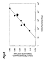
- the inventors investigated the relationship between the cooling rate and Rayleigh scattering coefficient in a part of optical fiber where the temperature was within the range from 1200 to 1700°C, which was higher than the lowest temperature (about 1200°C) at which the above-mentioned structural relaxation proceeded but not exceeding 1700°C at which the structural relaxation proceeded within a very short period of time.
- Fig. 8 exists between the cooling rate and Rayleigh scattering coefficient in a part of optical fiber where the temperature is 1200 to 1700°C.
- the present invention provides an apparatus for making an optical fiber for drawing an optical fiber preform upon heating and coating thus drawn optical fiber with a resin; the apparatus comprising a heating furnace, disposed between a drawing furnace for drawing the optical fiber preform upon heating and a resin coating section for coating the drawn optical fiber with the resin, for heating the drawn optical fiber such that the optical fiber attains a temperature within the range from 1200 to 1700°C, the heating furnace having a muffle tube through which the drawn optical fiber passes, the muffle tube being disposed at a position satisfying: L 1 ⁇ 0.2 ⁇ V where L1 is the distance (m) from the lower end of a heater in the drawing furnace to the upper end of the muffle tube; and V is the drawing rate (m/s).
- the heating furnace for heating the drawn optical fiber such that the optical fiber attains a temperature within the range from 1200 to 1700°C is disposed between the drawing furnace and resin coating section, the cooling rate is lowered in a predetermined segment of the part of optical fiber where the temperature is 1200 to 1700°C in the optical fiber drawn upon heating before being coated with the resin, whereby this part is annealed. Therefore, the optical fiber lowers its fictive temperature, whereby it becomes possible to make an optical fiber having decreased its transmission loss by reducing its Rayleigh scattering intensity during a period from the drawing upon heating to the resin coating.
- the heat treatment for reheating such as that in the above-mentioned prior art is unnecessary, whereby the apparatus is quite easily applicable to the mass production of optical fiber whose surfaces are coated with a resin.
- the muffle tube In the case where the drawing rate is higher, the position where the drawn optical fiber attains a given temperature shifts toward the resin coating section as compared with that in the case where the drawing rate is lower. Therefore, if the muffle tube is located at a position satisfying L 1 ⁇ 0.2 ⁇ V , then it can be placed at an appropriate position corresponding to the level of drawing rate, whereby the cooling rate of optical fiber can be lowered appropriately.
- the heating furnace may heat the drawn optical fiber at a temperature within the range from 1200 to 1600°C.
- the heating furnace heats the drawn optical fiber at a temperature within the range from 1200 to 1600°C
- the cooling rate of the optical fiber lowers in a predetermined segment in the part of optical fiber where the temperature is 1200 to 1700°C, so that the fictive temperature of the optical fiber decreases, whereby the Rayleigh scattering temperature can further be reduced.
- the temperature of heating furnace is that near the furnace center.
- the temperature of heater is set to about 1700°C in order for the temperature near the furnace center to become about 1600°C.
- the muffle tube may be disposed at a position where the drawn optical fiber attains a temperature within the range from 1400 to 1800°C when entering the muffle tube.
- the muffle tube is disposed at a position where the drawn optical fiber attains a temperature within the range from 1400 to 1800°C when entering the muffle tube, then it is placed at an appropriate position corresponding to the level of drawing rate, whereby the cooling rate of optical fiber can be lowered appropriately.
- the muffle tube may be formed so as to satisfy: L 2 ⁇ V /8 where L2 is the total length (m) of the muffle tube; and V is the drawing rate (m/s).
- L2 is the total length (m) of the muffle tube
- V is the drawing rate (m/s).
- the heating furnace may be provided with such a temperature gradient that the drawing furnace side and the resin coating section side attain higher and lower temperatures, respectively.
- the optical fiber drawn upon heating has such a temperature distribution that the temperature decreases from the drawing furnace side to the resin coating section side. Therefore, when the heating furnace is provided with such a temperature gradient that the drawing furnace side and the resin coating section side attain higher and lower temperatures, respectively, the heating furnace exhibits a temperature distribution corresponding to the optical fiber having the temperature distributionmentioned above, whereby the optical fiber can be cooled at a more appropriate cooling rate.
- the present invention provides a method of making an optical fiber comprising the steps of drawing an optical fiber preform upon heating and coating thus drawn optical fiber with a resin; wherein a segment of optical fiber yielding a temperature difference of at least 50°C in a part where the optical fiber before being coated with the resin attains a temperature of 1300 to 1700°C is cooled at a cooling rate of 1000°C/s or lower.
- the cooling rate in the segment of optical fiber yielding a temperature difference of at least 50°C in a part where the optical fiber before being coated with the resin attains a temperature of 1300 to 1700°C is set to 1000°C/s or lower, the fictive temperature of optical fiber lowers, so that the disorder in atomic arrangement is reduced, whereby it is possible to make an optical fiber having lowered its transmission loss by reducing the Rayleigh scattering intensity within a very short period from the drawing upon heating to the resin coating.
- the heat treatment for reheating such as that in the above-mentioned prior art is unnecessary, whereby the method is quite easily applicable to the mass production of optical fiber whose surfaces are coated with a resin.
- the method of making an optical fiber in accordance with the present invention may use, as the optical fiber preform, an optical fiber preform having a core portion exhibiting a relative refractive index difference of 0.001 or less with respect to pure silica glass in a state containing a dopant, and draw the optical fiber preform upon heating.
- the core portion is made of substantially pure silica glass exhibiting a relative refractive index difference of 0.001 or less with respect to pure silica glass in a state containing a dopant, the optical fiber further lowers its fictive temperature, whereby it is possible to further lower the Rayleigh scattering intensity.
- the method of making an optical fiber in accordance with the present invention may use, as the optical fiber preform, an optical fiberpreformwhose core portion is caused to contain hydroxyl group so as to yield a transmission loss of 0.02 to 0.5 dB/km due to hydroxyl group absorption at a wavelength of 1.38 ⁇ m, and draw the optical fiber preform upon heating.
- the optical fiber When hydroxyl group is contained such that the transmission loss caused by hydroxyl group absorption at a wavelength of 1.38 ⁇ m becomes at least 0.02 dB/km, the optical fiber further lowers its fictive temperature, whereby the Rayleigh scattering intensity can further be reduced.
- hydroxyl group is contained such that the transmission loss is greater than 0.5 dB/km, on the other hand, the loss increases due to the absorption by hydroxyl group, which cancels out the effect of reducing Rayleigh scattering intensity caused by the addition of hydroxyl group, whereby the transmission loss as a whole increases.
- the optical fiber when the core portion is caused to contain hydroxyl group so as to yield a transmission loss of 0.02 to 0.5 dB/km due to hydroxyl group absorption at a wavelength of 1.38 ⁇ m, the optical fiber further lowers its fictive temperature, whereby the Rayleigh scattering intensity can further be reduced.
- the method of making an optical fiber in accordance with the present invention may use, as the optical fiber preform, an optical fiber preformwhose core portion is caused to contain Cl so as to yield a relative refractive index difference of 0.0001 to 0.001 with respect to pure silica glass, and draw the optical fiber preform upon heating.
- the optical fiber When Cl is contained such that the relative refractive index difference with respect to pure silica glass is at least 0.0001, the optical fiber further lowers its fictive temperature, whereby the Rayleigh scattering intensity can further be lowered.
- Cl When Cl is contained such that the relative refractive index difference exceeds 0.001, the Rayleigh scattering intensity is enhanced by Cl itself, which cancels out the effect of lowering Rayleigh scattering intensity caused by the addition of Cl, whereby the total transmission loss increases. Therefore, when Cl is contained in the core portion such that the relative refractive index difference with respect to pure silica glass is 0.0001 to 0.001, the optical fiber further lowers its fictive temperature, whereby the Rayleigh scattering intensity can further be lowered.
- the method of making an optical fiber in accordance with the present invention may use, as the optical fiber preform, an optical fiber preform having a cladding portion whose part extending to the outermost periphery from a position where the distance from the center of the optical fiber preform is within the range from 0.7 to 0.9 in terms of the ratio with respect to the radius of the optical fiber preform is made of highly pure silica glass, and draw the optical fiber preform upon heating.
- the part unrelated to light transmission is a part where the distance from the center of the optical fiber preform is at least 0.7 in terms of the ratio with respect to the radius of optical fiber preform
- the transmission loss will be greater if the part on the outer periphery side of the position where the distance from the center is greater than 0.9 in terms of the ratio with respect to the radius of optical fiber preform is made of pure silica glass since the Rayleigh scattering intensity changes when the tension is made greater.
- the highly pure silica glass refers to silica glass whose relative refractive index difference with respect to pure silica glass in a state containing a dopant or the like is 0.001 or less.
- a part of the optical fiber having a temperature higher than 1700°C before being coated with the resin may be cooled at a cooling rate of 4000°C/s or higher.
- the height of equipment for carrying out drawing can be lowered. Since the structural relaxation of atoms proceeds in a very short period of time, the equilibrium state at each temperature can be maintained even when cooled at a cooling rate of 4000°C/s or higher, whereby no influence is exerted upon the Rayleigh scattering intensity.
- the present invention provides an apparatus for making an optical fiber for drawing an optical fiber preform upon heating and coating thus drawn optical fiber with a resin; the apparatus comprising a heating furnace, disposed between a drawing furnace for drawing the optical fiber preform upon heating and a resin coating section for coating the drawn optical fiber with the resin, for heating the drawn optical fiber such that a segment of the optical fiber yielding a temperature difference of at least 50°C in a part of the optical fiber attaining a temperature of 1300 to 1700°C is cooled at a cooling rate of 1000°C/s or less.
- the segment of optical fiber yielding a temperature difference of at least 50°C in the part of optical fiber before being coated with a resin where the temperature ranges from 1300 to 1700°C is slowly cooled at a cooling rate of 1000°C/s or less by the heating furnace disposed between the drawing furnace and the resin coating section, the optical fiber further lowers its fictive temperature, and the disorder in atomic arrangement is reduced, whereby it is possible to make an optical fiber having lowered its transmission loss by reducing the Rayleigh scattering intensity within a very short period from the drawing upon heating to the resin coating.
- the heat treatment for reheating such as that in the above-mentioned prior art is unnecessary, whereby the apparatus is quite easily applicable to the mass production of optical fiber whose surfaces are coated with a resin.
- the apparatus for making an optical fiber in accordance with the present invention may further comprise atmosphere gas supplying means for supplying, as an atmosphere gas of the optical fiber within the heating furnace, an atmosphere gas having a thermal conductivity on a par with or lower than that of an atmosphere gas in the drawing furnace.
- the atmosphere gas supplying means When the atmosphere gas supplying means is further provided, the atmosphere gas of optical fiber within the heating furnace lowers its thermal conductivity, so that the cooling rate within the heating furnace can be lowered, which enables the optical fiber to further lower its transmission loss.
- the apparatus for making an optical fiber in accordance with the present invention may further comprise outside diameter measuring means for measuring the outside diameter of the optical fiber having exited from the heating furnace, and control means for controlling the drawing rate of the optical fiber according to a result of measurement by the outside diameter measuring means such that the outside diameter of the optical fiber attains a predetermined value.
- the outside diameter of the optical fiber in which the outer diameter length is in a stable state is measured, and the drawing rate of optical fiber is controlled according to thus measured outside diameter, whereby the drawing rate of optical fiber can appropriately be controlled.
- Adrawing apparatus 1 is an apparatus for drawing silica type optical fiber; and comprises a drawing furnace 11, a heating furnace 21 for annealing, and a resin curing section 31, which are disposed in this order in the direction of drawing an optical fiber preform 2 (from the upper side to the lower side in Fig. 1).
- the optical fiber preform 2 held by a preform supplying apparatus (not depicted) is supplied to the drawing furnace 11, and the lower end of the optical fiber preform 2 is heated and softened by a heater 12 within the drawing furnace 11, so as to draw an optical fiber 3.
- An inert gas supply passage 15 from an inert gas supply section 14 is connected to a muffle tube 13 of the drawing furnace 11, so that an inert gas atmosphere is attained within the muffle tube 13 of drawing furnace 11.
- the optical fiber 3 drawn upon heating is rapidly cooled to about 1700°C by the inert gas within the muffle tube 13. Thereafter, the optical fiber 3 is taken out of the drawing furnace 11 from the lower part of the muffle tube 13, and is cooled with air between the drawing furnace 11 and the heating furnace 21.
- the inert gas N 2 gas can be used, for example.
- the air-cooled optical fiber 3 is sent to the heating furnace 21, so that a predetermined segment of the optical fiber 3 is heated and then is annealed at a predetermined cooling rate.
- the heating furnace 21 has a muffle tube 23 through which the optical fiber 3 passes.
- the muffle tube 23 is set such that its total length L2 (m) in the drawing direction of the optical fiber preform 2 (in the vertical direction of Fig. 1) satisfies: L 2 ⁇ V /8 where V is the drawing rate (m/s).
- the muffle tube 23 is set at a position where the temperature (entering temperature) of the optical fiber immediately before entering the muffle tube 23 falls within the range from 1400 to 1800°C, so as to satisfy, with respect to the drawing furnace 11, L 1 ⁇ 0.2 ⁇ V where L1 is the distance (m) from the lower end of heater 12 of drawing furnace 11 to the upper end of muffle tube 23; and Vis the drawing rate (m/s).
- the temperature of a heater 22 in the heating furnace 21 is set such that the temperature at the furnace center (the part through which the optical fiber 3 passes) attains a temperature within the range from 1200 to 1600°C, in particular within the range from 1300 to 1500°C.
- N 2 gas supply passage 25 Connected to the muffle tube 23 of heating furnace 21 is an N 2 gas supply passage 25 from an N 2 gas supply section 24, so that the muffle tube 23 of heating furnace 21 attains an N 2 gas atmosphere therewithin.
- N 2 gas gases having a relatively large molecular weight such as air and Ar, and the like can be used as well.
- an inert gas it is necessary to use an inert gas as a matter of course.
- the outside diameter is measured online by an outside diameter meter 41 acting as outside diameter measuring means, and thus measured value is fed back to a driving motor 43 for driving a drum 42 to rotate, such that the outside diameter is controlled so as to become constant.
- the output signal from the outside diameter meter 41 is sent to a control unit 44 acting as control means, where the rotating speed of drum 42 (driving motor 43) is determined by an arithmetic operation such that the outside diameter of optical fiber 3 attains a predetermined value which has been set beforehand.
- the output signal indicative of the rotating speed of drum 42 (driving motor 43) determined by the arithmetic operation is outputted from the control unit 44 to a driving motor driver (not depicted), whereas the driving motor driver controls the rotating speed of the driving motor 43 according to the output signal from the control unit 44.
- the optical fiber 3 is coated with a UV resin 52 by a coating die 51, and the UV resin 52 is cured by a UV lamp 32 of the resin curing section 31, whereby a coated optical fiber 4 is obtained.
- a coated optical fiber 4 is taken up by the drum 42.
- the drum 42 is supported by a rotary driving shaft 45, whereas an end part of the rotary driving shaft 45 is connected to the driving motor 43.
- the coating die 51 and the resin curing section 31 constitute the resin coating section in each claim.
- the resin coating section may be configured so as to apply a thermosetting resin, which is to be cured by a heating furnace.
- an N 2 gas supply section may be provided as the inert gas supply section 14 so as to supply N 2 gas into the muffle tube 13 such that an N 2 gas atmosphere is attained therein.
- the optical fiber 3 may be cooled to about 1000°C within the drawing furnace 11 (muffle tube 13) in an He gas atmosphere.
- N 2 gas is supplied into the muffle tube 13, so as to attain an N 2 gas atmosphere within the muffle tube 13, thereby causing the optical fiber 3 to attain a temperature of about 1700°C at the exit of drawing furnace 11 (muffle tube 13).
- He gas supply section and N 2 gas supply section may be provided, so as to supply He gas and/or N 2 gas into the muffle tube 13 in response to the drawing rate.
- the surface temperatures of the inner peripheral faces (surfaces opposing the surfaces of optical fiber preform 2 and optical fiber 3) of muffle tubes 13, 23 are taken as the temperatures of drawing furnace 11 and heating furnace 21, respectively.
- N 2 gas was used as the inert gas.
- Examples 1 to 4 are examples according to the apparatus and method for making an optical fiber in accordance with the above-mentioned first embodiment, whereas Comparative Examples 1 and 2 are comparative examples carried out for comparison with the examples according to the apparatus and method for making an optical fiber in accordance with the above-mentioned first embodiment.
- the optical fiber preform to be drawn had a core portion made of pure silica glass and a cladding portion made of fluorine-doped glass.
- the drawing rate, the drawing tension, and the temperature of heating furnace were set to 4 m/s, 0.196 N (20 gf), and 1300°C, respectively.
- the temperature of the optical fiber immediately before entering the heating furnace was 1600°C in terms of the surface temperature of optical fiber
- the temperature of the optical fiber immediately after exiting from the heating furnace was 1350°C in terms of the surface temperature of optical fiber.
- the part attaining a temperature of 1600 to 1350°C in the drawn optical fiber is assumed to have been cooled at an average annealing rate of about 2000°C/s in a segment of 0.5 m which is the total length of heating furnace.
- the optical fiber preform to be drawn had a core portion made of pure silica glass and a cladding portion made of fluorine-doped glass.
- the drawing rate, the drawing tension, and the temperature of heating furnace were set to 4 m/s, 0.196 N (20 gf), and 1300°C, respectively.
- the temperature of the optical fiber immediately before entering the heating furnace was 1600°C in terms of the surface temperature of optical fiber
- the temperature of the optical fiber immediately after exiting from the heating furnace was 1350°C in terms of the surface temperature of optical fiber.
- the part attaining a temperature of 1600 to 1350°C in the drawn optical fiber is assumed to have been cooled at an average annealing rate of about 1000°C/s in a segment of 1.0 m which is the total length of heating furnace.
- the optical fiber preform to be drawn had a core portion made of pure silica glass and a cladding portion made of fluorine-doped glass.
- the drawing rate, the drawing tension, and the temperature of heating furnace were set to 4 m/s, 0.196 N (20 gf), and 1300°C, respectively.
- the temperature of the optical fiber immediately before entering the heating furnace was 1600°C in terms of the surface temperature of optical fiber
- the temperature of the optical fiber immediately after exiting from the heating furnace was 1300°C in terms of the surface temperature of optical fiber.
- the part attaining a temperature of 1600 to 1300°C in the drawn optical fiber is assumed to have been cooled at an average annealing rate of about 600°C/s in a segment of 2.0 m which is the total length of heating furnace.
- the optical fiber preform to be drawn had a core portion made of pure silica glass and a cladding portion made of fluorine-doped glass.
- the drawing rate, the drawing tension, and the temperature of heating furnace were set to 4 m/s, 0.196 N (20 gf), and 1300°C, respectively.
- the temperature of the optical fiber immediately before entering the heating furnace was 1400°C in terms of the surface temperature of optical fiber
- the temperature of the optical fiber immediately after exiting from the heating furnace was 1300°C in terms of the surface temperature of optical fiber.
- the part attaining a temperature of 1400 to 1300°C in the drawn optical fiber is assumed to have been cooled at an average annealing rate of about 250°C/s in a segment of 1.0 m which is the total length of heating furnace.
- optical fiber was drawn in a state where the heating furnace was removed.
- the optical fiber preform to be drawn had a core portion made of pure silica glass and a cladding portion made of fluorine-doped glass.
- the drawing rate and the drawing tension were set to 2 to 10 m/s and 0.196 N (20 gf), respectively.
- the part of optical fiber attaining a temperature of 1300 to 1700°C was cooled at an annealing rate of about 5000°C/s.
- the transmission loss of drawn optical fiber was measured and found to be 0.168 dB/km, and there was no dependence on the drawing rate.
- the optical fiber preform to be drawn had a core portion made of pure silica glass and a cladding portion made of fluorine-doped glass.
- the drawing rate, the drawing tension, and the temperature of heating furnace were set to 4 m/s, 0.196 N (20 gf), and 1300°C, respectively. In this case, the temperature of the optical fiber immediately before entering the heating furnace (entering temperature) was 1000°C in terms of the surface temperature of optical fiber.
- the transmission loss with respect to light having a wavelength of 1.55 ⁇ m is 0.164 to 0.167 dB/km in Examples 1 to 4, and thus can be lowered by the range of 0.001 to 0.004 dB/km from the transmission loss of 0.168 dB with respect to light having a wavelength of 1.55 ⁇ m in Comparative Examples 1 and 2.
- L1 as the position of muffle tube of heating furnace is made greater than 0.8 m (so as to be distanced from the drawing furnace) when the drawing rate is 4 m/s, it will be harder to heat the part of optical fiber attaining a temperature of 1200 to 1700°C after drawing, so that the cooling rate in this part cannot be lowered, whereby the transmission loss will increase.
- Examples 5 and 6 are examples according to the apparatus and method for making an optical fiber in accordance with the above-mentioned first embodiment
- Comparative Example 3 is a comparative example carried out for comparison with the examples according to the apparatus and method for making an optical fiber in accordance with the above-mentioned first embodiment.
- the optical fiber preform to be drawn had a core portion made of pure silica glass and a cladding portion made of fluorine-doped glass.
- the drawing rate, the drawing tension, and the temperature of heating furnace were set to 4 m/s, 0.196 N (20 gf), and 1500°C, respectively.
- the temperature of the optical fiber immediately before entering the heating furnace was 1600°C in terms of the surface temperature of optical fiber
- the temperature of the optical fiber immediately after exiting from the heating furnace was 1530°C in terms of the surface temperature of optical fiber.
- the part attaining a temperature of 1600 to 1530°C in the drawn optical fiber is assumed to have been cooled at an average annealing rate of about 280°C/s in a segment of 1.0 m which is the total length of heating furnace.
- the optical fiber preform to be drawn had a core portion made of pure silica glass and a cladding portion made of fluorine-doped glass.
- the drawing rate, the drawing tension, and the temperature of heating furnace were set to 4 m/s, 0.196 N (20 gf), and 1200°C, respectively.
- the temperature of the optical fiber immediately before entering the heating furnace was 1600°C in terms of the surface temperature of optical fiber
- the temperature of the optical fiber immediately after exiting from the heating furnace was 1250°C in terms of the surface temperature of optical fiber.
- the part attaining a temperature of 1600 to 1250°C in the drawn optical fiber is assumed to have been cooled at an average annealing rate of about 350°C/s in a segment of 1.0 m which is the total length of heating furnace.
- the optical fiber preform to be drawn had a core portion made of pure silica glass and a cladding portion made of fluorine-doped glass.
- the drawing rate, the drawing tension, and the temperature of heating furnace were set to 4 m/s, 0.196 N (20 gf), and 1000°C, respectively.
- the temperature of the optical fiber immediately before entering the heating furnace was 1600°C in terms of the surface temperature of optical fiber
- the temperature of the optical fiber immediately after exiting from the heating furnace was 1050°C in terms of the surface temperature of optical fiber.
- the part attaining a temperature of 1600 to 1050°C in the drawn optical fiber is assumed to have been cooled at an average annealing rate of about 2200°C/s in a segment of 1.0 m which is the total length of heating furnace.
- the transmission loss with respect to light having a wavelength of 1.55 ⁇ m is 0.162 to 0.167 dB/km in Examples 5 to 6, and thus can be lowered by the range of 0.001 to 0.006 dB/km from the transmission loss of 0.168 dB with respect to light having a wavelength of 1.55 ⁇ m in Comparative Example 3.
- the temperature of heating furnace surface temperature of inner peripheral face of muffle tube
- the part of optical fiber attaining a temperature of 1300 to 1700°C after drawing can be heated, so that the cooling rate in this part is lowered, whereby the transmission can be reduced.
- the transmission loss can further be reduced when the temperature of the heating furnace (surface temperature of inner peripheral face of muffle tube) is 1300 to 1500°C.
- Examples 7 and 8 are examples according to the apparatus and method for making an optical fiber in accordance with the above-mentioned first embodiment
- Comparative Example 4 is a comparative example carried out for comparison with the examples according to the apparatus and method for making an optical fiber in accordance with the above-mentioned first embodiment.
- the optical fiber preform to be drawn had a core portion made of pure silica glass and a cladding portion made of fluorine-doped glass.
- the drawing rate, the drawing tension, and the temperature of heating furnace were set to 8 m/s, 0.196 N (20 gf), and 1300°C, respectively.
- the temperature of the optical fiber immediately before entering the heating furnace was 1700°C in terms of the surface temperature of optical fiber
- the temperature of the optical fiber immediately after exiting from the heating furnace was 1550°C in terms of the surface temperature of optical fiber.
- the part attaining a temperature of 1700 to 1550°C in the drawn optical fiber is assumed to have been cooled at an average annealing rate of about 1200°C/s in a segment of 1.0 m which is the total length of heating furnace.
- the optical fiber preform to be drawn had a core portion made of pure silica glass and a cladding portion made of fluorine-doped glass.
- the drawing rate, the drawing tension, and the temperature of heating furnace were set to 8 m/s, 0.196 N (20 gf), and 1300°C, respectively.
- the temperature of the optical fiber immediately before entering the heating furnace was 1700°C in terms of the surface temperature of optical fiber
- the temperature of the optical fiber immediately after exiting from the heating furnace was 1450°C in terms of the surface temperature of optical fiber.
- the part attaining a temperature of 1700 to 1450°C in the drawn optical fiber is assumed to have been cooled at an average annealing rate of about 1000°C/s in a segment of 2.0 m which is the total length of heating furnace.
- the optical fiber preform to be drawn had a core portion made of pure silica glass and a cladding portion made of fluorine-doped glass.
- the drawing rate, the drawing tension, and the temperature of heating furnace were set to 8 m/s, 0.196 N (20 gf), and 1300°C, respectively. In this case, the temperature of the optical fiber immediately before entering the heating furnace (entering temperature) was 1000°C in terms of the surface temperature of optical fiber.
- the transmission loss with respect to light having a wavelength of 1.55 ⁇ m is 0.165 to 0.167 dB/km in Examples 7 and 8, and thus can be lowered by the range of 0.001 to 0.003 dB/km from the transmission loss of 0.168 dB with respect to light having a wavelength of 1.55 ⁇ m in Comparative Example 4.
- L1 as the position of muffle tube of heating furnace is 2.0 m when the drawing rate is 8 m/s, it will be harder to heat the part of optical fiber attaining a temperature of 1200 to 1700°C after drawing, so that the cooling rate in this part cannot be lowered, whereby the transmission loss will increase.
- cooling rate is lowered in a predetermined segment in the part attaining a temperature ranging from 1200 to 1700°C in the above-mentioned optical fiber 3, so that the fictive temperature of optical fiber 3 decreases, thus lowering the disorder in atomic arrangement, whereby it becomes possible to make the optical fiber 3 having decreased its transmission loss by reducing its Rayleigh scattering intensity during the period from the drawing upon heating to the coating with the UV resin 52.
- the heat treatment for reheating such as that in the above-mentioned prior art is unnecessary, whereby the apparatus is quite easily applicable to the mass production of the coated optical fiber 4 whose surface is coated with the UV resin 52 cured thereon.
- the cooling rate of optical fiber 3 decreases at a predetermined segment in the part of optical fiber 3 attaining a temperature of 1200 to 1700°C, so that the optical fiber 3 lowers its fictive temperature, whereby its Rayleigh scattering intensity can further be reduced.
- the cooling rate within the heating furnace 21 can be lowered, whereby the optical fiber 3 can further lower its transmission loss.
- the cooling rate of optical fiber 3 within the drawing furnace (muffle tube 13) becomes about 30000°C/s.
- the cooling rate of optical fiber 3 becomes 4000 to 5000°C/s, so that the optical fiber preform 2 is softened upon heating and is rapidly cooled until it tapers down to a predetermined diameter, whereby the optical fiber 3 can be restrained from fluctuating its outside diameter.
- the part of optical fiber 3 yielding a temperature higher than 1700°C before entering the heating furnace 21 is cooled at a cooling rate of 4000°C/s or higher, whereby the height of equipment needed for cooling the optical fiber 3 can be reduced.
- the fictive temperature will be lower than 1700°C even when rapidly cooled at a rate of about 30000°C/s, for example, thus exerting no influences on Rayleigh scattering.
- the outside diameter meter 41 for measuring the outside diameter of optical fiber 3 having exited from the heating furnace 21 and the control unit 44 for controlling the rotating speed of drum 42 (driving motor 43) according to the output signal from the outside diameter meter 41 such that the outside diameter of optical fiber 3 attains a predetermined value are provided, the outside diameter of the optical fiber 3 having exited from the heating furnace 21 with an outside diameter length in a stable state is measured, and the rotating speed of the drum 42 (driving motor 43) is controlled according to this stable outside diameter, whereby the drawing rate of optical fiber 3 can be controlled appropriately.
- the heater 22 of heating furnace 21 includes a first heater 71, a second heater 72, and a third heater 73.
- the heaters 71, 72, 73 are successively disposed in this order in the direction of drawing the optical fiber preform 2 (from the upper side to lower side in Fig. 2).
- T 1 T 2+25°C
- T 3 T 2-25°C
- T1 is the surface temperature of inner peripheral face of muffle tube 23 at a position corresponding to the first heater 71
- T2 is the surface temperature of inner peripheral face of muffle tube 23 at a position corresponding to the second heater 72
- T3 is the surface temperature of inner peripheral face of muffle tube 23 at a position corresponding to the third heater 73.
- the difference between T1 and T2 or the difference between T2 and T3 is not limited to 25°C mentioned above, and the temperature difference may be about 30°C, for example.
- a temperature gradient yielding higher and lower temperatures on the drawing furnace 11 side and the resin coating section 31 (coating die 51) side, respectively, is provided within the muffle tube 23 of heating furnace 21 when the first heater 71, second heater 72, and third heater 73 are provided.
- the optical fiber 3 drawn upon heating in the drawing furnace 11 has such a temperature distribution that its temperature lowers from the drawing furnace 11 side to the resin coating section 31 (coating die 51) side.
- the heating furnace 21 is provided with such a temperature gradient that higher and lower temperatures are attained on the drawing furnace 11 side and the resin coating section 31 (coating die 51) side, respectively, so that the muffle tube 23 has a temperature distribution corresponding to the temperature of optical fiber 3 therewithin and appropriately keeps its temperature difference from the optical fiber 3, whereby the optical fiber 3 can be cooled at a further appropriate cooling rate.
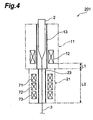
- the heating furnace 21 may be provided integrally with the drawing furnace 11 so as to be continuous therewith as in the drawing apparatus 201 shown in Fig. 4.
- the cooling rate decreases in a predetermined segment in the part yielding a temperature of 1200 to 1700°C in the optical fiber 3 after drawing upon heating in the drawing furnace 11 before being coated with the UV resin 52, so that the optical fiber 3 lowers its fictive temperature, and the disorder in atomic arrangement is reduced, whereby it is possible to make the optical fiber 3 having lowered its transmission loss by reducing the Rayleigh scattering intensity within a very short period from the drawing upon heating to the coating with the UV resin 52.
- a drawing apparatus 301 is a drawing apparatus for a silica type optical fiber; and comprises a drawing furnace 11, a heating furnace 21 for annealing, and a resin curing section 31, which are disposed in this order in the direction of drawing an optical fiber preform 2 (from the upper side to the lower side in Fig. 5).
- the optical fiber preform 2 held by a preform supplying apparatus (not depicted) is supplied to the drawing furnace 11, and the lower end of the optical fiber preform 2 is heated and softened by a heater 12 within the drawing furnace 11, so as to draw an optical fiber 3.
- He gas/N 2 gas supply passage 315 for selectively supplying He gas or N 2 gas from He gas/N 2 gas supply section 314 is connected to a muffle tube 13 of the drawing furnace 11, so that an He gas atmosphere or N 2 gas atmosphere is attained within the muffle tube 13 of drawing furnace 11.
- the optical fiber 3 drawn upon heating is rapidly cooled to about 1700°C within the muffle tube 13. Thereafter, the optical fiber 3 is taken out of the drawing furnace 11 from the lower part of the muffle tube 13, and is cooled with air between the drawing furnace 11 and the heating furnace 21.
- the air-cooled optical fiber 3 is sent to the heating furnace 21, so that a predetermined segment of optical fiber 3 is heated and then is annealed at a predetermined cooling rate.
- the annealing in the heating furnace 21 is carried out by cooling at a cooling rate of 1000°C/s or less the segment where the optical fiber 3 yields a temperature difference of at least 50°C in the part attaining a temperature of 1300 to 1700°C in the optical fiber 3 drawn upon heating.
- the installing positions of the heater 22 and muffle tube 23 of heating furnace 21 and the total length thereof in the drawing direction of optical fiber preform 2 are set in view of the drawing rate.
- the drawing rate is needed to be taken into consideration, since the position at which the optical fiber 3 attains a given temperature descends as the drawing rate increases.
- the temperature of heater 22 of heating furnace 21 is set such that the segment where the optical fiber 3 located within the muffle tube 23 attains a temperature difference of at least 50°C is cooled at a cooling rate of 1000°C/s or less.
- N 2 gas has a thermal conductivity lower than that of He gas, thereby acting to lower the cooling rate of optical fiber.
- gases having a relatively large molecular weight such as air and Ar, and the like can be used as well.
- the difference between the surface temperature of optical fiber 3 and the temperature within the optical fiber 3 is on the order of 20 to 100°C.
- the surface temperatures of the inner peripheral faces (surfaces opposing the surfaces of optical fiber preform 2 and optical fiber 3) of muffle tubes 13, 23 are taken as the temperatures of drawing furnace 11 and heating furnace 21, respectively.
- Examples 9 to 12 are examples according to the apparatus and method for making an optical fiber in accordance with the above-mentioned second embodiment, whereas Comparative Examples 5 to 7 are comparative examples carried out for comparison with the examples according to the apparatus and method for making an optical fiber in accordance with the above-mentioned second embodiment.
- the heating furnace having a muffle tube with a total length (L2) of 2 m in the drawing direction of optical fiber preform (and an inner peripheral diameter of about 30mm), an optical fiber was drawn. Supplied into the drawing furnace (muffle tube) was N 2 gas.
- the optical fiber preform to be drawn had a core portion made of pure silica glass and a cladding portion made of fluorine-doped glass.
- the drawing rate, the drawing tension, and the temperature of heating furnace were set to 100 m/min, 0.196 N (20 gf), and 1400°C, respectively.
- the temperature of the optical fiber immediately before entering the heating furnace was 1700°C in terms of the surface temperature of optical fiber
- the temperature of the optical fiber immediately after exiting from the heating furnace was 1450°C in terms of the surface temperature of optical fiber.
- the part attaining a temperature of 1450 to 1700°C in the drawn optical fiber is assumed to have been cooled at an average cooling rate of about 250°C/s in a segment of 2 m which is the total length of heating furnace.
- the transmission loss (transmission loss with respect to light having a wavelength of 1.55 ⁇ m) of the drawn optical fiber was measured and found to be 0.165 dB/km.
- the Rayleigh scattering coefficient determined from the measured data of wavelength characteristic of transmission loss was 0.825 dB ⁇ m 4 /km.
- the heating furnace having a muffle tube with a total length (L2) of 2 m in the drawing direction of optical fiber preform (and an inner peripheral diameter of about 30mm), an optical fiber was drawn. Supplied into the drawing furnace (muffle tube) was He gas.
- the optical fiber preform to be drawn had a core portion made of pure silica glass and a cladding portion made of fluorine-doped glass.
- the drawing rate, the drawing tension, and the temperature of heating furnace were set to 400 m/min, 0.294 N (30 gf), and 1200°C, respectively.
- the temperature of the optical fiber immediately before entering the heating furnace was 1550°C in terms of the surface temperature of optical fiber
- the temperature of the optical fiber immediately after exiting from the heating furnace was 1300°C in terms of the surface temperature of optical fiber.
- the part attaining a temperature of 1300 to 1550°C in the drawn optical fiber is assumed to have been cooled at an average cooling rate of about 1000°C/s in a segment of 2 m which is the total length of heating furnace.
- the transmission loss (transmission loss with respect to light having a wavelength of 1.55 ⁇ m) of the drawn optical fiber was measured and found to be 0.167 dB/km.
- the Rayleigh scattering coefficient determined from the measured data of wavelength characteristic of transmission loss was 0.838 dB ⁇ m 4 /km.
- the heating furnace having a muffle tube with a total length (L2) of 0.5 m in the drawing direction of optical fiber preform (and an inner peripheral diameter of about 30 mm), an optical fiber was drawn. Supplied into the drawing furnace (muffle tube) was N 2 gas.
- the optical fiber preform to be drawn had a core portion made of pure silica glass and a cladding portion made of fluorine-doped glass.
- the drawing rate, the drawing tension, and the temperature of heating furnace were set to 100 m/min, 0.245 N (25 gf), and 1450°C, respectively.
- the temperature of the optical fiber immediately before entering the heating furnace was 1550°C in terms of the surface temperature of optical fiber
- the temperature of the optical fiber immediately after exiting from the heating furnace was 1500°C in terms of the surface temperature of optical fiber.
- the part attaining a temperature of 1500 to 1550°C in the drawn optical fiber is assumed to have been cooled at an average cooling rate of about 250°C/s in a segment of 0.5 m which is the total length of heating furnace.
- the transmission loss (transmission loss with respect to light having a wavelength of 1.55 ⁇ m) of the drawn optical fiber was measured and found to be 0.166 dB/km.
- the Rayleigh scattering coefficient determined from the measured data of wavelength characteristic of transmission loss was 0.838 dB ⁇ m 4 /km.
- the heating furnace having a muffle tube with a total length (L2) of 2 m in the drawing direction of optical fiber preform (and an inner peripheral diameter of about 30mm), an optical fiber was drawn. Supplied into the drawing furnace (muffle tube) was N 2 gas.
- the optical fiber preform to be drawn had a core portion made of pure silica glass and a cladding portion made of fluorine-doped glass.
- the drawing rate, the drawing tension, and the temperature of heating furnace were set to 30 m/min, 0.196 N (20 gf), and 1400°C, respectively.
- the temperature of the optical fiber immediately before entering the heating furnace was 1700°C in terms of the surface temperature of optical fiber
- the temperature of the optical fiber immediately after exiting from the heating furnace was 1420°C in terms of the surface temperature of optical fiber.
- the part attaining a temperature of 1420 to 1700°C in the drawn optical fiber is assumed to have been cooled at an average cooling rate of about 90°C/s in a segment of 2 m which is the total length of heating furnace.
- the transmission loss (transmission loss with respect to light having a wavelength of 1.55 ⁇ m) of the drawn optical fiber was measured and found to be 0.160 dB/km.
- the Rayleigh scattering coefficient determined from the measured data of wavelength characteristic of transmission loss was 0.805 dB ⁇ m 4 /km.
- optical fiber was drawn in a state where the heating furnace was removed. Supplied into the drawing furnace (muffle tube) was He gas.
- the optical fiber preform to be drawn had a core portion made of pure silica glass and a cladding portion made of fluorine-doped glass.
- the drawing rate and the drawing tension were set to 100 m/min and 0.294 N (30 gf), respectively. In this case, the part attaining a temperature of 1300 to 1700°C in the optical fiber was cooled at an average cooling rate of about 30000°C/s.
- the transmission loss (transmission loss with respect to light having a wavelength of 1.55 ⁇ m) of the drawn optical fiber was measured and found to be 0.175 dB/km.
- the Rayleigh scattering coefficient determined from the measured data of wavelength characteristic of transmission loss was 0.88 dB ⁇ m 4 /km.
- optical fiber was drawn in a state where the heating furnace was removed. Supplied into the drawing'furnace (muffle tube) was He gas.
- the optical fiber preform to be drawn had a core portion made of pure silica glass and a cladding portion made of fluorine-doped glass.
- the drawing rate and the drawing tension were set to 100 m/min and 0.196 N (20 gf), respectively. In this case, the part attaining a temperature of 1300 to 1700°C in the optical fiber was cooled at an average cooling rate of about 5000°C/s.
- the transmission loss (transmission loss with respect to light having a wavelength of 1.55 ⁇ m) of the drawn optical fiber was measured and found to be 0.170 dB/km.
- the Rayleigh scattering coefficient determined from the measured data of wavelength characteristic of transmission loss was 0.85 dB ⁇ m 4 /km.
- the heating furnace having a muffle tube with a total length (L2) of 2 m in the drawing direction of optical fiber preform (and an inner peripheral diameter of about 30mm), an optical fiber was drawn. Supplied into the drawing furnace (muffle tube) was N 2 gas.
- the optical fiber preform to be drawn had a core portion made of pure silica glass and a cladding portion made of fluorine-doped glass.
- the drawing rate, the drawing tension, and the temperature of heating furnace were set to 100 m/min, 0.294 N (30 gf), and 900°C, respectively.
- the temperature of the optical fiber immediately before entering the heating furnace was 1300°C in terms of the surface temperature of optical fiber
- the temperature of the optical fiber immediately after exiting from the heating furnace was 1000°C in terms of the surface temperature of optical fiber.
- the part attaining a temperature of 1000 to 1300°C in the drawn optical fiber is assumed to have been cooled at an average cooling rate of about 250°C/s in a segment of 2 m which is the total length of heating furnace.
- the transmission loss (transmission loss with respect to light having a wavelength of 1.55 ⁇ m) of the drawn optical fiber was measured and found to be 0.170 dB/km.
- the Rayleigh scattering coefficient determined from the measured data of wavelength characteristic of transmission loss was 0.85 dB ⁇ m 4 /km.
- Examples 9 to 12 exhibited a Rayleigh scattering coefficient of 0.805 to 0.838 dB ⁇ m 4 /km and a transmission loss of 0.160 to 0.167 dB/km with respect to light having a wavelength of 1.55 ⁇ m, thus being able to lower the Rayleigh scattering coefficient and reduce the transmission loss as compared with Comparative Examples 5 to 7 yielding a Rayleigh scattering coefficient of 0.85 to 0.88 dB ⁇ m 4 /km and a transmission loss of 0.170 to 0.175 dB/km with respect to light having a wavelength of 1.55 ⁇ m.
- Examples 13 and 14 are examples of the apparatus and method for making an optical fiber in accordance with the above-mentioned second embodiment.
- the core portion of the optical fiber preform to be drawn was caused to contain hydroxyl group such that the transmission loss by hydroxyl group absorption at a wavelength of 1.38 ⁇ m became 0.02 dB/km.
- Supplied into the drawing furnace (muffle tube) was N 2 gas.
- a heating furnace having a muffle tube with a total length (L2) of 2 m (and an inner peripheral diameter of about 30 mm) was used, whereas the drawing rate, the drawing tension, and the temperature of heating furnace (surface temperature at the inner peripheral face of muffle tube) were set to 100 m/min, 0.196 N (20 gf), and 1400°C, respectively.
- the temperature of the optical fiber immediately before entering the heating furnace was 1700°C in terms of the surface temperature of optical fiber
- the temperature of the optical fiber immediately after exiting from the heating furnace was 1450°C in terms of the surface temperature of optical fiber.
- the part attaining a temperature of 1450 to 1700°C in the drawn optical fiber is assumed to have been cooled at an average cooling rate of about 250°C/s in a segment of 2 m which is the total length of heating furnace.
- the transmission loss (transmission loss with respect to light having a wavelength of 1.55 ⁇ m) of the drawn optical fiber was measured and found to be 0.164 dB/km.
- the Rayleigh scattering coefficient determined from the measured data of wavelength characteristic of transmission loss was 0.82 dB ⁇ m 4 /km.
- the core portion of the optical fiber preform to be drawn was caused to contain hydroxyl group such that the transmission loss by hydroxyl group absorption at a wavelength of 1.38 ⁇ m became 0.5 dB/km.
- Supplied into the drawing furnace (muffle tube) was N 2 gas.
- a heating furnace. having a muffle tube with a total length (L2) of 2 m (and an inner peripheral diameter of about 30 mm) was used, whereas the drawing rate, the drawing tension, and the temperature of heating furnace (surface temperature at the inner peripheral face of muffle tube) were set to 100 m/min, 0.196 N (20 gf), and 1400°C, respectively.
- the temperature of the optical fiber immediately before entering the heating furnace was 1700°C in terms of the surface temperature of optical fiber
- the temperature of the optical fiber immediately after exiting from the heating furnace was 1450°C in terms of the surface temperature of optical fiber.
- the part attaining a temperature of 1450 to 1700°C in the drawn optical fiber is assumed to have been cooled at an average cooling rate of about 250°C/s in a segment of 2 m which is the total length of heating furnace.
- the transmission loss (transmission loss with respect to light having a wavelength of 1.55 ⁇ m) of the drawn optical fiber was measured and found to be 0.165 dB/km.
- the Rayleigh scattering coefficient determined from the measured data of wavelength characteristic of transmission loss was 0.815 dB ⁇ m 4 /km.
- Examples 13 and 14 exhibited a Rayleigh scattering coefficient of 0.815 to 0.82 dB ⁇ m 4 /km and a transmission loss of 0.164 to 0.165 dB/km with respect to light having a wavelength of 1.55 ⁇ m, thus being able to lower the Rayleigh scattering coefficient and reduce the transmission loss as compared with Example 9 yielding a Rayleigh scattering coefficient of 0.825 dB ⁇ m 4 /km and a transmission loss of 0.165 dB/km with respect to light having a wavelength of 1.55 ⁇ m.
- Example 14 in which hydroxyl group is contained in the core portion of the optical fiber preform to be drawn such that the transmission loss caused by hydroxyl group absorption at a wavelength of 1.38 ⁇ m is 0.5 dB/km, yields a Rayleigh scattering coefficient lower than that in Example 9, the transmission loss caused by hydroxyl group absorption therein is at a level which cannot be neglected, thus canceling out the effect of lowering the Rayleigh scattering coefficient, whereby transmission loss will be enhanced if hydroxyl group is contained more.
- Examples 15 to 17 are examples of the apparatus and method for making an optical fiber in accordance with the above-mentioned second embodiment.
- the core portion of the optical fiber preform to be drawn was caused to contain Cl such that the relative refractive index difference with respect to pure silica glass became 0.0001.
- Supplied into the drawing furnace (muffle tube) was N 2 gas.
- a heating furnace having a muffle tube with a total length (L2) of 2 m (and an inner peripheral diameter of about 30 mm) was used, whereas the drawing rate, the drawing tension, and the temperature of heating furnace (surface temperature at the inner peripheral face of muffle tube) were set to 100 m/min, 0.196 N (20 gf), and 1400°C, respectively.
- the temperature of the optical fiber immediately before entering the heating furnace was 1700°C in terms of the surface temperature of optical fiber
- the temperature of the optical fiber immediately after exiting from the heating furnace was 1450°C in terms of the surface temperature of optical fiber.
- the part attaining a temperature of 1450 to 1700°C in the drawn optical fiber is assumed to have been cooled at an average cooling rate of about 250°C/s in a segment of 2 m which is the total length of heating furnace.
- the transmission loss (transmission loss with respect to light having a wavelength of 1.55 ⁇ m) of the drawn optical fiber was measured and found to be 0.164 dB/km.
- the Rayleigh scattering coefficient determined from the measured data of wavelength characteristic of transmission loss was 0.82 dB ⁇ m 4 /km.
- the core portion of the optical fiber preform to be drawn was caused to contain Cl such that the relative refractive index difference with respect to pure silica glass became 0.0005.
- Supplied into the drawing furnace (muffle tube) was N 2 gas.
- a heating furnace having a muffle tube with a total length (L2) of 2 m (and an inner peripheral diameter of about 30 mm) was used, whereas the drawing rate, the drawing tension, and the temperature of heating furnace (surface temperature at the inner peripheral face of muffle tube) were set to 100 m/min, 0.196 N (20 gf), and 1400°C, respectively.
- the temperature of the optical fiber immediately before entering the heating furnace was 1700°C in terms of the surface temperature of optical fiber
- the temperature of the optical fiber immediately after exiting from the heating furnace was 1450°C in terms of the surface temperature of optical fiber.
- the part attaining a temperature of 1450 to 1700°C in the drawn optical fiber is assumed to have been cooled at an average cooling rate of about 250°C/s in a segment of 2 m which is the total length of heating furnace.
- the transmission loss (transmission loss with respect to light having a wavelength of 1.55 ⁇ m) of the drawn optical fiber was measured and found to be 0.163 dB/km.
- the Rayleigh scattering coefficient determined from the measured data of wavelength characteristic of transmission loss was 0.815 dB ⁇ m 4 /km.
- the core portion of the optical fiber preform to be drawn was caused to contain Cl such that the relative refractive index difference with respect to pure silica glass became 0.001.
- Supplied into the drawing furnace (muffle tube) was N 2 gas.
- a heating furnace having a muffle tube with a total length (L2) of 2 m (and an inner peripheral diameter of about 30 mm) was used, whereas the drawing rate, the drawing tension, and the temperature of heating furnace (surface temperature at the inner peripheral face of muffle tube) were set to 100 m/min, 0.196 N (20 gf), and 1400°C, respectively.
- the temperature of the optical fiber immediately before entering the heating furnace was 1700°C in terms of the surface temperature of optical fiber
- the temperature of the optical fiber immediately after exiting from the heating furnace was 1450°C in terms of the surface temperature of optical fiber.
- the part attaining a temperature of 1450 to 1700°C in the drawn optical fiber is assumed to have been cooled at an average cooling rate of about 250°C/s in a segment of 2 m which is the total length of heating furnace.
- the transmission loss (transmission loss with respect to light having a wavelength of 1.55 ⁇ m) of the drawn optical fiber was measured and found to be 0.165 dB/km.
- the Rayleigh scattering coefficient determined from the measured data of wavelength characteristic of transmission loss was 0.825 dB ⁇ m 4 /km.
- Examples 15 to 17 exhibited a Rayleigh scattering coefficient of 0.815 to 0.825 dB ⁇ m 4 /km and a transmission loss of 0.163 to 0.165 dB/km with respect to light having a wavelength of 1.55 ⁇ m, thus being able to lower the Rayleigh scattering coefficient and reduce the transmission loss as compared with Example 9 yielding a Rayleigh scattering coefficient of 0.825 dB ⁇ m 4 /km and a transmission loss of 0.165 dB/km with respect to light having a wavelength of 1.55 ⁇ m.
- Example 17 in which the core portion of the optical fiber preform to be drawn is caused to contain Cl such that the relative refractive index difference with respect to pure silica glass becomes 0.001, yields the results identical to those of Example 9, so that the decrease in Rayleigh scattering intensity caused by the drop in fictive temperature due to Cl contained therein and the increase in Rayleigh scattering intensity caused by Cl itself cancel out each other, whereby transmission loss will increase if Cl is contained more.
- Examples 18 and 19 are examples according to the apparatus and method for making an optical fiber in accordance with the above-mentioned second embodiment, whereas Comparative Examples 8 to 9 are comparative examples carried out for comparison with the examples according to the apparatus and method for making an optical fiber in accordance with the above-mentioned second embodiment. As shown in Figs.
- the optical fiber preform 402 used in the following experiments is constituted by a core portion 412 made of pure silica glass (refractive index n1), a first cladding portion 422 made of fluorine-doped glass (refractive index n2), and a second cladding portion 432 made of pure silica glass (refractive index n1).
- the first cladding portion 422 has a region extending from the outer periphery of core portion 412 to a radius a, thus yielding an outside diameter 2a.
- the second cladding region 432 has a region extending from the outer periphery of first cladding portion 422 to a radius d (outer periphery) , thus yielding an outside diameter 2d.
- d outer periphery
- highlypure silica glass may be used in place of pure silica glass.
- Supplied into the drawing furnace (muffle tube) was N 2 gas.
- a heating furnace having a muffle tube with a total length (L2) of 2 m (and an inner peripheral diameter of about 30 mm) was used for drawing an optical fiber.
- the drawing rate, the drawing tension, and the temperature of heating furnace were set to 100m/min, 0.490N (50 gf), and 1450°C, respectively.
- the temperature of the optical fiber immediately before entering the heating furnace was 1700°C in terms of the surface temperature of optical fiber
- the temperature of the optical fiber immediately after exiting from the heating furnace was 1450°C in terms of the surface temperature of optical fiber.
- the part attaining a temperature of 1450 to 1700°C in the drawn optical fiber is assumed to have been cooled at an average cooling rate of about 250°C/s in a segment of 2 m which is the total length of heating furnace.
- the transmission loss (transmission loss with respect to light having a wavelength of 1.55 ⁇ m) of the drawn optical fiber was measured and found to be 0.164 dB/km.
- the Rayleigh scattering coefficient determined from the measured data of wavelength characteristic of transmission loss was 0.825 dB ⁇ m 4 /km.
- Supplied into the drawing furnace was N 2 gas.
- a heating furnace having a muffle tube with a total length (L2) of 2 m (and an inner peripheral diameter of about 30 mm) was used for drawing an optical fiber.
- the drawing rate, the drawing tension, and the temperature of heating furnace were set to 100m/min, 0.490N (50 gf), and 1450°C, respectively.
- the temperature of the optical fiber immediately before entering the heating furnace was 1700°C in terms of the surface temperature of optical fiber
- the temperature of the optical fiber immediately after exiting from the heating furnace was 1450°C in terms of the surface temperature of optical fiber.
- the part attaining a temperature of 1450 to 1700°C in the drawn optical fiber is assumed to have been cooled at an average cooling rate of about 250°C/s in a segment of 2 m which is the total length of heating furnace.
- the transmission loss (transmission loss with respect to light having a wavelength of 1.55 ⁇ m) of the drawn optical fiber was measured and found to be 0.166 dB/km.
- the Rayleigh scattering coefficient determined from the measured data of wavelength characteristic of transmission loss was 0.835 dB ⁇ m 4 /km.
- Supplied into the drawing furnace (muffle tube) was N 2 gas.
- Aheating furnace having a muffle tube with a total length (L2) of 2 m (and an inner peripheral diameter of about 30 mm) was used for drawing an optical fiber.
- the drawing rate, the drawing tension, and the temperature of heating furnace were set to 100 m/min, 0.490 N (50 gf), and 1450°C, respectively.
- the temperature of the optical fiber immediately before entering the heating furnace was 1700°C in terms of the surface temperature of optical fiber
- the temperature of the optical fiber immediately after exiting from the heating furnace was 1450°C in terms of the surface temperature of optical fiber.
- the part attaining a temperature of 1450 to 1700°C in the drawn optical fiber is assumed to have been cooled at an average cooling rate of about 250°C/s in a segment of 2 m which is the total length of heating furnace.
- the transmission loss (transmission loss with respect to light having a wavelength of 1.55 ⁇ m) of the drawn optical fiber was measured and found to be 0.176 dB/km.
- the Rayleigh scattering coefficient determined from the measured data of wavelength characteristic of transmission loss was 0.89 dB ⁇ m 4 /km.
- the drawing rate, the drawing tension, and the temperature of heating furnace were set to 100 m/min, 0.490 N (50 gf), and 1450°C, respectively.
- the temperature of the optical fiber immediatelybefore entering the heating furnace (entering temperature) was 1700°C in terms of the surface temperature of optical fiber
- the temperature of the optical fiber immediately after exiting from the heating furnace was 1450°C in terms of the surface temperature of optical fiber.
- the part attaining a temperature of 1450 to 1700°C in the drawn optical fiber is assumed to have been cooled at an average cooling rate of about 250°C/s in a segment of 2 m which is the total length of heating furnace.
- the transmission loss (transmission loss with respect to light having a wavelength of 1.55 ⁇ m) of the drawn optical fiber was measured and found to be 0.185 dB/km.
- the Rayleigh scattering coefficient determined from the measured data of wavelength characteristic of transmission loss was 0.94 dB ⁇ m 4 /km.
- Examples 18 and 19 exhibited a Rayleigh scattering coefficient of 0.825 to 0.835 dB ⁇ m 4 /km and a transmission loss of 0.164 to 0.166 dB/km with respect to light having a wavelength of 1.55 ⁇ m as with Examples 9 to 12, thus being able to lower the Rayleigh scattering coefficient and reduce the transmission loss as compared with Comparative Examples 8 and 9 yielding a Rayleigh scattering coefficient of 0.89 to 0.94 dB ⁇ m 4 /km and a transmission loss of 0.176 to 0.185 dB/km with respect to light having a wavelength of 1.55 ⁇ m.
- Example 20 is an example according to the apparatus and method for making an optical fiber in accordance with the above-mentioned first and second embodiments.
- the optical fiber preform employed in the following experiment has a core portion made of Ge-doped silica glass, and a cladding portion made of silica glass.
- an optical fiber was drawn.
- the gap between the drawing furnace and the heating furnace was set to 0.05 mm.
- the optical fiber preform to be drawn had a core portion made of Ge-doped silica glass, and a cladding region made of silica glass.
- the relative refractive index difference ⁇ n between the core portion and cladding portion was 0.36%.
- the drawing rate, the drawing tension, and the temperature of heating furnace were set to 8 m/s (480 m/min), 0.785 N (80 gf), and 1400°C, respectively.
- the temperature of the optical fiber immediately before entering the heating furnace was about 1500°C in terms of the surface temperature of optical fiber
- the temperature of the optical fiber immediately after exiting from the heating furnace was 1500°C in terms of the surface temperature of optical fiber.
- the part attaining a temperature of 1500 to 1600°C in the drawn optical fiber is assumed to have been cooled at an annealing rate of 500 to 700°C/s in a segment of 2.0 m which is the total length of heating furnace.
- the transmission loss (transmission loss with respect to light having a wavelength of 1.55 ⁇ m) of the drawn optical fiber was measured and found to be 0.182 dB/km.
- the Rayleigh scattering coefficient determined from the measured data of wavelength characteristic of transmission loss was 0.92 dB ⁇ m 4 /km, thus being able to fully reduce the transmission loss as a Ge-doped single-mode optical fiber.
- the output diameter of drawn optical fiber was 125 ⁇ 0.1 ⁇ m.
- the cooling rate is set to 1000°C/s or less in the segment where the optical fiber 3 attains a temperature difference of at least 50°C in the part of optical fiber 3 yielding a temperature of 1300 to 1700°C after being drawn upon heating in the drawing furnace before being coated with the UV resin 52 in the apparatus and method of making an optical fiber in accordance with the second embodiment, so that the optical fiber 3 lowers its fictive temperature, and the disorder in atomic arrangement is reduced, whereby it is possible to make an optical fiber having lowered its transmission loss by reducing the Rayleigh scattering intensity within a very short period from the drawing upon heating to the coating with the UV resin 52.
- the heat treatment for reheating such as that in the above-mentioned prior art is unnecessary, whereby the apparatus is quite easily applicable to the mass production of the coated optical fiber 4 whose surface is coated with the UV resin 52 cured thereon.
- optical fiber preform 2 When an optical fiber preform having a core portion yielding a relative refractive index difference of 0.001 or less with respect to pure silica glass in a state containing a dopant is employed as an optical fiber preform 2, the optical fiber 3 further lowers its fictive temperature, whereby the Rayleigh scattering intensity can further be reduced.
- the optical fiber 3 When an optical fiber preform whose core portion is caused to contain hydroxyl group such that the transmission loss caused by hydroxyl group absorption at a wavelength of 1.38 ⁇ m becomes 0.02 to 0.5 dB/km, the optical fiber 3 further lowers its fictive temperature, whereby the Rayleigh scattering intensity can further be reduced.
- the optical fiber 3 When hydroxyl group is contained such that the transmission loss caused by hydroxyl group absorption at a wavelength of 1.38 ⁇ m becomes at least 0.02 dB/km, the optical fiber 3 further lowers its fictive temperature, whereby the Rayleigh scattering intensity can further be reduced.
- hydroxyl group is contained such that the transmission loss caused by hydroxyl group absorption at a wavelength of 1.38 ⁇ m is greater than 0.5 dB/km, loss will increase due to the absorption by hydroxyl group, thus canceling out the effect of lowering Rayleigh scattering intensity caused by the addition of hydroxyl group, whereby transmission loss will increase.
- the optical fiber 3 When an optical fiber preform whose core portion is caused to contain Cl so as to yield a relative refractive index difference of 0.0001 to 0.001 with respect to pure silica glass is employed as the optical fiber preform 2, the optical fiber 3 further lowers its fictive temperature, whereby the Rayleigh scattering intensity can further be reduced.
- Cl is contained such that the relative refractive index difference with respect to pure silica glass is at least 0.0001, the optical fiber 3 further lowers its fictive temperature, whereby the Rayleigh scattering intensity can further be reduced. If Cl is contained such that the relative refractive index difference becomes greater than 0.001, the Rayleigh scattering intensity is enhanced by Cl itself, so that the effect of lowering Rayleigh scattering intensity caused by the addition of Cl is canceled out, whereby transmission loss will increase.
- the optical fiber preform 402 having the first cladding portion 422 whose part extending from the outer periphery of core portion 412 to a position where the distance from the center of optical fiber preform 402 is within the range from 0.7 to 0.9 in terms of the ratio (a/d) with respect to the radius of optical fiber preform 402 is made of fluorine-doped glass
- the second cladding portion 432 whose part extending to the outer periphery from the position where the distance from the center of optical fiber preform 402 is within the range from 0.7 to 0.9 in terms of the ratio (a/d) with respect to the radius of optical fiber preform 402 is made of pure silica glass
- the part where the distance from the center of optical fiber preform 402 is 0.7 or greater in terms of the ratio (a/d) with respect to the radius of optical fiber 402, as the part unrelated to transmission of light, is made of pure silica glass. If the part extending to the outer periphery from the position where the distance from the center is greater than 0.9 in terms of the ratio (a/d) with respect to the radius of optical fiber preform 402 is made of pure silica glass, the Rayleigh scattering intensity will change when the tension is enhanced, whereby transmission loss will increase.
- the apparatus and method for making an optical fiber in accordance with the present invention can be utilized in a drawing apparatus for drawing an optical fiber from an optical fiber preform, and the like.
Landscapes
- Chemical & Material Sciences (AREA)
- Engineering & Computer Science (AREA)
- Life Sciences & Earth Sciences (AREA)
- Organic Chemistry (AREA)
- General Life Sciences & Earth Sciences (AREA)
- Geochemistry & Mineralogy (AREA)
- Materials Engineering (AREA)
- Manufacturing & Machinery (AREA)
- Thermal Sciences (AREA)
- Physics & Mathematics (AREA)
- Chemical Kinetics & Catalysis (AREA)
- General Chemical & Material Sciences (AREA)
- Manufacture, Treatment Of Glass Fibers (AREA)
Applications Claiming Priority (7)
| Application Number | Priority Date | Filing Date | Title |
|---|---|---|---|
| JP14814499 | 1999-05-27 | ||
| JP14814999 | 1999-05-27 | ||
| JP14814499A JP4482954B2 (ja) | 1999-05-27 | 1999-05-27 | 光ファイバの製造方法 |
| JP14815399 | 1999-05-27 | ||
| JP14814999A JP4482955B2 (ja) | 1999-05-27 | 1999-05-27 | 光ファイバの製造方法 |
| JP14815399A JP2000335935A (ja) | 1999-05-27 | 1999-05-27 | 光ファイバの製造装置及び製造方法 |
| PCT/JP2000/003412 WO2000073224A1 (fr) | 1999-05-27 | 2000-05-26 | Dispositif de production et procede pour fibre optique |
Publications (3)
| Publication Number | Publication Date |
|---|---|
| EP1205449A1 true EP1205449A1 (de) | 2002-05-15 |
| EP1205449A4 EP1205449A4 (de) | 2006-10-18 |
| EP1205449B1 EP1205449B1 (de) | 2013-09-25 |
Family
ID=27319498
Family Applications (1)
| Application Number | Title | Priority Date | Filing Date |
|---|---|---|---|
| EP00929884.5A Expired - Lifetime EP1205449B1 (de) | 1999-05-27 | 2000-05-26 | Vorrichtung und verfahren zur herstellung von optischen fasern |
Country Status (5)
| Country | Link |
|---|---|
| US (1) | US20060101861A1 (de) |
| EP (1) | EP1205449B1 (de) |
| CN (1) | CN1247477C (de) |
| AU (1) | AU773667B2 (de) |
| WO (1) | WO2000073224A1 (de) |
Cited By (10)
| Publication number | Priority date | Publication date | Assignee | Title |
|---|---|---|---|---|
| EP1243567A1 (de) * | 1999-10-12 | 2002-09-25 | Sumitomo Electric Industries, Ltd. | Verfahren zur herstellung optischer fasern |
| WO2003093183A1 (en) * | 2002-04-30 | 2003-11-13 | Corning Incorporated | Methods and apparatus for thermal treatment of a glass optical fiber during drawing |
| WO2004007383A1 (ja) * | 2002-07-10 | 2004-01-22 | Sumitomo Electric Industries, Ltd. | 光ファイバ及びその製造方法 |
| EP1728769A1 (de) * | 2003-11-18 | 2006-12-06 | Fujikura Ltd. | Verfahren zum ziehen von blanken lichtleitfasern, verfahren zur herstellung eines lichtleitfaserstrangs und lichtleitfaserstrang |
| US7565820B2 (en) | 2002-04-30 | 2009-07-28 | Corning Incorporated | Methods and apparatus for forming heat treated optical fiber |
| US9309143B2 (en) | 2013-08-08 | 2016-04-12 | Corning Incorporated | Methods of making optical fiber with reduced hydrogen sensitivity |
| US10221089B2 (en) | 2015-09-10 | 2019-03-05 | Corning Incorporated | Optical fiber with low fictive temperature |
| US10322963B2 (en) | 2014-12-02 | 2019-06-18 | Corning Incorporated | Low attenuation optical fiber |
| US10427969B2 (en) | 2015-08-11 | 2019-10-01 | Fujikura Ltd. | Method of manufacturing optical fiber |
| US10479720B2 (en) | 2013-08-08 | 2019-11-19 | Corning Incorporated | Methods of making optical fiber with reduced hydrogen sensitivity that include fiber redirection |
Families Citing this family (10)
| Publication number | Priority date | Publication date | Assignee | Title |
|---|---|---|---|---|
| US8074474B2 (en) | 2007-11-29 | 2011-12-13 | Corning Incorporated | Fiber air turn for low attenuation fiber |
| WO2013105302A1 (ja) * | 2012-01-10 | 2013-07-18 | 住友電気工業株式会社 | 光ファイバの製造方法および製造装置並びに光ファイバ |
| CN102759910B (zh) * | 2012-06-18 | 2014-08-20 | 长飞光纤光缆股份有限公司 | 一种光纤涂料温度自动控制方法及装置 |
| JP6048031B2 (ja) * | 2012-09-24 | 2016-12-21 | 住友電気工業株式会社 | 光ファイバ製造方法 |
| US9658394B2 (en) * | 2014-06-24 | 2017-05-23 | Corning Incorporated | Low attenuation fiber with viscosity matched core and inner clad |
| JP2017081796A (ja) * | 2015-10-29 | 2017-05-18 | 株式会社フジクラ | 光ファイバの製造方法 |
| CN108349781B (zh) | 2015-10-30 | 2023-03-10 | 康宁股份有限公司 | 制造光纤的方法和光纤 |
| IL254269B (en) * | 2017-08-31 | 2021-08-31 | Rafael Advanced Defense Systems Ltd | isophobic surfaces |
| JP7360270B2 (ja) | 2018-09-18 | 2023-10-12 | 株式会社フジクラ | 光ファイバの製造方法及び光ファイバの製造装置 |
| CN112499961A (zh) * | 2020-12-07 | 2021-03-16 | 中天科技光纤有限公司 | 光纤及其制备方法 |
Citations (9)
| Publication number | Priority date | Publication date | Assignee | Title |
|---|---|---|---|---|
| JPS58204834A (ja) * | 1982-05-26 | 1983-11-29 | Hitachi Ltd | タンタル含有光フアイバの製造方法 |
| JPS60186430A (ja) * | 1984-01-27 | 1985-09-21 | Nippon Telegr & Teleph Corp <Ntt> | 光フアイバの線引き方法および装置 |
| JPS6197143A (ja) * | 1984-10-19 | 1986-05-15 | Furukawa Electric Co Ltd:The | 単一偏波光フアイバの製造装置 |
| JPS634207A (ja) * | 1986-06-25 | 1988-01-09 | Sumitomo Electric Ind Ltd | イメ−ジフアイバの製造方法 |
| DE3713029A1 (de) * | 1987-04-16 | 1988-11-03 | Deutsche Bundespost | Verfahren zur herstellung von glasfasern mit sehr geringer optischer daempfung |
| EP0464613A1 (de) * | 1990-06-27 | 1992-01-08 | Sumitomo Electric Industries, Ltd. | Verfahren zum Ziehen optischer Fasern |
| EP1112976A1 (de) * | 1999-12-30 | 2001-07-04 | Alcatel | Verfahren zum Kühlen einer optischen Faser während des Ziehens |
| EP1112977A1 (de) * | 1999-12-30 | 2001-07-04 | Alcatel | Verfahren zum Kühlen einer optischen Faser während des Ziehens |
| EP1243567A1 (de) * | 1999-10-12 | 2002-09-25 | Sumitomo Electric Industries, Ltd. | Verfahren zur herstellung optischer fasern |
Family Cites Families (12)
| Publication number | Priority date | Publication date | Assignee | Title |
|---|---|---|---|---|
| US4460241A (en) * | 1981-04-24 | 1984-07-17 | At&T Bell Laboratories | Telecommunication system with fiberguide signal filtering |
| IT1184909B (it) * | 1985-03-18 | 1987-10-28 | Cselt Centro Studi Lab Telecom | Procedimento ed apparecchiatura per la riduzione dei difetti di volume e di superficie nelle fibre ottiche in silice |
| KR950014101B1 (ko) * | 1987-02-16 | 1995-11-21 | 스미토모덴기고교 가부시키가이샤 | 광섬유용 유리모재의 가열로와 그 유리모재의 제조방법 |
| IT1211498B (it) * | 1987-11-05 | 1989-11-03 | Cselt Centro Studi Lab Telecom | Procedimento per ridurre l attenuazione in fibre ottiche |
| EP0321182A3 (de) * | 1987-12-14 | 1990-08-29 | AT&T Corp. | Verfahren und Vorrichtung zum Herstellen einer optischen Faser mit relativ niedrigem Absorptionsverlust und Produkt, dadurch hergestellt |
| KR0162604B1 (ko) * | 1994-10-07 | 1999-04-15 | 김광호 | 광 섬유 모재 제조 방법 |
| KR0150154B1 (ko) * | 1995-09-29 | 1998-10-15 | 김광호 | 전송 손실을 최소화 할 수 있는 광섬유의 인출 방법 및 장치 |
| JPH1025127A (ja) * | 1996-07-04 | 1998-01-27 | Nippon Telegr & Teleph Corp <Ntt> | 光ファイバの作製法 |
| JP3845906B2 (ja) * | 1996-08-09 | 2006-11-15 | 住友電気工業株式会社 | 合成シリカガラスの製造方法 |
| JPH10218635A (ja) * | 1997-02-05 | 1998-08-18 | Nippon Telegr & Teleph Corp <Ntt> | 光ファイバの製造方法 |
| JPH11116264A (ja) * | 1997-10-15 | 1999-04-27 | Hitachi Cable Ltd | 光ファイバの線引方法及び線引装置 |
| JP2000128566A (ja) * | 1998-10-29 | 2000-05-09 | Hitachi Cable Ltd | 光ファイバの製造方法および製造装置 |
-
2000
- 2000-05-26 CN CNB008020574A patent/CN1247477C/zh not_active Expired - Lifetime
- 2000-05-26 WO PCT/JP2000/003412 patent/WO2000073224A1/ja active Application Filing
- 2000-05-26 EP EP00929884.5A patent/EP1205449B1/de not_active Expired - Lifetime
- 2000-05-26 AU AU47817/00A patent/AU773667B2/en not_active Ceased
-
2005
- 2005-10-07 US US11/245,095 patent/US20060101861A1/en not_active Abandoned
Patent Citations (9)
| Publication number | Priority date | Publication date | Assignee | Title |
|---|---|---|---|---|
| JPS58204834A (ja) * | 1982-05-26 | 1983-11-29 | Hitachi Ltd | タンタル含有光フアイバの製造方法 |
| JPS60186430A (ja) * | 1984-01-27 | 1985-09-21 | Nippon Telegr & Teleph Corp <Ntt> | 光フアイバの線引き方法および装置 |
| JPS6197143A (ja) * | 1984-10-19 | 1986-05-15 | Furukawa Electric Co Ltd:The | 単一偏波光フアイバの製造装置 |
| JPS634207A (ja) * | 1986-06-25 | 1988-01-09 | Sumitomo Electric Ind Ltd | イメ−ジフアイバの製造方法 |
| DE3713029A1 (de) * | 1987-04-16 | 1988-11-03 | Deutsche Bundespost | Verfahren zur herstellung von glasfasern mit sehr geringer optischer daempfung |
| EP0464613A1 (de) * | 1990-06-27 | 1992-01-08 | Sumitomo Electric Industries, Ltd. | Verfahren zum Ziehen optischer Fasern |
| EP1243567A1 (de) * | 1999-10-12 | 2002-09-25 | Sumitomo Electric Industries, Ltd. | Verfahren zur herstellung optischer fasern |
| EP1112976A1 (de) * | 1999-12-30 | 2001-07-04 | Alcatel | Verfahren zum Kühlen einer optischen Faser während des Ziehens |
| EP1112977A1 (de) * | 1999-12-30 | 2001-07-04 | Alcatel | Verfahren zum Kühlen einer optischen Faser während des Ziehens |
Non-Patent Citations (5)
| Title |
|---|
| PATENT ABSTRACTS OF JAPAN vol. 008, no. 046 (C-212), 29 February 1984 (1984-02-29) -& JP 58 204834 A (HITACHI SEISAKUSHO KK; others: 01), 29 November 1983 (1983-11-29) * |
| PATENT ABSTRACTS OF JAPAN vol. 010, no. 036 (C-328), 13 February 1986 (1986-02-13) -& JP 60 186430 A (NIPPON DENSHIN DENWA KOSHA), 21 September 1985 (1985-09-21) * |
| PATENT ABSTRACTS OF JAPAN vol. 010, no. 276 (C-373), 10 September 1986 (1986-09-10) -& JP 61 097143 A (FURUKAWA ELECTRIC CO LTD:THE), 15 May 1986 (1986-05-15) * |
| PATENT ABSTRACTS OF JAPAN vol. 012, no. 203 (P-715), 11 June 1988 (1988-06-11) -& JP 63 004207 A (SUMITOMO ELECTRIC IND LTD), 9 January 1988 (1988-01-09) * |
| See also references of WO0073224A1 * |
Cited By (17)
| Publication number | Priority date | Publication date | Assignee | Title |
|---|---|---|---|---|
| US6928840B1 (en) | 1999-10-12 | 2005-08-16 | Sumitomo Electric Industries, Ltd. | Optical fiber producing method |
| EP1243567A4 (de) * | 1999-10-12 | 2005-03-09 | Sumitomo Electric Industries | Verfahren zur herstellung optischer fasern |
| EP1243567A1 (de) * | 1999-10-12 | 2002-09-25 | Sumitomo Electric Industries, Ltd. | Verfahren zur herstellung optischer fasern |
| WO2003093183A1 (en) * | 2002-04-30 | 2003-11-13 | Corning Incorporated | Methods and apparatus for thermal treatment of a glass optical fiber during drawing |
| US7565820B2 (en) | 2002-04-30 | 2009-07-28 | Corning Incorporated | Methods and apparatus for forming heat treated optical fiber |
| EP1533284A1 (de) * | 2002-07-10 | 2005-05-25 | Sumitomo Electric Industries, Ltd. | Lichtleitfaser und herstellungsverfahren dafür |
| WO2004007383A1 (ja) * | 2002-07-10 | 2004-01-22 | Sumitomo Electric Industries, Ltd. | 光ファイバ及びその製造方法 |
| EP1533284A4 (de) * | 2002-07-10 | 2011-04-27 | Sumitomo Electric Industries | Lichtleitfaser und herstellungsverfahren dafür |
| EP1728769A1 (de) * | 2003-11-18 | 2006-12-06 | Fujikura Ltd. | Verfahren zum ziehen von blanken lichtleitfasern, verfahren zur herstellung eines lichtleitfaserstrangs und lichtleitfaserstrang |
| EP1728769A4 (de) * | 2003-11-18 | 2007-03-07 | Fujikura Ltd | Verfahren zum ziehen von blanken lichtleitfasern, verfahren zur herstellung eines lichtleitfaserstrangs und lichtleitfaserstrang |
| US7658086B2 (en) | 2003-11-18 | 2010-02-09 | Fujikura Ltd. | Drawing method for bare optical fiber with suppressed hydrogen diffusion |
| US9309143B2 (en) | 2013-08-08 | 2016-04-12 | Corning Incorporated | Methods of making optical fiber with reduced hydrogen sensitivity |
| US10479720B2 (en) | 2013-08-08 | 2019-11-19 | Corning Incorporated | Methods of making optical fiber with reduced hydrogen sensitivity that include fiber redirection |
| US10322963B2 (en) | 2014-12-02 | 2019-06-18 | Corning Incorporated | Low attenuation optical fiber |
| US10427969B2 (en) | 2015-08-11 | 2019-10-01 | Fujikura Ltd. | Method of manufacturing optical fiber |
| US10221089B2 (en) | 2015-09-10 | 2019-03-05 | Corning Incorporated | Optical fiber with low fictive temperature |
| US10696580B2 (en) | 2015-09-10 | 2020-06-30 | Corning Incorporated | Optical fiber with low fictive temperature |
Also Published As
| Publication number | Publication date |
|---|---|
| EP1205449B1 (de) | 2013-09-25 |
| EP1205449A4 (de) | 2006-10-18 |
| AU4781700A (en) | 2000-12-18 |
| CN1247477C (zh) | 2006-03-29 |
| WO2000073224A1 (fr) | 2000-12-07 |
| AU773667B2 (en) | 2004-06-03 |
| CN1350509A (zh) | 2002-05-22 |
| US20060101861A1 (en) | 2006-05-18 |
Similar Documents
| Publication | Publication Date | Title |
|---|---|---|
| US20060101861A1 (en) | Optical fiber making apparatus and method | |
| EP1243568B1 (de) | Herstellungsverfahren für optische fasern | |
| US7677060B2 (en) | Method for manufacturing optical fiber and the cooling of the optical fiber | |
| EP1191367A2 (de) | Optische Faser und Verfahren zu ihrer Herstellung aus einer Vorform | |
| EP0464613A1 (de) | Verfahren zum Ziehen optischer Fasern | |
| JP4244925B2 (ja) | 光ファイバの製造方法 | |
| US20120014654A1 (en) | Optical fiber and method for manufacturing same | |
| JP4663277B2 (ja) | 光ファイバ素線及びその製造方法 | |
| JP4482954B2 (ja) | 光ファイバの製造方法 | |
| JP4482955B2 (ja) | 光ファイバの製造方法 | |
| EP3305735B1 (de) | Glasfaserherstellungsverfahren | |
| US20020078715A1 (en) | Methods and apparatus for drawing optical fiber | |
| US11008245B2 (en) | Optical fiber production method | |
| US10710924B2 (en) | Optical fiber production method | |
| JP2003335545A (ja) | 光ファイバの線引き方法および線引き装置 | |
| JP2000335935A (ja) | 光ファイバの製造装置及び製造方法 | |
| JP4356154B2 (ja) | 光ファイバの製造方法及び製造装置 | |
| AU2004200855A1 (en) | Production Device and Method for Optical Fiber | |
| JP2002356343A (ja) | 光ファイバ、その製造方法、及び長周期ファイバグレーティング |
Legal Events
| Date | Code | Title | Description |
|---|---|---|---|
| PUAI | Public reference made under article 153(3) epc to a published international application that has entered the european phase |
Free format text: ORIGINAL CODE: 0009012 |
|
| 17P | Request for examination filed |
Effective date: 20011227 |
|
| AK | Designated contracting states |
Kind code of ref document: A1 Designated state(s): AT BE CH CY DE DK ES FI FR GB GR IE IT LI LU MC NL PT SE |
|
| RBV | Designated contracting states (corrected) |
Designated state(s): DE FR GB |
|
| A4 | Supplementary search report drawn up and despatched |
Effective date: 20060915 |
|
| 17Q | First examination report despatched |
Effective date: 20090804 |
|
| D18D | Application deemed to be withdrawn (deleted) | ||
| REG | Reference to a national code |
Ref country code: DE Ref legal event code: R079 Ref document number: 60048270 Country of ref document: DE Free format text: PREVIOUS MAIN CLASS: C03B0037120000 Ipc: C03B0037027000 |
|
| RIC1 | Information provided on ipc code assigned before grant |
Ipc: C03B 37/029 20060101ALI20130227BHEP Ipc: C03B 37/027 20060101AFI20130227BHEP |
|
| GRAP | Despatch of communication of intention to grant a patent |
Free format text: ORIGINAL CODE: EPIDOSNIGR1 |
|
| INTG | Intention to grant announced |
Effective date: 20130502 |
|
| RIN1 | Information on inventor provided before grant (corrected) |
Inventor name: SAITO, TATSUHIKO, Inventor name: NAGAYAMA, KATSUYA, Inventor name: KUWAHARA, KAZUYA, Inventor name: OHGA, YUICHI, |
|
| GRAS | Grant fee paid |
Free format text: ORIGINAL CODE: EPIDOSNIGR3 |
|
| GRAA | (expected) grant |
Free format text: ORIGINAL CODE: 0009210 |
|
| AK | Designated contracting states |
Kind code of ref document: B1 Designated state(s): DE FR GB |
|
| REG | Reference to a national code |
Ref country code: GB Ref legal event code: FG4D |
|
| REG | Reference to a national code |
Ref country code: DE Ref legal event code: R096 Ref document number: 60048270 Country of ref document: DE Effective date: 20131121 |
|
| REG | Reference to a national code |
Ref country code: DE Ref legal event code: R097 Ref document number: 60048270 Country of ref document: DE |
|
| PLBE | No opposition filed within time limit |
Free format text: ORIGINAL CODE: 0009261 |
|
| STAA | Information on the status of an ep patent application or granted ep patent |
Free format text: STATUS: NO OPPOSITION FILED WITHIN TIME LIMIT |
|
| 26N | No opposition filed |
Effective date: 20140626 |
|
| REG | Reference to a national code |
Ref country code: DE Ref legal event code: R097 Ref document number: 60048270 Country of ref document: DE Effective date: 20140626 |
|
| GBPC | Gb: european patent ceased through non-payment of renewal fee |
Effective date: 20140526 |
|
| PG25 | Lapsed in a contracting state [announced via postgrant information from national office to epo] |
Ref country code: GB Free format text: LAPSE BECAUSE OF NON-PAYMENT OF DUE FEES Effective date: 20140526 |
|
| REG | Reference to a national code |
Ref country code: FR Ref legal event code: PLFP Year of fee payment: 17 |
|
| REG | Reference to a national code |
Ref country code: FR Ref legal event code: PLFP Year of fee payment: 18 |
|
| REG | Reference to a national code |
Ref country code: FR Ref legal event code: PLFP Year of fee payment: 19 |
|
| PGFP | Annual fee paid to national office [announced via postgrant information from national office to epo] |
Ref country code: DE Payment date: 20190514 Year of fee payment: 20 |
|
| PGFP | Annual fee paid to national office [announced via postgrant information from national office to epo] |
Ref country code: FR Payment date: 20190410 Year of fee payment: 20 |
|
| REG | Reference to a national code |
Ref country code: DE Ref legal event code: R071 Ref document number: 60048270 Country of ref document: DE |