EP1204200B1 - Fahrzeugsalternatorsteuerungsvorrichtung und -verfahren - Google Patents
Fahrzeugsalternatorsteuerungsvorrichtung und -verfahren Download PDFInfo
- Publication number
- EP1204200B1 EP1204200B1 EP01125245A EP01125245A EP1204200B1 EP 1204200 B1 EP1204200 B1 EP 1204200B1 EP 01125245 A EP01125245 A EP 01125245A EP 01125245 A EP01125245 A EP 01125245A EP 1204200 B1 EP1204200 B1 EP 1204200B1
- Authority
- EP
- European Patent Office
- Prior art keywords
- voltage
- frequency
- alternator
- engine
- power supply
- Prior art date
- Legal status (The legal status is an assumption and is not a legal conclusion. Google has not performed a legal analysis and makes no representation as to the accuracy of the status listed.)
- Expired - Lifetime
Links
- 238000000034 method Methods 0.000 title claims description 8
- 230000005284 excitation Effects 0.000 claims description 2
- 238000001514 detection method Methods 0.000 description 10
- 238000010586 diagram Methods 0.000 description 5
- 230000004907 flux Effects 0.000 description 5
- 230000001276 controlling effect Effects 0.000 description 4
- 230000005415 magnetization Effects 0.000 description 3
- 238000010248 power generation Methods 0.000 description 3
- 230000007423 decrease Effects 0.000 description 2
- 238000010438 heat treatment Methods 0.000 description 2
- 239000007858 starting material Substances 0.000 description 2
- 238000000137 annealing Methods 0.000 description 1
- 239000003990 capacitor Substances 0.000 description 1
- 230000008859 change Effects 0.000 description 1
- 238000007599 discharging Methods 0.000 description 1
- 238000010304 firing Methods 0.000 description 1
- 230000001771 impaired effect Effects 0.000 description 1
- 230000006698 induction Effects 0.000 description 1
- 238000012544 monitoring process Methods 0.000 description 1
- 230000001105 regulatory effect Effects 0.000 description 1
- 230000007704 transition Effects 0.000 description 1
Images


Classifications
-
- H—ELECTRICITY
- H02—GENERATION; CONVERSION OR DISTRIBUTION OF ELECTRIC POWER
- H02P—CONTROL OR REGULATION OF ELECTRIC MOTORS, ELECTRIC GENERATORS OR DYNAMO-ELECTRIC CONVERTERS; CONTROLLING TRANSFORMERS, REACTORS OR CHOKE COILS
- H02P9/00—Arrangements for controlling electric generators for the purpose of obtaining a desired output
- H02P9/14—Arrangements for controlling electric generators for the purpose of obtaining a desired output by variation of field
- H02P9/26—Arrangements for controlling electric generators for the purpose of obtaining a desired output by variation of field using discharge tubes or semiconductor devices
- H02P9/30—Arrangements for controlling electric generators for the purpose of obtaining a desired output by variation of field using discharge tubes or semiconductor devices using semiconductor devices
- H02P9/305—Arrangements for controlling electric generators for the purpose of obtaining a desired output by variation of field using discharge tubes or semiconductor devices using semiconductor devices controlling voltage
-
- H—ELECTRICITY
- H02—GENERATION; CONVERSION OR DISTRIBUTION OF ELECTRIC POWER
- H02J—CIRCUIT ARRANGEMENTS OR SYSTEMS FOR SUPPLYING OR DISTRIBUTING ELECTRIC POWER; SYSTEMS FOR STORING ELECTRIC ENERGY
- H02J7/00—Circuit arrangements for charging or depolarising batteries or for supplying loads from batteries
- H02J7/14—Circuit arrangements for charging or depolarising batteries or for supplying loads from batteries for charging batteries from dynamo-electric generators driven at varying speed, e.g. on vehicle
- H02J7/1446—Circuit arrangements for charging or depolarising batteries or for supplying loads from batteries for charging batteries from dynamo-electric generators driven at varying speed, e.g. on vehicle in response to parameters of a vehicle
-
- H—ELECTRICITY
- H02—GENERATION; CONVERSION OR DISTRIBUTION OF ELECTRIC POWER
- H02P—CONTROL OR REGULATION OF ELECTRIC MOTORS, ELECTRIC GENERATORS OR DYNAMO-ELECTRIC CONVERTERS; CONTROLLING TRANSFORMERS, REACTORS OR CHOKE COILS
- H02P9/00—Arrangements for controlling electric generators for the purpose of obtaining a desired output
- H02P9/08—Control of generator circuit during starting or stopping of driving means, e.g. for initiating excitation
-
- Y—GENERAL TAGGING OF NEW TECHNOLOGICAL DEVELOPMENTS; GENERAL TAGGING OF CROSS-SECTIONAL TECHNOLOGIES SPANNING OVER SEVERAL SECTIONS OF THE IPC; TECHNICAL SUBJECTS COVERED BY FORMER USPC CROSS-REFERENCE ART COLLECTIONS [XRACs] AND DIGESTS
- Y02—TECHNOLOGIES OR APPLICATIONS FOR MITIGATION OR ADAPTATION AGAINST CLIMATE CHANGE
- Y02T—CLIMATE CHANGE MITIGATION TECHNOLOGIES RELATED TO TRANSPORTATION
- Y02T10/00—Road transport of goods or passengers
- Y02T10/80—Technologies aiming to reduce greenhouse gasses emissions common to all road transportation technologies
- Y02T10/92—Energy efficient charging or discharging systems for batteries, ultracapacitors, supercapacitors or double-layer capacitors specially adapted for vehicles
Definitions
- the present invention relates to a vehicle alternator control device and method for controlling the electric power generating operation of an alternator for vehicles.
- alternating current generator In an alternating current generator (alternator), a small alternating current (a.c.) voltage is generated in each armature coil even when a rotor is turned without being supplied with a field current to the field coil. This is because residual flux remains in the field poles of the rotor.
- a.c. alternating current
- a control circuit is provided to detect if a rotor of an alternator starts to turn, that is, if a vehicle engine is started, by detecting the frequency of the induced voltage of the armature coil as a result of residual magnetization in the field poles of the rotor.
- the control circuit starts supplying a field current to the field coil when the engine is detected to have started.
- the voltage signal appearing in the armature coil when the engine starts is extremely weak because it results only from the residual flux in the field poles. If the flux linkage to the armature coil is constant, the amplitude and frequency of the voltage induced in the armature coil are proportional to the speed of the rotor. This frequency can be detected by digitizing the voltage signal in the armature coil using a voltage comparator or other means and then applying a specific digital operation.
- the reference voltage used for comparison by the voltage comparator must be set to a low voltage. If this reference voltage is too low, detection errors will arise due to noise or other external signals. It is therefore necessary to set the reference voltage of the voltage comparator high enough so that the comparison will not be influenced with the external noises. However, if the reference voltage of the voltage comparator is too high, a digital pulse cannot be generated until the induced voltage of the armature coil becomes high enough, and the detectable rotor speed thus rises.
- the engine After the engine is started with a starter and the engine is firing normally, it reaches an idling speed after the engine speed rises to a specific level.
- the engine starting can be detected even if the frequency used to detect the speed is set relatively high. Particularly in winter when the ambient temperature is low, the engine is controlled to start at a higher initial idling speed than in warm weather in order to warm up the engine quickly.
- the engine start detection speed is set higher than a speed equivalent to the normal idling speed setting, it may not be possible to sustain power generation when the engine is idling, such as when waiting at a traffic signal.
- JP-A-6-292329 proposes to change coils according to the speed. However, this is not a practical solution, because the circuit scale then becomes large.
- U.S. Patent 5,429,687 proposes to improve magnetic characteristics by heat treating the field poles and using magnetic annealing causing a transition to a crystalline phase that increases the residual flux.
- heat treatment of the field poles with high heat capacity requires a large scale heat treatment system.
- the present invention addresses these problems, and has an object to provide a vehicle alternator control device that can improve precision of engine speed detection without increasing circuit scale or impairing battery charge-discharge balance.
- a vehicle alternator control device starts an operating voltage supply operation when the frequency of an a.c. output voltage of an alternator is greater than a first reference frequency, and stops the operating voltage supply when the frequency of the a.c. output voltage drops below a second reference frequency lower than the first reference frequency. Detection errors due to noise can be prevented and detection precision can be improved because engine start detection uses a high frequency corresponding to the first reference frequency.
- Object of the invention is a vehicle alternator control device as set forth in claim 1.
- a vehicle alternator control device according to the present invention will be described with reference to preferred embodiments.
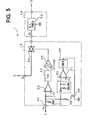
- a vehicle alternator control device 1 is provided to control the output voltage of an alternator 2 within a specified range.
- the alternator 2 comprises three-phase armature coils 21 in a stator (not shown), a field coil 22 in a rotor (not shown) and a full-wave rectifier circuit 23 for full-wave rectification of the three-phase outputs from armature coils 21.
- the alternator 2, particularly the rotor, is driven by an engine (not shown). Controlling the output voltage of the alternator 2 is accomplished by adjusting the field current to the field coil 22 by the alternator control device 1.
- An output terminal (terminal B) of the alternator 2 is connected to a vehicle battery 3 and other electrical loads (not shown) to supply electric current from the alternator 2.
- the vehicle alternator control device 1 includes a power transistor 11 connected in series with the field coil 22 as a first switching means for supplying and shutting off the field current; a flywheel diode 12 connected in parallel to the field coil 22 for flywheeling the field current when the power transistor 11 is turned off; a voltage control circuit 13 for monitoring the output voltage of the alternator 2 and controlling the on/off state of the power transistor 11 so that this output voltage is regulated within a specified range; a primary power supply circuit 14 for supplying electric power to maintain the operating state of the voltage control circuit 13; and a secondary power supply circuit 15 for detecting when the rotor of the alternator 2 turns, that is, when the engine rotates, based on an a.c. voltage of the y-phase (the y-phase voltage Py, for example) of the armature coil 21 to drive the primary power supply circuit 14.
- a power transistor 11 connected in series with the field coil 22 as a first switching means for supplying and shutting off the field current
- a flywheel diode 12 connected in
- the secondary power supply circuit 15 comprises voltage comparators 30 and 31, a counter circuit 32, an OR gate 33, an analog switch 34, a peak detector circuit 35, a timer circuit 36, resistors 37 and 38, and a transistor 39.
- the voltage comparator 30 generates a pulse signal according to the rotation speed of the alternator 2 by comparing and digitizing the y-phase voltage Py applied to an input terminal 40 with a specific reference voltage V1.
- the counter circuit 32 counts the pulse signals output from the voltage comparator 30. When the pulse count reaches a specific count N1, the output level inverts.
- the transistor 39 which is a MOSFET for example, is a second switching means for taking the leakage current in the armature coil 21 or full-wave rectifier circuit 23 to ground.
- the resistor 38 is connected between the input terminal 40 and transistor 39, and has a resistance lower than that of the resistor 37 connected between the input terminal 40 and ground.
- the peak detector circuit 35 detects the wave peak of the y-phase voltage Py applied to the input terminal 40, and includes a diode, a capacitor and a resistor.
- the voltage comparator 31 compares the peak of the y-phase voltage Py detected by the peak detector circuit 35 with a specific reference voltage V2 to determine if the peak value is greater than this specific the reference voltage V2. This reference voltage V2 is lower than the reference voltage V1 applied to the voltage comparator 30.
- the timer circuit 36 operates for a specific time period only when the y-phase voltage Py peak exceeds the reference voltage V2.
- the signal output from timer circuit 36 is input to the gate of the transistor 39, and controls the transistor 39 to turn on only while the timer circuit 36 is operating so that the leakage current flowing into the input terminal 40 is drained to ground.
- the analog switch 34 applies an operating voltage IG to the primary power supply circuit 14, and is on/off-controlled by the output of the OR gate 33.
- the output signal from the counter circuit 32 and a specific signal (described below) output from the primary power supply circuit 14 are input to the OR gate 33, which outputs the logical sum of these two input signals to the control terminal of the analog switch 34.
- the primary power supply circuit 14 has a voltage comparator 50, a counter circuit 51, and a direct current (d.c.) power supply circuit 52.
- the voltage comparator 50 outputs a pulse signal according to the rotation speed of the alternator 2 by comparing and digitizing the y-phase voltage Py with a specific reference voltage V3.
- This reference voltage V3 is set, for example, to the same voltage as the reference voltage V1 applied to the voltage comparator 30 in the secondary power supply circuit 15.
- the counter circuit 51 counts the pulses output from the voltage comparator 50, and the output logic inverts when the count reaches a specific count N2.
- This specific count N2 is set to a value less than the specific count N1 used by the counter circuit 32 in the secondary power supply circuit 15.
- the d.c. power supply circuit 52 generates the operating voltage of the voltage control circuit 13 and smoothes the terminal B voltage passed through the analog switch 34 in the secondary power supply circuit 15.
- the d.c. power supply circuit 52 also functions to remove a.c. ripple component and noise from the output voltage of the alternator 2 applied to the battery 3 from the terminal B when the alternator 2 is in power generating operation.
- the voltage control circuit 13 corresponds to the voltage control means, the primary power supply circuit 14 to the power supply means, and the secondary power supply circuit 15 to the power supply control means, respectively.
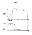
- the vehicle alternator control device 1 operates as shown in Fig. 3.
- the amplitude of the y-phase voltage Py applied to the input terminal 40 the of secondary power supply circuit 15 gradually increases.
- the voltage comparator 30 generates and outputs to the counter circuit 32 a specific pulse signal with the frequency proportional to the rotation speed of the alternator 2.
- the output level of the counter circuit 32 changes from low to high when the pulse count input to the counter 32 within a the specific period exceeds specific count N1, that is, when the speed of the alternator 2 reaches a frequency fs equivalent to this specific count N1, the analog switch 34 therefore turns on.
- the voltage applied from battery 3 through the terminal B of the alternator 2 is supplied to the d.c. power supply circuit 52 in the primary power supply circuit 14, and the voltage control circuit 13 starts controlling the output voltage of the alternator 2.
- the voltage appearing at the input terminal 40 will not exceed the reference voltage V1 applied to the voltage comparator 30, and the analog switch 34 remains in the off position. It should be noted that if the speed of the alternator 2 actually rises, the voltage at the input terminal 40 rises, and the transistor 39 turns on for the specific period. Thus, the voltage at the input terminal 40 will continue to rise and the analog switch 34 will turn on when the speed of the alternator 2 reaches the specific frequency fs.
- the d.c. power supply circuit 52 in the primary power supply circuit 14 starts operating.
- the d.c. power supply circuit 52 supplies the operating voltage to the voltage comparator 50 and counter circuit 51, to cause them to then start operating.
- the specific count N2 that is the reference for inverting the output of the counter circuit 51 is set to a value less than the specific count N1 set for the counter circuit 32 in the secondary power supply circuit 15, which operates to switch the analog switch 34 from off to on when the alternator starts turning, the counter circuit 51 output remains high and the analog switch 34 stays turned on as long as the rotation speed of the alternator 2 is above the low frequency fe equivalent to the specific count N2.
- the d.c. power supply circuit 52 in the primary power supply circuit 14 does not operate during the engine is being started, the counter 51 does not operate either yet.
- the primary power supply circuit 14 starts operating when the speed reaches the frequency fs equivalent to the specific count N1 set for the counter circuit 32 in the secondary power supply circuit 15.
- the output level of counter circuit 51 still stays high and the primary power supply circuit 14 continues operating.
- the primary power supply circuit 14 therefore continues operating even when the speed of the alternator 2 drops below the frequency fs equivalent to the specific count N1, and power supply to the battery 3 and other electrical loads is not interrupted.
- the power transistor 11 is controlled at this time by the voltage control circuit 13 to supply the field current to the field coil 22, induction voltage due to the magnetization is produced in the y-phase of the armature coil 22 and is easily digitized by the voltage comparator 30 to produce the pulse signal.
- the primary power supply circuit 14 therefore stops operating, field current supply to the field coil 22 stops, and power supply to the battery 3 and other electrical loads stops.
- the vehicle alternator control device 1 can thus prevent detection errors due to noise and improve detection accuracy because the high frequency fs is used for detection when the engine starts. More particularly, an increase in the circuit scale is not incurred because switching coils is not necessary, and the charge-discharge balance is not degraded because it is not necessary to increase the number of armature coil coils.
- the time constant of the field coil 22 of the alternator 2 is several hundred milliseconds, the time period from when slowing of the alternator 2 is detected to when the field current flow stops is generally longer than the time period from when the ignition switch is turned off to when the engine completely stops. It is therefore possible to control the power generating state of the alternator 2 without stopping the power supply from the alternator 2 during engine operation, and the signal wire needed to pass the ignition switch position to the vehicle alternator control device can be eliminated.
- the frequency fs for detecting engine starting is preferably set to less than approximately twice the threshold speed of the full excitation state of the alternator 2, and the frequency fe for detecting engine stopping is set to less than the threshold speed of the alternator 2.
- the threshold speed is set to correspond to a rotation speed where the alternator 2 starts its power generation.
- a vehicle alternator control device 1 according to the second embodiment shown in Fig. 4 differs from the vehicle alternator control device 1 shown in Fig. 1 in that an OR gate 16 is added between the power transistor 11 and the voltage control circuit 13. Further, the secondary power supply circuit 15 additionally has a pulse generator 41 on the output side of the timer circuit 36.
- the pulse generator 41 generates a pulse signal with a specific period when the timer circuit 36 operates and controls the transistor 39 to the on state. This pulse signal is input through the OR gate 16 to the gate of the power transistor 11. This pulse generator 41 corresponds to the field current supply means. Therefore, when the voltage of the input terminal 40 in the secondary power supply circuit 15 rises to the reference voltage V2, the pulse signal generated by the pulse generator 41 controls the power transistor 11 intermittently on, and the field current flows temporarily to the field coil 22. The voltage induced in the y-phase of the armature coil 21 can thus be amplified, and engine starting can be easily and reliably detected.
- a vehicle alternator control device 1 according to the third embodiment shown in Fig. 5 differs from the vehicle alternator control device 1 shown in Fig. 1 in that the secondary power supply circuit 15 has a frequency-to-voltage (F-V) converter 42 and a voltage comparator 43.
- F-V frequency-to-voltage
- the converter 42 converts the frequency of the input pulse signal to a voltage. Therefore, the output voltage of converter 42 rises as the speed of the alternator 2 increases, and conversely the output voltage of the converter 42 decreases as the speed of the alternator 2 decreases.
- the voltage comparator 43 has hysteresis and the output changes from low to high when the output voltage of converter 42 rises to a first reference voltage Vf1 or above. In addition, when the output voltage of converter 42 drops and reaches a second reference voltage Vf2 that is lower than the first reference voltage Vf1, the output of voltage comparator 43 changes from high to low.
- the reference voltages Vf1 and Vf2 may correspond to the frequencies fs and fe in Fig. 3.
- a relatively high speed is set for detecting engine starting.
- field current supply by the vehicle alternator control device 1 starts.
- a lower speed is set for detecting engine stopping.
- the vehicle alternator control device 1 stops supplying the field current.
Landscapes
- Engineering & Computer Science (AREA)
- Power Engineering (AREA)
- Control Of Eletrric Generators (AREA)
- Control Of Charge By Means Of Generators (AREA)
Claims (9)
- Fahrzeugwechselstromgenerator-Steuervorrichtung (1), welche umfasst:dadurch gekennzeichnet, dass das Energieversorgungs-Steuermittel dafür ausgelegt ist, den Betriebsspannungs-Erzeugungsbetrieb des Energieversorgungsmittels (14) zu unterbrechen, wenn die Phasenspannungsfrequenz unter eine zweite Bezugsfrequenz (fe) fällt, der unter der ersten Bezugsfrequenz (fs) liegt und unter einer vorgegebenen Frequenz, die der Leerlaufdrehzahl der Maschine entspricht.ein Spannungssteuermittel (13) zum Steuern der Ausgangsspannung eines von der Brennkraftmaschine angetriebenen Fahrzeugwechselstromgenerators (2) durch Ein- und Ausschalten einer ersten Schaltmittels (11), das mit einer Feldspule (22) des Wechselstromgenerators (2) in Reihe geschaltet ist; undein Energieversorgungsmittel (14) zum Zuführen der Betriebsspannung des Spannungssteuermittels (13); undein Energieversorgungs-Steuermittel (15) zum Starten eines Betriebsspannungs-Erzeugungsbetriebs des Energieversorgungsmittels (13), wenn die Frequenz einer Phasenspannung (Py) einer Ankerwicklung (21) des Wechselstromgenerators (2)eine erste Bezugsfrequenz (fs) übersteigt, die der Bedingung entspricht, dass die Maschine gestartet wird;
- Fahrzeugwechselstromgenerator-Steuervorrichtung (1) nach Anspruch 1, dadurch gekennzeichnet, dass:die erste Bezugsfrequenz (fs) weniger als das Doppelte der Schwellendrehzahl im Zustand vollständiger Erregung des Wechselstromgenerators beträgt; unddie zweite Bezugsfrequenz (fe) unter der Schwellendrehzahl liegt.
- Fahrzeugwechselstromgenerator-Steuervorrichtung (1) nach Anspruch 1 oder 2, ferner gekennzeichnet durch:ein zweites Schaltmittel (39), das zwischen einer Bezugspotentialseite einer Fahrzeugbatterie (3) und einem Pol (40) zum Erfassen der Phasenspannung (Py) vorgesehen ist; undein Schaltsteuermittel (31, 35, 36), um das zweite Schaltmittel (39) nur für einen bestimmten Zeitraum auf den EIN-Zustand zu steuern, wenn die Phasenspannung (Py) eine Bezugsspannung (V2) übersteigt.
- Fahrzeugwechselstromgenerator-Steuervorrichtung (1) nach Anspruch 3, gekennzeichnet durch:ein Feldstrom-Versorgungsmittel (41) zum Zuführen von Feldstrom zu der Feldspule (22), wenn das Schaltsteuermittel (31, 35, 36) das zweite Schaltmittel (39) auf den EIN-Zustand steuert.
- Fahrzeugwechselstromgenerator-Steuerverfahren für einen vom Verbrennungsmotor angetriebenen Wechselstromgenerator (2), der eine Ankerwicklung (21) und eine Feldspule (22) und ein Schaltmittel (11) zum Steuern der Feldstromzufuhr für die Feldspule (22) aufweist, um die Ausgangsspannung (Py) der Ankerwicklung (21) zu steuern, wobei das Verfahren die folgenden Schritte umfasst:Erfassen der Frequenz der Ausgangsspannung (Py) der Ankerwicklung (21);Starten der Feldstromzufuhr zur Feldspule (22), nachdem die erfasste Frequenz auf eine erste Bezugsfrequenz (fs) gestiegen ist, die der Bedingung entspricht, dass die Brennkraftmaschine gestartet wird; gekennzeichnet durch folgenden Schritt:Unterbrechen der Feldstromzufuhr zur Feldspule (22), nachdem die erfasste Frequenz unter eine zweite Bezugsfrequenz (fe) gefallen ist, die unter der ersten Bezugsfrequenz (fs) und unter einer vorgegebenen Frequenz liegt, die einer Leerlaufdrehzahl der Maschine entspricht.
- Fahrzeugwechselstromgenerator-Steuerverfahren nach Anspruch 5, ferner gekennzeichnet durch folgenden Schritt:Senken der Ausgangsspannung (Pv) der Ankerwicklung (21) für einen vorgegebenen Zeitraum nach Beginn der Drehung des Rotors.
- Fahrzeugwechselstromgenerator-Steuerverfahren nach Anspruch 6, ferner dadurch gekennzeichnet dass:im Frequenzerfassungsschritt die Ausgangsspannung (Py) der Ankerwicklung (21) mit einer ersten Bezugsspannung (V1) verglichen wird, um die Frequenz zu erfassen; undim Senkungsschritt der Spitzenwert der Ausgangsspannung (Py) der Ankerwicklung (21) mit einer zweiten Bezugsspannung (V2) verglichen wird, die niedriger ist als die erste Bezugsspannung (V1), um eine Spannungssenkungsoperation zu steuern.
- Fahrzeugwechselstromgenerator-Steuerverfahren nach Anspruch 6 oder 7, ferner gekennzeichnet durch den folgenden Schritt:Bewirken einer Feldstromzufuhr zur Feldspule (22) während eines vorgegebenen Zeitraums vor Beginn der Feldstromzufuhr zur Feldspule (22) im Startschritt.
- Fahrzeugwechselstromgenerator-Steuerverfahren nach einem der Ansprüche 5 bis 8, ferner dadurch gekennzeichnet, dass die erste Bezugsfrequenz (fs) höher ist als eine vorgegebene Frequenz, die einer Leerlaufdrehzahl der Brennkraftmaschine entspricht.
Applications Claiming Priority (2)
| Application Number | Priority Date | Filing Date | Title |
|---|---|---|---|
| JP2000336395 | 2000-11-02 | ||
| JP2000336395A JP4006941B2 (ja) | 2000-11-02 | 2000-11-02 | 車両用発電制御装置 |
Publications (3)
| Publication Number | Publication Date |
|---|---|
| EP1204200A2 EP1204200A2 (de) | 2002-05-08 |
| EP1204200A3 EP1204200A3 (de) | 2003-07-30 |
| EP1204200B1 true EP1204200B1 (de) | 2005-12-14 |
Family
ID=18811976
Family Applications (1)
| Application Number | Title | Priority Date | Filing Date |
|---|---|---|---|
| EP01125245A Expired - Lifetime EP1204200B1 (de) | 2000-11-02 | 2001-10-24 | Fahrzeugsalternatorsteuerungsvorrichtung und -verfahren |
Country Status (4)
| Country | Link |
|---|---|
| US (1) | US6603289B2 (de) |
| EP (1) | EP1204200B1 (de) |
| JP (1) | JP4006941B2 (de) |
| DE (1) | DE60115815T2 (de) |
Cited By (1)
| Publication number | Priority date | Publication date | Assignee | Title |
|---|---|---|---|---|
| WO2013050625A1 (en) | 2011-10-06 | 2013-04-11 | Grindeks, A Joint Stock Company | Antiviral efficacy of disodium 2,6-dimethyl-1,4-dihydropyridine-3,5-bis(carbonyloxyacetate) and its derivatives |
Families Citing this family (8)
| Publication number | Priority date | Publication date | Assignee | Title |
|---|---|---|---|---|
| JP4006941B2 (ja) * | 2000-11-02 | 2007-11-14 | 株式会社デンソー | 車両用発電制御装置 |
| JP3982247B2 (ja) * | 2001-12-06 | 2007-09-26 | 株式会社デンソー | 車両用発電機の制御装置 |
| CN100358234C (zh) * | 2002-07-31 | 2007-12-26 | E.On瑞典股份公司 | 电机 |
| US7605569B2 (en) | 2007-01-31 | 2009-10-20 | Infineon Technologies Ag | Acquisition circuit and controller circuit for an alternator |
| JP5445185B2 (ja) * | 2010-02-05 | 2014-03-19 | 株式会社デンソー | 車両用発電機 |
| JP5201196B2 (ja) | 2010-11-12 | 2013-06-05 | 株式会社デンソー | 車両用発電制御装置 |
| JP6477600B2 (ja) | 2016-05-30 | 2019-03-06 | 株式会社デンソー | 再始動制御システム |
| TWI620408B (zh) * | 2016-12-21 | 2018-04-01 | 朋程科技股份有限公司 | 調節器、車用交流發電機及其轉速偵測方法 |
Family Cites Families (14)
| Publication number | Priority date | Publication date | Assignee | Title |
|---|---|---|---|---|
| US4384245A (en) * | 1980-08-12 | 1983-05-17 | Trw Inc. | Alternator voltage regulator |
| JPS6244698U (de) | 1985-09-09 | 1987-03-18 | ||
| JP2576233B2 (ja) * | 1989-07-13 | 1997-01-29 | 三菱電機株式会社 | 車両用交流発電機の制御装置 |
| US5266836A (en) * | 1992-06-30 | 1993-11-30 | Ford Motor Company | Method and apparatus for operating a motor vehicle alternator |
| JPH06335298A (ja) * | 1993-03-23 | 1994-12-02 | Mitsubishi Electric Corp | 車両用交流発電機の出力制御方法及び出力制御装置 |
| JPH06284598A (ja) * | 1993-03-29 | 1994-10-07 | Sawafuji Electric Co Ltd | 車両用充電発電装置 |
| JPH06292329A (ja) | 1993-04-05 | 1994-10-18 | Mitsubishi Electric Corp | 車両用交流発電機の出力制御装置 |
| US5429687A (en) | 1994-01-03 | 1995-07-04 | Ateliers Thome-Genot | Process for manufacturing alternator pole piece |
| JP3897832B2 (ja) * | 1995-06-23 | 2007-03-28 | 株式会社デンソー | 車両用電源装置 |
| US6215285B1 (en) * | 1999-10-20 | 2001-04-10 | Delphi Technologies, Inc. | Apparatus and method for providing an output signal indicative of engine rotational speed and/or generator rotational speed |
| JP3509007B2 (ja) * | 2000-06-29 | 2004-03-22 | 株式会社デンソー | 車両用交流発電機 |
| JP3519048B2 (ja) * | 2000-10-18 | 2004-04-12 | 三菱電機株式会社 | 車両用交流発電機の電圧制御装置 |
| JP4006941B2 (ja) * | 2000-11-02 | 2007-11-14 | 株式会社デンソー | 車両用発電制御装置 |
| US6483198B2 (en) * | 2001-01-19 | 2002-11-19 | Transportation Techniques Llc | Hybrid electric vehicle having a selective zero emission mode, and method of selectively operating the zero emission mode |
-
2000
- 2000-11-02 JP JP2000336395A patent/JP4006941B2/ja not_active Expired - Fee Related
-
2001
- 2001-10-18 US US09/978,537 patent/US6603289B2/en not_active Expired - Fee Related
- 2001-10-24 DE DE60115815T patent/DE60115815T2/de not_active Expired - Lifetime
- 2001-10-24 EP EP01125245A patent/EP1204200B1/de not_active Expired - Lifetime
Cited By (1)
| Publication number | Priority date | Publication date | Assignee | Title |
|---|---|---|---|---|
| WO2013050625A1 (en) | 2011-10-06 | 2013-04-11 | Grindeks, A Joint Stock Company | Antiviral efficacy of disodium 2,6-dimethyl-1,4-dihydropyridine-3,5-bis(carbonyloxyacetate) and its derivatives |
Also Published As
| Publication number | Publication date |
|---|---|
| US6603289B2 (en) | 2003-08-05 |
| DE60115815T2 (de) | 2006-09-14 |
| US20020050810A1 (en) | 2002-05-02 |
| EP1204200A2 (de) | 2002-05-08 |
| EP1204200A3 (de) | 2003-07-30 |
| JP2002142497A (ja) | 2002-05-17 |
| DE60115815D1 (de) | 2006-01-19 |
| JP4006941B2 (ja) | 2007-11-14 |
Similar Documents
| Publication | Publication Date | Title |
|---|---|---|
| US5144220A (en) | Vehicle ac generator control system | |
| JPH08298731A (ja) | 車両用発電装置 | |
| JPH08126223A (ja) | 交流発電機の制御装置 | |
| US4477766A (en) | Apparatus for controlling electric generation for vehicles | |
| US6566845B2 (en) | Automotive alternator having detector for detecting initiation of rotation | |
| US6433519B2 (en) | Voltage control unit for vehicular AC generator | |
| US6215284B1 (en) | Control device of A.C. generator for vehicle | |
| US4727307A (en) | Control apparatus for vehicular generator | |
| US6664767B2 (en) | Voltage regulator of vehicle AC generator having variable bypass circuit resistance | |
| EP1204200B1 (de) | Fahrzeugsalternatorsteuerungsvorrichtung und -verfahren | |
| US7365520B2 (en) | Vehicle-generator output voltage control apparatus | |
| US6614207B2 (en) | Vehicular power generator control apparatus having maximum conduction rate limiting function | |
| KR0123543B1 (ko) | 차량용 교류발전기의 전압조정기 | |
| US4222005A (en) | Testing device for generator output voltage regulators | |
| US6741067B2 (en) | Power generation controller and method for a vehicle | |
| JPH06197473A (ja) | 車両用充電発電機の制御装置 | |
| JPH0421440B2 (de) | ||
| KR100270788B1 (ko) | 차량용 발전기의 제어장치 | |
| JPH0528905Y2 (de) | ||
| JPH0746898A (ja) | 車両用充電発電機 | |
| JPH063976B2 (ja) | オルタネ−タ制御装置 | |
| JP2002345298A (ja) | 車両用発電機の制御装置 | |
| JP4006614B2 (ja) | 車両用交流発電機 | |
| JPS60121999A (ja) | エンジン駆動自励式発電機 | |
| JPS6336220B2 (de) |
Legal Events
| Date | Code | Title | Description |
|---|---|---|---|
| PUAI | Public reference made under article 153(3) epc to a published international application that has entered the european phase |
Free format text: ORIGINAL CODE: 0009012 |
|
| AK | Designated contracting states |
Kind code of ref document: A2 Designated state(s): AT BE CH CY DE DK ES FI FR GB GR IE IT LI LU MC NL PT SE TR |
|
| AX | Request for extension of the european patent |
Free format text: AL;LT;LV;MK;RO;SI |
|
| PUAL | Search report despatched |
Free format text: ORIGINAL CODE: 0009013 |
|
| AK | Designated contracting states |
Designated state(s): AT BE CH CY DE DK ES FI FR GB GR IE IT LI LU MC NL PT SE TR |
|
| AX | Request for extension of the european patent |
Extension state: AL LT LV MK RO SI |
|
| RIC1 | Information provided on ipc code assigned before grant |
Ipc: 7H 02P 9/30 A Ipc: 7H 02J 7/14 B Ipc: 7H 02J 7/24 B |
|
| 17P | Request for examination filed |
Effective date: 20030905 |
|
| AKX | Designation fees paid |
Designated state(s): DE FR IT |
|
| GRAP | Despatch of communication of intention to grant a patent |
Free format text: ORIGINAL CODE: EPIDOSNIGR1 |
|
| GRAS | Grant fee paid |
Free format text: ORIGINAL CODE: EPIDOSNIGR3 |
|
| GRAA | (expected) grant |
Free format text: ORIGINAL CODE: 0009210 |
|
| AK | Designated contracting states |
Kind code of ref document: B1 Designated state(s): DE FR IT |
|
| PG25 | Lapsed in a contracting state [announced via postgrant information from national office to epo] |
Ref country code: IT Free format text: LAPSE BECAUSE OF FAILURE TO SUBMIT A TRANSLATION OF THE DESCRIPTION OR TO PAY THE FEE WITHIN THE PRESCRIBED TIME-LIMIT;WARNING: LAPSES OF ITALIAN PATENTS WITH EFFECTIVE DATE BEFORE 2007 MAY HAVE OCCURRED AT ANY TIME BEFORE 2007. THE CORRECT EFFECTIVE DATE MAY BE DIFFERENT FROM THE ONE RECORDED. Effective date: 20051214 |
|
| REF | Corresponds to: |
Ref document number: 60115815 Country of ref document: DE Date of ref document: 20060119 Kind code of ref document: P |
|
| ET | Fr: translation filed | ||
| PLBE | No opposition filed within time limit |
Free format text: ORIGINAL CODE: 0009261 |
|
| STAA | Information on the status of an ep patent application or granted ep patent |
Free format text: STATUS: NO OPPOSITION FILED WITHIN TIME LIMIT |
|
| 26N | No opposition filed |
Effective date: 20060915 |
|
| PGFP | Annual fee paid to national office [announced via postgrant information from national office to epo] |
Ref country code: FR Payment date: 20121018 Year of fee payment: 12 |
|
| PGFP | Annual fee paid to national office [announced via postgrant information from national office to epo] |
Ref country code: IT Payment date: 20121013 Year of fee payment: 12 |
|
| PGFP | Annual fee paid to national office [announced via postgrant information from national office to epo] |
Ref country code: DE Payment date: 20131021 Year of fee payment: 13 |
|
| REG | Reference to a national code |
Ref country code: FR Ref legal event code: ST Effective date: 20140630 |
|
| PG25 | Lapsed in a contracting state [announced via postgrant information from national office to epo] |
Ref country code: FR Free format text: LAPSE BECAUSE OF NON-PAYMENT OF DUE FEES Effective date: 20131031 Ref country code: IT Free format text: LAPSE BECAUSE OF NON-PAYMENT OF DUE FEES Effective date: 20131024 |
|
| REG | Reference to a national code |
Ref country code: DE Ref legal event code: R119 Ref document number: 60115815 Country of ref document: DE |
|
| PG25 | Lapsed in a contracting state [announced via postgrant information from national office to epo] |
Ref country code: DE Free format text: LAPSE BECAUSE OF NON-PAYMENT OF DUE FEES Effective date: 20150501 |