EP1204197A2 - Einrichtung und Verfahren zur netzseitigen Regelung der Zwischenkreisspannung - Google Patents
Einrichtung und Verfahren zur netzseitigen Regelung der Zwischenkreisspannung Download PDFInfo
- Publication number
- EP1204197A2 EP1204197A2 EP01124103A EP01124103A EP1204197A2 EP 1204197 A2 EP1204197 A2 EP 1204197A2 EP 01124103 A EP01124103 A EP 01124103A EP 01124103 A EP01124103 A EP 01124103A EP 1204197 A2 EP1204197 A2 EP 1204197A2
- Authority
- EP
- European Patent Office
- Prior art keywords
- voltage
- harmonics
- intermediate circuit
- mains
- network
- Prior art date
- Legal status (The legal status is an assumption and is not a legal conclusion. Google has not performed a legal analysis and makes no representation as to the accuracy of the status listed.)
- Granted
Links
- 238000000034 method Methods 0.000 title claims abstract description 37
- 230000033228 biological regulation Effects 0.000 title claims description 17
- 230000001105 regulatory effect Effects 0.000 claims abstract description 26
- 230000009466 transformation Effects 0.000 claims abstract description 19
- 230000001131 transforming effect Effects 0.000 claims abstract 5
- 230000010355 oscillation Effects 0.000 claims description 21
- 238000001914 filtration Methods 0.000 claims description 16
- 238000005070 sampling Methods 0.000 claims description 16
- 238000004364 calculation method Methods 0.000 claims description 13
- 230000008569 process Effects 0.000 claims description 4
- 230000002441 reversible effect Effects 0.000 claims description 2
- 238000010586 diagram Methods 0.000 description 19
- 230000006870 function Effects 0.000 description 10
- 230000001360 synchronised effect Effects 0.000 description 7
- 230000008901 benefit Effects 0.000 description 6
- 238000012546 transfer Methods 0.000 description 6
- 230000000694 effects Effects 0.000 description 5
- 238000012935 Averaging Methods 0.000 description 4
- 230000003137 locomotive effect Effects 0.000 description 4
- 230000010354 integration Effects 0.000 description 3
- 230000000737 periodic effect Effects 0.000 description 3
- 238000012545 processing Methods 0.000 description 3
- 238000001228 spectrum Methods 0.000 description 3
- 230000004913 activation Effects 0.000 description 2
- 230000006399 behavior Effects 0.000 description 2
- 238000013461 design Methods 0.000 description 2
- 238000011161 development Methods 0.000 description 2
- 230000018109 developmental process Effects 0.000 description 2
- 230000006872 improvement Effects 0.000 description 2
- 230000010363 phase shift Effects 0.000 description 2
- 238000003775 Density Functional Theory Methods 0.000 description 1
- 238000013459 approach Methods 0.000 description 1
- 230000005540 biological transmission Effects 0.000 description 1
- 230000015572 biosynthetic process Effects 0.000 description 1
- 239000003990 capacitor Substances 0.000 description 1
- 238000006243 chemical reaction Methods 0.000 description 1
- 238000005352 clarification Methods 0.000 description 1
- 230000001276 controlling effect Effects 0.000 description 1
- 230000007423 decrease Effects 0.000 description 1
- 238000001514 detection method Methods 0.000 description 1
- 230000001771 impaired effect Effects 0.000 description 1
- 230000001939 inductive effect Effects 0.000 description 1
- 238000012905 input function Methods 0.000 description 1
- 238000007689 inspection Methods 0.000 description 1
- 238000005259 measurement Methods 0.000 description 1
- 230000001172 regenerating effect Effects 0.000 description 1
- 238000000844 transformation Methods 0.000 description 1
Images


Classifications
-
- B—PERFORMING OPERATIONS; TRANSPORTING
- B60—VEHICLES IN GENERAL
- B60L—PROPULSION OF ELECTRICALLY-PROPELLED VEHICLES; SUPPLYING ELECTRIC POWER FOR AUXILIARY EQUIPMENT OF ELECTRICALLY-PROPELLED VEHICLES; ELECTRODYNAMIC BRAKE SYSTEMS FOR VEHICLES IN GENERAL; MAGNETIC SUSPENSION OR LEVITATION FOR VEHICLES; MONITORING OPERATING VARIABLES OF ELECTRICALLY-PROPELLED VEHICLES; ELECTRIC SAFETY DEVICES FOR ELECTRICALLY-PROPELLED VEHICLES
- B60L9/00—Electric propulsion with power supply external to the vehicle
- B60L9/16—Electric propulsion with power supply external to the vehicle using AC induction motors
-
- H—ELECTRICITY
- H02—GENERATION; CONVERSION OR DISTRIBUTION OF ELECTRIC POWER
- H02M—APPARATUS FOR CONVERSION BETWEEN AC AND AC, BETWEEN AC AND DC, OR BETWEEN DC AND DC, AND FOR USE WITH MAINS OR SIMILAR POWER SUPPLY SYSTEMS; CONVERSION OF DC OR AC INPUT POWER INTO SURGE OUTPUT POWER; CONTROL OR REGULATION THEREOF
- H02M1/00—Details of apparatus for conversion
- H02M1/12—Arrangements for reducing harmonics from AC input or output
-
- B—PERFORMING OPERATIONS; TRANSPORTING
- B60—VEHICLES IN GENERAL
- B60L—PROPULSION OF ELECTRICALLY-PROPELLED VEHICLES; SUPPLYING ELECTRIC POWER FOR AUXILIARY EQUIPMENT OF ELECTRICALLY-PROPELLED VEHICLES; ELECTRODYNAMIC BRAKE SYSTEMS FOR VEHICLES IN GENERAL; MAGNETIC SUSPENSION OR LEVITATION FOR VEHICLES; MONITORING OPERATING VARIABLES OF ELECTRICALLY-PROPELLED VEHICLES; ELECTRIC SAFETY DEVICES FOR ELECTRICALLY-PROPELLED VEHICLES
- B60L2200/00—Type of vehicles
- B60L2200/26—Rail vehicles
Definitions
- the present invention relates to an apparatus and a method for the network-side regulation of voltages, especially of intermediate circuit voltages.
- the second harmonic in the DC link power generates only a very low due to a low impedance in this frequency range small second harmonic in the DC link voltage. Therefore, in the case of one Mains voltage without harmonics the DC link voltage fluctuation negligibly small due to the second harmonic.
- harmonics continue to occur in the intermediate circuit Mains voltage harmonics must be tolerated, however, by the device according to the invention and the method according to the invention Network interference significantly reduced compared to the prior art and it becomes a stable network-side regulation of an intermediate circuit voltage possible.
- An intermediate circuit is conventionally connected between the network and a motor.
- a device for regulating an intermediate circuit voltage on the network side adjusts a power drawn from the network to that required by the motor Performance.
- a difference between purchased and delivered power changes the DC link voltage value.
- the mains current should normally be in phase be regulated to the mains voltage or when regenerating in the opposite phase. Only in exceptional cases is there a phase shift between the mains current and mains voltage required.
- the power drawn on the network side must be delivered to the motor side Performance can be adjusted.
- a difference between the output and related power changes the intermediate circuit voltage because of an intermediate circuit capacitor being charged or discharged.
- a facility for the network side Regulation of the intermediate circuit voltage therefore automatically adjusts the line side related power to the power output on the motor side.
- the DC link draws power from the motor, which is fed back into the network.
- the device according to the invention for regulating the sinusoidal variables uses a pointer control.
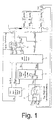
- a simplified one The control scheme according to the invention for these sinusoidal variables is shown in FIG. 1 shown.
- an intermediate circuit voltage regulator 1 generates a target current I ZK-n .
- This target current I ZK-n yields when multiplied by an intermediate circuit voltage U ZK or a target value of the intermediate circuit voltage U ZK-n is a nominal power P ZK-n which is to be obtained from the network side.
- This target power is fed to a calculation device 2.
- the grid current setpoint pointer I Ns and the inverter setpoint voltage pointer U WRi are then transformed into the time domain in a transformation device 3 using the inverse Fourier transform or IFT, resulting in a grid current setpoint i Ns (t) and an inverter setpoint voltage u WRi-s (t) , Furthermore, a mains current control device 4 is implemented in the time domain and has the task of leading a mains current i N (t) to its sinusoidal mains current setpoint i Ns (t). The grid current control device 4 corrects the nominal inverter voltage u WRi-s (t) in the event of parameter changes, for example in the event of a temperature dependence of the grid choke.
- mains current control device 4 By implementing the mains current control device 4 in the time domain, direct current or DC components in the mains current are avoided, provided that they are not already present in the mains current setpoint i Ns (t). Mains voltage harmonics are also applied to the inverter set voltage u WRi-s (t).
- dynamic filter device for intermediate circuit voltages device for Setpoint specification of the DC link voltage when starting the system or Idling problems
- device for dead time compensation of mains voltage harmonics which, however, are described separately below their functions are explained.
- the intermediate circuit voltage regulator 1 is used to calculate the required target power P ZK-n from the generated intermediate circuit target current I ZK-n and the intermediate circuit voltage U ZK . From this target power P ZK-n , a mains current setpoint pointer I Ns is calculated in the computing device together with the mains voltage pointer U N.
- the line current i N should normally be in phase or in phase opposition to the line voltage.
- I N-qsoll a capacitive or inductive current component is required in an exceptional situation , this is specified via I N-qsoll by a higher-level control device, which will not be discussed further here.
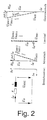
- inverter setpoint voltage pointer U WRi a grid current pointer I N is formed by the calculation device , as shown in FIG. 2.
- the phase current and amplitude of the network current pointer I N can be regulated via the pointer relationship between the network voltage pointer U N and the inverter sum voltage pointer U WR ⁇ .
- the control in the control system 5 is based on a pointer control.
- the controlled system device 5 therefore carries out a transformation of network-frequency variables and maps them as DC or DC variables in the network-frequency coordinate system.
- This has the advantage that the regulation of DC variables is particularly simple.
- the discrete Fourier transform (DFT) is preferably used in the control system device 5 to transform the measured variables, for example the line voltage u N (t).
- a transformation with e -j ⁇ GS t into a network-frequency coordinate system could also be carried out, in which all time variables, including harmonics, are transformed into the same coordinate system, fundamental vibrations are mapped as DC variables and harmonics continue to occur, but with a different frequency.
- this transformation process is not described here.
- the control reacts accordingly "restlessly" to the harmonics.
- the DFT is here preferred transformation process.
- a well-known at DFT Method for influencing DC link fluctuations the harmonics set in the mains current.
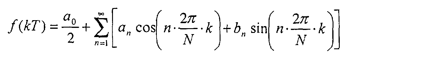
- the input functions are ideally scanned synchronously with the network frequency.
- the integration over a period becomes a summation over N sampling points.
- N is the number of samples per fundamental period.
- the controlled system device 5 Since the DFT carries out a summation over a period, the controlled system device 5 does not immediately jump to the entrance react. It requires a period to reach the stationary end value to reach.
- the fundamental oscillation network voltage pointer U N-GS , the network voltage setpoint pointer I Ns and the inverter target voltage pointer U WRi are transformed back from the frequency domain into the time domain with the aid of the inverse Fourier transformation or IFT.
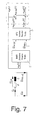
- the controlled system device 5 which is shown in FIG. 3 in the form of a block diagram, includes, among other things, a "phase locked loop" control loop or PLL control loop 5a.
- the grid-side inverter is synchronized with the grid frequency so that it can generate a sinusoidal current that is synchronous with the grid frequency.
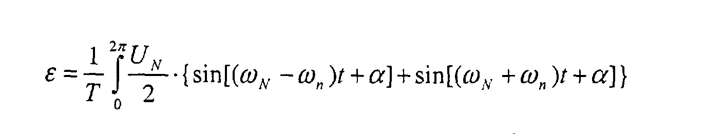
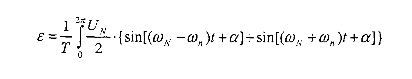
- the sinusoidal mains voltage of the frequency ⁇ N is multiplied by the cosine of the PLL frequency ⁇ n to be tracked, taking into account the phase position.
- the PLL control circuit 5a must therefore be limited to a specific frequency range so that it only "snaps" onto the fundamental vibration.
- the PLL control loop 5a and the DFT 5b of the fundamental wave are shown in FIG. 3.
- the PLL control loop 5a is a closed control loop, which is an averager X instead of integration.
- phase jump in the mains voltage a time delay and a settling of the output variable occur.
- a phase jump in the line voltage can be generated, for example, by shedding a load of a second locomotive on the same line section with a partly common line impedance. The effect would be a mains current that is not in phase with the mains voltage during this time, which is classified as uncritical here.
- a jump in amplitude in the mains voltage can also be caused by a load shedding of a second locomotive.
- the DC link voltage regulator 1 will now be discussed in more detail below.
- the intermediate circuit voltage regulator 1 pre-controls a load current I ZK-m or I L from the intermediate circuit.
- the load current I L which is taken from the intermediate circuit on the motor side, is fed to the intermediate circuit voltage regulator 1 and is added directly, almost instantaneously, to the desired value I C of an intermediate circuit voltage regulating unit 1a by an addition device 1b.
- the network-side control already requires a power P ZK before the intermediate circuit voltage U ZK has dropped.
- the load current I L can be determined in various ways, but these are not shown, for example by calculation by the motor control or by indirect measurement, for example, of the pulsed intermediate circuit current, very good filtering with a correspondingly large dead time being required.
- the device according to the invention is designed such that a DC share in the grid current is avoided, which is necessary for the transformers do not saturate in the substations.
- the mains current control device 4 is realized in the time domain. Due to the realization in the time domain, the Mains current control device 4 in principle capable of a DC component in the mains currentenfinregeln. Even very small DC currents are or I component recorded and corrected. All you have to do is ensure that the current detection and the analog-digital or AD conversion are accurate are enough.
- the DC component i N-DC in the mains current setpoint i Ns can be compensated for by suitable filtering.
- the mains current control device 4 according to the invention with regulation of the DC component i N-DC in the mains current setpoint i Ns is shown in FIG. 6 in the form of a block diagram.
- the mains current control device 4 comprises a flowing mean value filter 4a and a PI control device 4b connected downstream of it.
- the DC component i N-DC in the mains current setpoint i Ns is determined by the mains current control device 4 via the flowing mean value filter 4a.
- the flowing mean value filter 4a sums up all the time-discrete values of the mains current setpoint i Ns over one (or more) periods. If there are otherwise only line frequency components in the line current setpoint i Ns , the exact DC component i N-DC of the line current setpoint i Ns is determined after just one period.
- a device for supply voltage 6 is also formed, the block diagram of which is shown in FIG. 7.
- This device for supply voltage 6 has the task of relieving the supply current control device 4 at supply voltage harmonics.
- a compensation determination device 7a is designed for precalculating the grid voltage u NV (t) to be controlled.
- the control concept implemented by this device for supplying mains voltage 6 is based on pointer control of the fundamental oscillation quantities.
- the goal is a sinusoidal current without harmonics. This is true if the voltage drop U LN across the line choke contains only a fundamental component.
- the harmonics in the grid voltage U N-OS and in the short-term mean value of the inverter total voltage U WR-n ⁇ -OS must be the same. This will be achieved by applying the mains voltage harmonics to the total inverter voltage.
- the processing time can be just before scanning and processing Transfer of the next degree of modulation to the PWM can be reduced.
- the dead time of the PWM cannot be reduced with a scan control.
- the error voltage amplitude at 83 ms dead time is at 15kV / 16.7 Hz network shown in Fig. 8.
- the large error cannot be accepted with this dead time.
- the error is greater than the mains voltage harmonic • ⁇ U N-nOS •, which should also be compensated, at least partially, at this frequency.
- the first option with DFT / IFT is conventional with high transformer leakage inductance used. Here only the fundamental, the third and fifth Harmonic considered.
- FIGS Dead time compensation a block diagram of an inventive Mains voltage connection with dead time explained in more detail.
- the dead time compensation by the device for dead time compensation 7 is intended to perform the task of estimating a future mains voltage value u NV (t).
- the device for dead time compensation 7 adds a small estimated value ⁇ u comp (t) to the instantaneous value of the mains voltage u N (t), which is obtained from experience with the last periods.
- the estimated value ⁇ u comp (t) is periodic in the case of stationary signals and can therefore be obtained from the voltages u N ((kN) T) of the last period by the compensation determination device 7a. 9 is T the sampling time, N the number of samples per network period and k indicates the respective sampled instantaneous value.
- a filter device 8 can be formed after this by the compensation determination device 7a, which alone is sufficient for the dead time compensation.
- 8 values are stored in the filter device over several network periods and a flowing averaging is carried out over several periods.
- the filtered estimated value ⁇ u comp (t) is then added to the instantaneous value of the mains voltage u N (t). Subsequently, the resulting supply voltage u NV (t) to be controlled is fed to the device for supply voltage connection 6 which has a dead time.
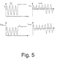
- the mains voltage u N contains strong harmonics in this example.
- the voltage ⁇ u comp is shown, which results from the differential voltage of the mains voltage of two successive sampling times and is determined by the compensation determination device 7a.
- the voltage ⁇ u comp is also periodic.
- the voltage ⁇ u k-fil contains the averaging over 4 values, one for each period, which are identified in FIG. 11 by o and *.
- the line voltage u NV to be controlled results from the addition of the current line voltage u N and the voltage ⁇ u k-fil , which is formed by the compensation determination device 7a and the filter device 8 from the line voltage of the last periods.
- the compensation determination device 7a shown in FIG. 10 The calculation performed is illustrated below using some examples.
- a 16.7 Hz network was assumed.
- the filtering is carried out over 4 periods.
- the effectiveness of the activation decreases with frequency due to the asynchronous sampling.
- the error due to the scanning is very small on the one hand, and on the other hand, cause-related harmonic harmonics, for example from vehicles with phase synchronous phase control, are to be expected.
- the dead time compensation places high demands the accuracy of the sampling or the synchronization of the PLL control loop:
- the accuracy should be at e.g. 1 Hz, this corresponds to an accuracy of 1 Hz / 33 during synchronization to the 16.7 Hz fundamental (corresponding to 0.18%).
- the dead time compensation only up to the lower kHz range brings advantages.
- the device for supply voltage 6 with device for dead time compensation 7 should therefore have a low-pass filter device (not shown) be designed at the input, which the high frequencies from a few kHz filters out.
- the exact design of the maximum usable frequency can only be started a specific application.
- the dead time compensation found a good and dynamic solution. Down to the lower kHz range an increase in input impedance is expected.
- the transmission of harmonics from the intermediate circuit voltage U ZK to the mains current setpoint I Ns can be shown very clearly on the corresponding control path.
- the DC link voltage regulator 1 with PI control converts a harmonic in the DC link voltage U ZK into a phase-shifted harmonic of the same frequency in the power request P ZK-s or in the mains current setpoint pointer I Ns .
- the IFT, ie the transformation into the time domain there are harmonics in the mains current setpoint i Ns (t).
- a fourth harmonic in the intermediate circuit voltage U ZK generates a phase-shifted fourth harmonic in the power requirement P ZK-ns (t).
- the mains current setpoint of the mains current setpoint pointer I Ns is proportional to the power requirement P ZK-ns and therefore also contains a fourth harmonic.
- P ZK-ns ( t ) P ZK-DC + P ZK -4 Sin (4 ⁇ t + ⁇ )
- I ns I N - DC + I N -4 Sin (4 ⁇ t + ⁇ )
- i ns ( t ) ⁇ I N - DC + I N -4 Sin (4 ⁇ t + ⁇ ) ⁇ ⁇ sin ( ⁇ t )
- i ns ( t ) I N - DC Sin ( ⁇ t ) + I N -4 2 * Sin (3 ⁇ t ) + I N -4 2 * Sin (5 ⁇ t )
- a second harmonic in the intermediate circuit voltage U ZK generates a phase-shifted second harmonic in the power requirement P ZK-ms (t). Together with the basic oscillation requirement of the mains current, this results in a first and third harmonic in the nominal value of the mains current.
- the harmonics must be filtered out so that harmonics in the intermediate circuit voltage U ZK are not transferred to the mains current I N. This should not be achieved with a low-pass filter, as dynamic DC link voltage changes due to load jumps should be compensated for without dead time if possible.
- a dynamic filter device 9 is therefore formed, in which the harmonics are filtered and then subtracted from the actual value of the intermediate circuit voltage U ZK .
- the second, fourth, sixth, etc. harmonics are to be filtered from the intermediate circuit voltage U ZK , special emphasis being placed on filtering the fourth harmonic, since this significantly influences the intermediate circuit power due to its dominance in the voltage.
- the dynamic filter device 9 according to a first exemplary embodiment of the invention is constructed as shown in FIG. 17A and implemented in a sampling control device (not shown).
- the intermediate circuit voltage U ZK (t) here an intermediate circuit voltage in which only 2n-fold harmonics are taken into account, is fed to a DFT transformation device 10a.
- the 2nd to 2nth harmonics of the intermediate circuit voltage U 2n-ist are thus filtered out from the resulting intermediate circuit voltage U 2n-fil .
- 17B shows harmonics from past network periods be calculated.
- This second method according to the invention and its The structure in the block diagram is analyzed in more detail below.
- a dynamic filter device 9 as shown in FIG. 17B, is implemented in the scan control device (not shown).
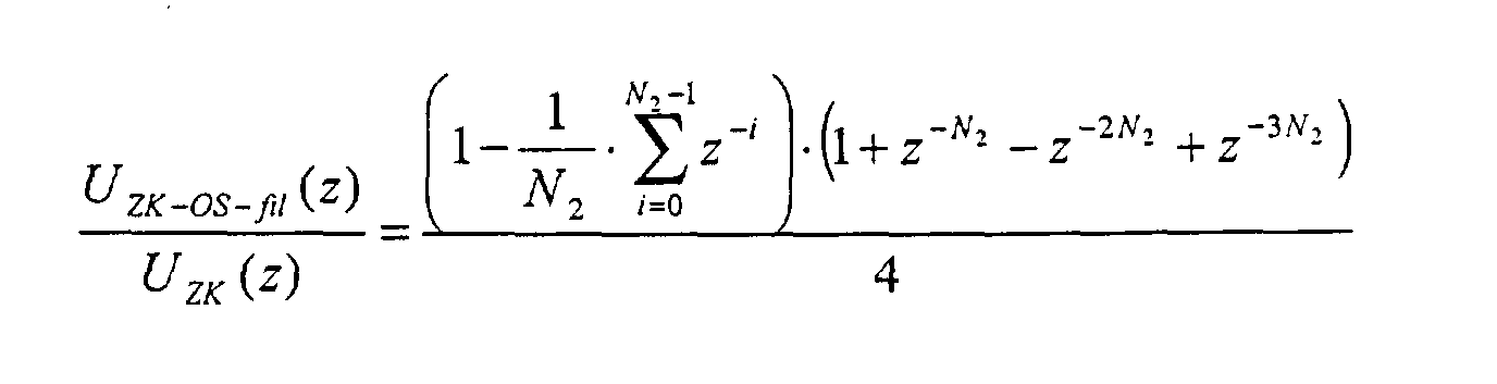
- a flowing averaging U ZK-mi (t) is carried out over half a network period, corresponding to N 2 samples, by an averager 11a. From the second harmonic, all straight harmonics are thus filtered out, as shown in the signal profiles according to FIGS. 18 and 19. This results from the fact that the integral becomes zero over a half-period at a double or 2n-fold harmonic.
- the harmonics U ZK-OS (t) are obtained by subtracting the flowing mean U ZK-mi (t) determined by the averager 11a from the actual value U ZK (t).
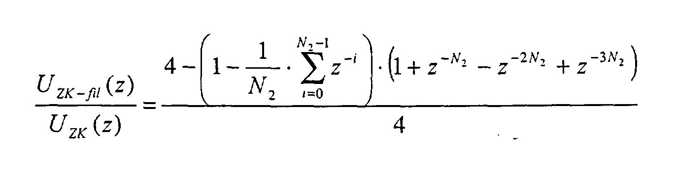
- the harmonics U ZK-OS (t) are then filtered in a filter device 11b, which is similar to a so-called comb filter. With this filter device 11b, however, it should be noted that the 2n-fold harmonics are not impaired. For this reason, a flowing mean value filter device is proposed, which has a separate mean value filter for each value of a half period. The filter device 11b forms the flowing mean value over N fil values, one value per half network period and at the corresponding point of the other half periods.
- U ZK-OS ( kT ) U ZK ( kT ) - U ZK - Wed. ( kT )
- U ZK-fil ( kT ) U ZK ( kT ) - U ZK-OS-fil ( kT )
- This device according to the invention and the method according to the invention bring for all relevant harmonics, especially the fourth harmonic and the lower, second, sixth and eighth harmonics good results.
- U N-3OS 20%
- U N-GS U N-9OS 5.0%
- U N-GS U N-5OS 8.5%
- U N-GS U N-11OS 4.5%
- U N-GS U N-7OS 7.5%
- the intermediate circuit voltage U ZK contains strong harmonics in both cases. Without the device according to the invention for regulating an intermediate circuit voltage on the network side (left-hand illustration in FIG. 20), these go directly into the power requirement P ZK of the intermediate circuit voltage regulating device and are transferred to the nominal value of the mains current.
- the mains current i N (t) contains very high harmonics.
- the distorted intermediate circuit voltage U ZK (right in FIG. 20) is filtered very well in U ZK-fil .
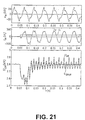
- the filter algorithm only filters out the harmonics with even multiples of the mains frequency and therefore hardly any dynamics are lost in the event of load jumps, as can be seen from FIG. 21.
- the power requirement P ZK of the DC link voltage regulator hardly contains any harmonics.
- Correspondingly few harmonics are contained in the mains current i N (t).
- the dynamic behavior of the device according to the invention and of the method according to the invention is also very good.
- 21 shows the dynamics using the example of a load jump with distorted mains voltage.
- the device according to the invention and the method according to the invention thus practically no dynamics are lost in the regulation of the intermediate circuit voltage U ZK .
- FIG. 22 there are also signal curves of a direct mains voltage pre-control with and without dead time compensation according to the invention by the device shown for dead time compensation 7.
- the same mains voltage distortions become again as assumed in Fig. 20.
- Even the dynamic one Filter device 9 was used.
- the device according to the invention has, among other things DC link voltage regulator 1 for determining a power requirement, a calculation device 2 for calculating an inverter target voltage pointer and a mains current setpoint pointer, a transformation device 3 to transform these pointers into the time domain, a mains current control device 4, a controlled system device 5 for determining and controlling a mains voltage fundamental wave pointer and a mains frequency, one Device for supplying mains voltage and a dynamic filter device.
- the mains current control device 4 regulates a DC component in the mains current by compensating it with suitable filtering.
- the facility for Mains voltage connection relieves the mains current control device 4 Mains voltage harmonics by adding mains voltage harmonics the inverter total voltage are applied.
- the dynamic The filter device is located at the entrance to the device for network-side regulation an intermediate circuit voltage, filters the even harmonic of the Fundamental from the DC link voltage and then subtracts it from the actual value of the DC link voltage.
Landscapes
- Engineering & Computer Science (AREA)
- Power Engineering (AREA)
- Life Sciences & Earth Sciences (AREA)
- Sustainable Development (AREA)
- Sustainable Energy (AREA)
- Transportation (AREA)
- Mechanical Engineering (AREA)
- Inverter Devices (AREA)
- Dc-Dc Converters (AREA)
- Generation Of Surge Voltage And Current (AREA)
- Emergency Protection Circuit Devices (AREA)
- Details Of Television Scanning (AREA)
Abstract
Description
- Regelung von Zwischenkreisspannungen, die weitgehend unabhängig von der Belastung der Motorseite sein sollen.
- Netzrückwirkungsarmer Bezug/Abgabe der geforderten Antriebsleistung mit sinusförmigem Strom, der in Phase/Gegenphase zur Netzspannung ist. Nur in Sonderfällen, die hier nicht weiter berücksichtigt werden, ist ein zur Netzspannung phasenverschobener Strom gefordert, z.B. ein kapazitiver Strom zur Stützung der Netzspannung).


- Totzeit der Pulsweitenmodulation bzw. PWM: die mittlere Totzeit ist eine halbe Periode der resultierenden Schaltfrequenz (und wird hier beispielsweise mit 0,5/12kHz angenommen)
- Verarbeitungstotzeit bestehend aus Abtasttotzeit und Regelungstotzeit (wird hier beispielsweise ebenfalls mit 0,5/12kHz angenommen)
- mit der DFT können Oberschwingungen bestimmt und in der IFT kann die Totzeit durch Phasendrehung kompensiert werden oder
- die Fehlerspannung kann aus den vergangenen Netzperioden berechnet und aufgeschaltet werden

- aus einem dynamischen Anteil der aktuellen Netzspannung uN(kT) und
- aus einem kleinen stationären Anteil der gefilterten Differenzspannung Δuk- fil(kT), die durch die Totzeit gegeben ist.
- Phasensprung um -10 Grad
- Amplitudensprung auf 130%
- mit einer DFT können gezielt Oberschwingungen bestimmt und mit der IFT von der Zwischenkreisspannung abgezogen werden oder
- Oberschwingungen können aus vergangenen Netzperioden berechnet werden.


UN-3OS = 20% UN-GS UN-9OS = 5,0% UN-GS
UN-5OS = 8,5% UN-GS UN-11OS = 4,5% UN-GS
UN-7OS = 7,5% UN-GS
Claims (13)
- Einrichtung zur netzseitigen Regelung einer Zwischenkreisspannung, wobei der Zwischenkreis zwischen ein Netz und einen Motor geschaltet ist, mit:wobei die ermittelten aufzuschaltenden Netzspannungs-Harmonischen zum Korekturwert (ΔuWR(t)) addiert werden und die sich ergebende Summe zur Wechselrichtersollspannung (uWRi(t)) addiert und dann an die netzseitigen Wechselrichter (WR1, ..., WRN) als Wechselrichterspannung (uWRi(t)) ausgegeben wird.einem Zwischenkreisspannungsregler (1) zur Ermittlung einer Soll-Leistung (PZK-n) aus einem Sollwert der Zwischenkreisspannung (UZK-S), einem Istwert UZK und einem Laststrom (IZK-m; IL),einer Berechnungseinrichtung (2) zur Berechnung eines Netzstromsollwertzeigers (I N-S) und eines Wechselrichtersollspannungszeigers (U WRI) aus der Soll-Leistung (PZK-n) und einem Netzspannungsgrundschwingungszeiger (U N-GS), einer Regelstreckeneinrichtung (5) zur Transformation der Netzspannung (uN(t)) aus dem Zeitbereich in den Frequenzbereich und Ermittlung eines Netzspannungsgrundschwingungszeigers (U N-GS) sowie einer Netzfrequenz (fN) und einer Phasenlage (α),einer Transformationseinrichtung (3) zur Transformation des Wechselrichtersollspannungszeigers (U WRi, i=1, 2, ..., n), des Netzspannungsgrundschwingungszeigers (U N-GS) und des Netzstromsollwertzeigers (I N-s) in den Zeitbereich, wodurch eine Wechselrichtersollspannung (uWRi(t)), eine Netzspannungsgrundschwingung (uN-GS(t)) und ein Netzstromsollwert (iN-s(t)) erhalten werden,einer Netzstromregeleinrichtung (4) zur Führung des Netzstromwerts (iN(t)) auf den Netzstromsollwert (iN-s(t)) und zur Ausgabe eines entsprechenden Korrekturwerts (ΔuWR(t)) der Wechselrichtersollspannung (uWRi-s(t)),einer Einrichtung zur Netzspannungsaufschaltung (6) zur Ermittlung von aufzuschaltenden Netzspannungs-Harmonischen aus einer Differenz des Netzspannungsistwertes (uN(t)) und der Netzspannungsgrundschwingung (uN- GS(t)),
- Einrichtung zur netzseitigen Regelung einer Zwischenkreisspannung nach Anspruch 1, weiterhin mit
einer Einrichtung zur Totzeitkompensation (7) zur Kompensation einer Totzeit zwischen Abtastung der Netzspannung (uN(t)) und einem Schaltvorgang der Wechselrichter (WR1, ..., WRN), wobei ein durch eine Kompensationsermittlungseinrichtung (7a) aus vergangenen Netzperioden ermittelter Schätzwert (Δukomp(t)) zur Netzspannung (uN(t)) addiert wird. - Einrichtung zur netzseitigen Regelung einer Zwischenkreisspannung nach Anspruch 2, wobei
die Einrichtung zur Totzeitkompensation (7) weiterhin eine Filtereinrichtung (8) aufweist, die von der Kompensationsermittlungseinrichtung (7a) ausgegebene Schätzwerte (Δukomp(t)) über mehrere Netzperioden speichert und daraus einen fliessenden Mittelwert (Δuk-fil) über mehrere Netzperioden bildet und zur Addition zur Netzspannung (uN(t)) ausgibt. - Einrichtung zur netzseitigen Regelung einer Zwischenkreisspannung nach Anspruch 2 oder 3, wobei
die Einrichtung zur Totzeitkompensation (7) an ihrem Eingang eine Tiefpassfiltereinrichtung zur Filterung hoher Frequenzen ab einigen kHz aufweist. - Einrichtung zur netzseitigen Regelung einer Zwischenkreisspannung nach einem der Ansprüche 1 bis 4, weiterhin mit
einer dynamischen Filtereinrichtung (9) zur Bestimmung von Oberschwingungen der Zwischenkreisspannung (UZK), Filterung der Oberschwingungen (UZK-OS, UZK-OS-fil; u2sin2ωt, ..., u2nsin2nωt) und Subtraktion der Oberschwingungen ((UZK-OS, UZK-OS-fil; u2sin2ωt, ..., u2nsin2nωt) von der Zwischenkreisspannung (UZK) zur Ermittlung einer gefilterten Zwischenkreisspannung (UZK-fil) ohne Oberschwingungen. - Einrichtung zur netzseitigen Regelung einer Zwischenkreisspannung nach Anspruch 5, wobei
die dynamische Filtereinrichtung (9) eine DFT-Filtereinrichtung (10a) zur separaten Transformation aller Oberschwingungen in den Frequenzbereich und zur Ausgabe von Oberschwingungszeigern (U2, ..., U2n) und eine IFT-Filtereinrichtung 10b zur Rücktransformation in den Zeitbereich umfasst, die die Oberschwingungen (u2sin2ωt, ..., u2nsin2ωt) ausgibt. - Einrichtung zur netzseitigen Regelung einer Zwischenkreisspannung nach Anspruch 5, wobei
die dynamische Filtereinrichtung (9) einen Mittelwertbildner (11a) zur Bildung eines fliessenden Mittelwerts und damit zum Herausfiltern aller geraden Oberschwingungen ab der zweiten Oberschwingung und eine Filtereinrichtung (11b) zur Bildung eines fliessenden Mittelwerts über Nfil Werte, wobei jeweils ein Wert pro halber Netzperiode und an entsprechenden Stellen anderer Halbperioden gebildet wird, die die Oberschwingungen (UZK-OS-fil) ausgibt, umfasst. - Verfahren zur netzseitigen Regelung einer Zwischenkreisspannung, wobei der Zwischenkreis zwischen ein Netz und einen Motor geschaltet ist, mit den Schritten:Ermitteln einer Soll-Leistung (PZK-n) aus einem Sollwert der Zwischenkreisspannung (UZK-S), einem Istwert der Zwischenkreisspannung (UZK) und einem Laststrom (IZK-m; IL),Berechnen eines Netzstromsollwertzeigers (I N-s) und eines Wechselrichtersollspannungszeigers (U WRi) aus der Soll-Leistung (PZK-n) und einem Netzspannungsgrundschwingungszeiger (U N-GS),Transformieren der Netzspannung (uN(t)) aus dem Zeitbereich in den Frequenzbereich und Ermitteln eines Netzspannungsgrundschwingungszeigers (U N-GS) sowie einer Netzfrequenz (fN) und einer Phasenlage (α),Transformieren des Wechselrichtersollspannungszeigers (U WRi, i=1, 2, ..., n), des Netzspannungsgrundschwingungszeigers (U N-GS) und des Netzstromsollwertzeigers (I N-s) in den Zeitbereich, wodurch eine Wechselrichtersollspannung (uWRi(t)), eine Netzspannungsgrundschwingung (uN-GS(t)) und ein Netzstromsollwert (iN-s(t)) erzeugt wird,Führen des Netzstromwerts (iN(t)) auf den Netzstromsollwert (iN-s(t)) und Ausgeben eines entsprechenden Korrekturwerts (ΔuWR(t)) der Wechselrichtersollspannung (uWRi-s(t)), undErmitteln von aufzuschaltenden Netzspannungs-Harmonischen aus einer Differenz des Netzspannungsistwertes (uN(t)) und der Netzspannungsgrundschwingung (uN-GS(t)), Addieren der ermittelten aufzuschaltenden Netzspannungs-Harmonischen zum Korekturwert (ΔuWR(t)), Addieren der sich ergebenden Summe zur Wechselrichtersollspannung (uWRi(t)) und Ausgeben an die netzseitigen Wechselrichter (WR1, ..., WRN) als Wechselrichterspannung (uWRi(t)).
- Verfahren zur netzseitigen Regelung einer Zwischenkreisspannung nach Anspruch 8, mit dem weiteren Schritt
Kompensieren einer Totzeit zwischen Abtastung der Netzspannung (uN(t)) und einem Schaltvorgang der Wechselrichter (WR1, ..., WRN), indem ein durch eine Kompensationsermittlungseinrichtung (7a) aus vergangenen Netzperioden ermittelter Schätzwert (Δukomp(t)) zur Netzspannung (uN(t)) addiert wird. - Verfahren zur netzseitigen Regelung einer Zwischenkreisspannung nach Anspruch 9, wobei
in dem Schritt des Kompensieren ausgegebene Schätzwerte (Δukomp(t)) über mehrere Netzperioden gespeichert werden und daraus ein fliessender Mittelwert (Δuk-fil) über mehrere Netzperioden gebildet wird und zur Netzspannung (uN(t)) addiert wird. - Verfahren zur netzseitigen Regelung einer Zwischenkreisspannung nach einem der Ansprüche 8 bis 10, mit den weiteren Schritten
Ermitteln einer gefilterten Zwischenkreisspannung (UZK-fil) ohne Oberschwingungen durch Bestimmen von Oberschwingungen der Zwischenkreisspannung (UZK), Filtern der Oberschwingungen (UZK-OS, UZK-OS-fil; u2sin2ωt, ..., u2nsin2nωt) und Subtrahieren der Oberschwingungen ((UZK-OS, UZK-OS-fil; u2sin2ωt, ..., u2nsin2nωt) von der Zwischenkreisspannung (UZK). - Verfahren zur netzseitigen Regelung einer Zwischenkreisspannung nach Anspruch 11, wobei
im Schritt des Ermitteln einer gefilterten Zwischenkreisspannung (UZK-fil) alle Oberschwingungen mittels einer DFT separat in den Frequenzbereich transformiert und Oberschwingungszeiger (U2, ..., U2n) ermittelt und mittels einer IFT in den Zeitbereich rücktransformiert und als Oberschwingungen (u2sin2ωt, ..., u2nsin2ωt) ausgeben werden. - Verfahren zur netzseitigen Regelung einer Zwischenkreisspannung nach Anspruch 11, wobei
im Schritt des Ermittelns einer gefilterten Zwischenkreisspannung (UZK-fil) ein fliessenden Mittelwert der Zwischenkreisspannung (UZK) gebildet wird, alle geraden Oberschwingungen ab der zweiten Oberschwingung herausgefiltert werden und ein fliessender Mittelwerts über Nfil Werte gebildet wird, wobei jeweils ein Wert pro halber Netzperiode und an entsprechenden Stellen anderer Halbperioden gebildet wird, und die Oberschwingungen (UZK-OS-fil) ausgeben werden.
Applications Claiming Priority (2)
| Application Number | Priority Date | Filing Date | Title |
|---|---|---|---|
| DE10050947 | 2000-10-13 | ||
| DE10050947A DE10050947A1 (de) | 2000-10-13 | 2000-10-13 | Einrichtung und Verfahren zur netzseitigen Regelung der Zwischenkreisspannung |
Publications (3)
| Publication Number | Publication Date |
|---|---|
| EP1204197A2 true EP1204197A2 (de) | 2002-05-08 |
| EP1204197A3 EP1204197A3 (de) | 2004-04-07 |
| EP1204197B1 EP1204197B1 (de) | 2009-03-25 |
Family
ID=7659778
Family Applications (1)
| Application Number | Title | Priority Date | Filing Date |
|---|---|---|---|
| EP01124103A Expired - Lifetime EP1204197B1 (de) | 2000-10-13 | 2001-10-10 | Einrichtung und Verfahren zur netzseitigen Regelung der Zwischenkreisspannung |
Country Status (5)
| Country | Link |
|---|---|
| EP (1) | EP1204197B1 (de) |
| AT (1) | ATE426938T1 (de) |
| DE (2) | DE10050947A1 (de) |
| DK (1) | DK1204197T3 (de) |
| ES (1) | ES2322230T3 (de) |
Cited By (2)
| Publication number | Priority date | Publication date | Assignee | Title |
|---|---|---|---|---|
| CN105116195A (zh) * | 2015-07-13 | 2015-12-02 | 中国人民解放军海军工程大学 | 适用于电网电压谐波含量大的电压跌落检测方法 |
| WO2018024638A1 (de) * | 2016-08-05 | 2018-02-08 | Robert Bosch Gmbh | Verfahren zum betrieb eines netzbetriebenen ladegeräts an einer nichtsinusförmi-gen netzspannung |
Families Citing this family (1)
| Publication number | Priority date | Publication date | Assignee | Title |
|---|---|---|---|---|
| GB2405754A (en) * | 2003-09-03 | 2005-03-09 | Bombardier Transp Gmbh | Converter input detection signal filtering |
Family Cites Families (9)
| Publication number | Priority date | Publication date | Assignee | Title |
|---|---|---|---|---|
| US4663702A (en) * | 1984-10-12 | 1987-05-05 | Kabushiki Kaisha Toshiba | Power converter apparatus and control method thereof |
| EP0224198B1 (de) * | 1985-11-21 | 1991-10-16 | Kabushiki Kaisha Toshiba | Steuereinrichtung für Leistungskonverter |
| DE3824202A1 (de) * | 1988-07-16 | 1990-01-18 | Asea Brown Boveri | Verfahren zur steuerung eines vierquadrantenstellers |
| JPH03128691A (ja) * | 1989-07-27 | 1991-05-31 | Seiko Epson Corp | 電圧形pwmコンバータ・インバータシステムとその制御方式 |
| DE4037531C2 (de) * | 1990-11-26 | 2003-11-06 | Daimlerchrysler Rail Systems | Verfahren zur Steuerung von Gleichrichtern |
| JP2954333B2 (ja) * | 1990-11-28 | 1999-09-27 | 株式会社日立製作所 | 交流電動機可変速システム |
| JP3296065B2 (ja) * | 1994-01-24 | 2002-06-24 | 富士電機株式会社 | Pwmコンバータの制御回路 |
| DE19542163A1 (de) * | 1995-11-11 | 1997-01-16 | Abb Daimler Benz Transp | Verfahren zur Regelung der Gleichspannung eines Gleichrichters |
| DE19711534A1 (de) * | 1997-03-20 | 1998-10-01 | Abb Daimler Benz Transp | Verfahren zur Regelung der Gleichspannung eines Gleichrichters |
-
2000
- 2000-10-13 DE DE10050947A patent/DE10050947A1/de not_active Ceased
-
2001
- 2001-10-10 DE DE50114785T patent/DE50114785D1/de not_active Expired - Lifetime
- 2001-10-10 ES ES01124103T patent/ES2322230T3/es not_active Expired - Lifetime
- 2001-10-10 AT AT01124103T patent/ATE426938T1/de active
- 2001-10-10 DK DK01124103T patent/DK1204197T3/da active
- 2001-10-10 EP EP01124103A patent/EP1204197B1/de not_active Expired - Lifetime
Cited By (3)
| Publication number | Priority date | Publication date | Assignee | Title |
|---|---|---|---|---|
| CN105116195A (zh) * | 2015-07-13 | 2015-12-02 | 中国人民解放军海军工程大学 | 适用于电网电压谐波含量大的电压跌落检测方法 |
| CN105116195B (zh) * | 2015-07-13 | 2018-07-06 | 中国人民解放军海军工程大学 | 适用于电网电压谐波含量大的电压跌落检测方法 |
| WO2018024638A1 (de) * | 2016-08-05 | 2018-02-08 | Robert Bosch Gmbh | Verfahren zum betrieb eines netzbetriebenen ladegeräts an einer nichtsinusförmi-gen netzspannung |
Also Published As
| Publication number | Publication date |
|---|---|
| ATE426938T1 (de) | 2009-04-15 |
| EP1204197B1 (de) | 2009-03-25 |
| DE50114785D1 (de) | 2009-05-07 |
| DE10050947A1 (de) | 2002-04-25 |
| EP1204197A3 (de) | 2004-04-07 |
| DK1204197T3 (da) | 2009-07-13 |
| ES2322230T3 (es) | 2009-06-18 |
Similar Documents
| Publication | Publication Date | Title |
|---|---|---|
| DE3751020T2 (de) | Einrichtung für die Unterdrückung von Oberwellen. | |
| DE69318247T2 (de) | System und Verfahren zur Steuerung eines pulsbreitenmodulierten Wechselrichters | |
| EP1258978B1 (de) | Stromversorgungssystem | |
| EP1090449A2 (de) | Hybridfilter für ein wechselspannungsnetz | |
| EP0800265B1 (de) | Verfahren und Vorrichtung zur direkten Drehmomentregelung einer Drehfeldmaschine | |
| EP1224721A1 (de) | Verfahren zur lindleistungsregelung sowie vorrichtung zur erzeugung elektrischer energie in einem elektrischen netz | |
| EP3876406A1 (de) | Verfahren und vorrichtung zur kompensation eines ableitstroms in einem emv-filter | |
| DE69011312T2 (de) | Wechselrichtersteuerungsgerät. | |
| DE3429116C2 (de) | ||
| WO1996009685A1 (de) | Verfahren zur regelung eines als netzstromrichter fungierenden vierquadrantenstellers | |
| EP1204197A2 (de) | Einrichtung und Verfahren zur netzseitigen Regelung der Zwischenkreisspannung | |
| DE102021130424A1 (de) | Verfahren und System zur Kompensation einer Netzimpedanz in einem Fahrzeugladesystem | |
| DE3721631C2 (de) | ||
| DE69820262T2 (de) | Verfahren und vorrichtung zur steuerung der schalter in einem steuersystem mit variabeler struktur und steuerbarer frequenz | |
| EP0782783B1 (de) | Verfahren zur regelung eines als netzstromrichter fungierenden vierquadrantenstellers | |
| EP0663713B1 (de) | Verfahren zur adaptiven Kompensation der Rückwirkungen einer nichtlinearen Last sowie Vorrichtung zur Durchführung des Verfahrens | |
| DE19734722C2 (de) | Verfahren und Vorrichtung zur Verbesserung der Stromqualität eines überlagerten Netzes | |
| DE2627537C2 (de) | Schaltungsanordnung zur Regelung des Motorstromes bei einem über einen Umrichter gespeisten Dreiphasen-Drehstrommotor | |
| DE10244056B3 (de) | Verfahren zum Erzeugen eines Satzes von Steuersignalen für einen Umrichter eines aktiven Filters zur Kompensation von Oberschwingungen und anderen Schwingungen und Vorrichtung zur Durchführung derselben | |
| DE112004001647B4 (de) | Übertragung elektrischer Leistung von einer Primärseite zu einer Sekundärseite eines Umformers | |
| DE4314056C2 (de) | Schaltanordnung zum Herstellen einer oberwellenfreien Spannung aus der Bordnetzspannung von Kraftfahrzeugen | |
| EP1017157B1 (de) | Verfahren zur Regelung eines nichtharmonischen Anteils im Netzstrom eines netzseitigen Stromrichters und Vorrichtung zur Durchführung des Verfahrens | |
| DE19949997A1 (de) | Verfahren und Vorrichtung zur Bestimmung charakteristischer Grösse aus einem zeitlich periodischen Signal | |
| DE102023106050A1 (de) | Verfahren und steuereinheit zur reduzierung von harmonischen leistungsflüssen sowie teilnetz mit steuereinheit | |
| DE4433524C2 (de) | Hochspannungs-Gleichstromgenerator |
Legal Events
| Date | Code | Title | Description |
|---|---|---|---|
| PUAI | Public reference made under article 153(3) epc to a published international application that has entered the european phase |
Free format text: ORIGINAL CODE: 0009012 |
|
| AK | Designated contracting states |
Kind code of ref document: A2 Designated state(s): AT BE CH CY DE DK ES FI FR GB GR IE IT LI LU MC NL PT SE TR |
|
| AX | Request for extension of the european patent |
Free format text: AL;LT;LV;MK;RO;SI |
|
| PUAL | Search report despatched |
Free format text: ORIGINAL CODE: 0009013 |
|
| AK | Designated contracting states |
Kind code of ref document: A3 Designated state(s): AT BE CH CY DE DK ES FI FR GB GR IE IT LI LU MC NL PT SE TR |
|
| AX | Request for extension of the european patent |
Extension state: AL LT LV MK RO SI |
|
| RIC1 | Information provided on ipc code assigned before grant |
Ipc: 7H 02M 7/12 A Ipc: 7H 02M 1/12 B |
|
| 17P | Request for examination filed |
Effective date: 20040430 |
|
| AKX | Designation fees paid |
Designated state(s): AT BE CH CY DE DK ES FI FR GB GR IE IT LI LU MC NL PT SE TR |
|
| RAP1 | Party data changed (applicant data changed or rights of an application transferred) |
Owner name: BOMBARDIER TRANSPORTATION GMBH |
|
| GRAP | Despatch of communication of intention to grant a patent |
Free format text: ORIGINAL CODE: EPIDOSNIGR1 |
|
| GRAS | Grant fee paid |
Free format text: ORIGINAL CODE: EPIDOSNIGR3 |
|
| GRAA | (expected) grant |
Free format text: ORIGINAL CODE: 0009210 |
|
| AK | Designated contracting states |
Kind code of ref document: B1 Designated state(s): AT BE CH CY DE DK ES FI FR GB GR IE IT LI LU MC NL PT SE TR |
|
| REG | Reference to a national code |
Ref country code: GB Ref legal event code: FG4D Free format text: NOT ENGLISH |
|
| REG | Reference to a national code |
Ref country code: CH Ref legal event code: EP |
|
| REG | Reference to a national code |
Ref country code: IE Ref legal event code: FG4D Free format text: LANGUAGE OF EP DOCUMENT: GERMAN |
|
| REG | Reference to a national code |
Ref country code: CH Ref legal event code: NV Representative=s name: TROESCH SCHEIDEGGER WERNER AG |
|
| REF | Corresponds to: |
Ref document number: 50114785 Country of ref document: DE Date of ref document: 20090507 Kind code of ref document: P |
|
| REG | Reference to a national code |
Ref country code: ES Ref legal event code: FG2A Ref document number: 2322230 Country of ref document: ES Kind code of ref document: T3 |
|
| REG | Reference to a national code |
Ref country code: DK Ref legal event code: T3 |
|
| REG | Reference to a national code |
Ref country code: SE Ref legal event code: TRGR |
|
| NLV1 | Nl: lapsed or annulled due to failure to fulfill the requirements of art. 29p and 29m of the patents act | ||
| REG | Reference to a national code |
Ref country code: IE Ref legal event code: FD4D |
|
| PG25 | Lapsed in a contracting state [announced via postgrant information from national office to epo] |
Ref country code: PT Free format text: LAPSE BECAUSE OF FAILURE TO SUBMIT A TRANSLATION OF THE DESCRIPTION OR TO PAY THE FEE WITHIN THE PRESCRIBED TIME-LIMIT Effective date: 20090831 |
|
| PG25 | Lapsed in a contracting state [announced via postgrant information from national office to epo] |
Ref country code: NL Free format text: LAPSE BECAUSE OF FAILURE TO SUBMIT A TRANSLATION OF THE DESCRIPTION OR TO PAY THE FEE WITHIN THE PRESCRIBED TIME-LIMIT Effective date: 20090325 |
|
| PG25 | Lapsed in a contracting state [announced via postgrant information from national office to epo] |
Ref country code: IE Free format text: LAPSE BECAUSE OF FAILURE TO SUBMIT A TRANSLATION OF THE DESCRIPTION OR TO PAY THE FEE WITHIN THE PRESCRIBED TIME-LIMIT Effective date: 20090325 |
|
| PLBE | No opposition filed within time limit |
Free format text: ORIGINAL CODE: 0009261 |
|
| STAA | Information on the status of an ep patent application or granted ep patent |
Free format text: STATUS: NO OPPOSITION FILED WITHIN TIME LIMIT |
|
| 26N | No opposition filed |
Effective date: 20091229 |
|
| BERE | Be: lapsed |
Owner name: BOMBARDIER TRANSPORTATION G.M.B.H. Effective date: 20091031 |
|
| PG25 | Lapsed in a contracting state [announced via postgrant information from national office to epo] |
Ref country code: MC Free format text: LAPSE BECAUSE OF NON-PAYMENT OF DUE FEES Effective date: 20091031 |
|
| PG25 | Lapsed in a contracting state [announced via postgrant information from national office to epo] |
Ref country code: GR Free format text: LAPSE BECAUSE OF FAILURE TO SUBMIT A TRANSLATION OF THE DESCRIPTION OR TO PAY THE FEE WITHIN THE PRESCRIBED TIME-LIMIT Effective date: 20090626 Ref country code: BE Free format text: LAPSE BECAUSE OF NON-PAYMENT OF DUE FEES Effective date: 20091031 |
|
| PG25 | Lapsed in a contracting state [announced via postgrant information from national office to epo] |
Ref country code: GB Free format text: LAPSE BECAUSE OF NON-PAYMENT OF DUE FEES Effective date: 20091010 |
|
| PG25 | Lapsed in a contracting state [announced via postgrant information from national office to epo] |
Ref country code: IT Free format text: LAPSE BECAUSE OF FAILURE TO SUBMIT A TRANSLATION OF THE DESCRIPTION OR TO PAY THE FEE WITHIN THE PRESCRIBED TIME-LIMIT Effective date: 20090325 |
|
| PG25 | Lapsed in a contracting state [announced via postgrant information from national office to epo] |
Ref country code: LU Free format text: LAPSE BECAUSE OF NON-PAYMENT OF DUE FEES Effective date: 20091010 |
|
| PG25 | Lapsed in a contracting state [announced via postgrant information from national office to epo] |
Ref country code: TR Free format text: LAPSE BECAUSE OF FAILURE TO SUBMIT A TRANSLATION OF THE DESCRIPTION OR TO PAY THE FEE WITHIN THE PRESCRIBED TIME-LIMIT Effective date: 20090325 |
|
| PG25 | Lapsed in a contracting state [announced via postgrant information from national office to epo] |
Ref country code: CY Free format text: LAPSE BECAUSE OF FAILURE TO SUBMIT A TRANSLATION OF THE DESCRIPTION OR TO PAY THE FEE WITHIN THE PRESCRIBED TIME-LIMIT Effective date: 20090325 |
|
| REG | Reference to a national code |
Ref country code: FR Ref legal event code: PLFP Year of fee payment: 15 |
|
| PGFP | Annual fee paid to national office [announced via postgrant information from national office to epo] |
Ref country code: DK Payment date: 20151021 Year of fee payment: 15 |
|
| PGFP | Annual fee paid to national office [announced via postgrant information from national office to epo] |
Ref country code: ES Payment date: 20151021 Year of fee payment: 15 |
|
| REG | Reference to a national code |
Ref country code: FR Ref legal event code: PLFP Year of fee payment: 16 |
|
| REG | Reference to a national code |
Ref country code: DK Ref legal event code: EBP Effective date: 20161031 |
|
| REG | Reference to a national code |
Ref country code: FR Ref legal event code: PLFP Year of fee payment: 17 |
|
| PG25 | Lapsed in a contracting state [announced via postgrant information from national office to epo] |
Ref country code: DK Free format text: LAPSE BECAUSE OF NON-PAYMENT OF DUE FEES Effective date: 20161031 |
|
| PG25 | Lapsed in a contracting state [announced via postgrant information from national office to epo] |
Ref country code: ES Free format text: LAPSE BECAUSE OF FAILURE TO SUBMIT A TRANSLATION OF THE DESCRIPTION OR TO PAY THE FEE WITHIN THE PRESCRIBED TIME-LIMIT Effective date: 20090325 |
|
| REG | Reference to a national code |
Ref country code: FR Ref legal event code: PLFP Year of fee payment: 18 |
|
| REG | Reference to a national code |
Ref country code: ES Ref legal event code: FD2A Effective date: 20181121 |
|
| PGFP | Annual fee paid to national office [announced via postgrant information from national office to epo] |
Ref country code: SE Payment date: 20181019 Year of fee payment: 18 Ref country code: DE Payment date: 20181019 Year of fee payment: 18 Ref country code: FI Payment date: 20181022 Year of fee payment: 18 Ref country code: AT Payment date: 20181022 Year of fee payment: 18 |
|
| PG25 | Lapsed in a contracting state [announced via postgrant information from national office to epo] |
Ref country code: ES Free format text: LAPSE BECAUSE OF FAILURE TO SUBMIT A TRANSLATION OF THE DESCRIPTION OR TO PAY THE FEE WITHIN THE PRESCRIBED TIME-LIMIT Effective date: 20161011 |
|
| PGFP | Annual fee paid to national office [announced via postgrant information from national office to epo] |
Ref country code: CH Payment date: 20181019 Year of fee payment: 18 Ref country code: FR Payment date: 20181022 Year of fee payment: 18 |
|
| REG | Reference to a national code |
Ref country code: DE Ref legal event code: R119 Ref document number: 50114785 Country of ref document: DE |
|
| REG | Reference to a national code |
Ref country code: FI Ref legal event code: MAE |
|
| REG | Reference to a national code |
Ref country code: CH Ref legal event code: PL |
|
| PG25 | Lapsed in a contracting state [announced via postgrant information from national office to epo] |
Ref country code: CH Free format text: LAPSE BECAUSE OF NON-PAYMENT OF DUE FEES Effective date: 20191031 Ref country code: FI Free format text: LAPSE BECAUSE OF NON-PAYMENT OF DUE FEES Effective date: 20191010 Ref country code: DE Free format text: LAPSE BECAUSE OF NON-PAYMENT OF DUE FEES Effective date: 20200501 Ref country code: LI Free format text: LAPSE BECAUSE OF NON-PAYMENT OF DUE FEES Effective date: 20191031 |
|
| REG | Reference to a national code |
Ref country code: AT Ref legal event code: MM01 Ref document number: 426938 Country of ref document: AT Kind code of ref document: T Effective date: 20191010 |
|
| PG25 | Lapsed in a contracting state [announced via postgrant information from national office to epo] |
Ref country code: SE Free format text: LAPSE BECAUSE OF NON-PAYMENT OF DUE FEES Effective date: 20191011 |
|
| PG25 | Lapsed in a contracting state [announced via postgrant information from national office to epo] |
Ref country code: FR Free format text: LAPSE BECAUSE OF NON-PAYMENT OF DUE FEES Effective date: 20191031 |
|
| PG25 | Lapsed in a contracting state [announced via postgrant information from national office to epo] |
Ref country code: AT Free format text: LAPSE BECAUSE OF NON-PAYMENT OF DUE FEES Effective date: 20191010 |