EP1204197A2 - Decive and method for network-side intermediate voltage regulation - Google Patents
Decive and method for network-side intermediate voltage regulation Download PDFInfo
- Publication number
- EP1204197A2 EP1204197A2 EP01124103A EP01124103A EP1204197A2 EP 1204197 A2 EP1204197 A2 EP 1204197A2 EP 01124103 A EP01124103 A EP 01124103A EP 01124103 A EP01124103 A EP 01124103A EP 1204197 A2 EP1204197 A2 EP 1204197A2
- Authority
- EP
- European Patent Office
- Prior art keywords
- voltage
- harmonics
- intermediate circuit
- mains
- network
- Prior art date
- Legal status (The legal status is an assumption and is not a legal conclusion. Google has not performed a legal analysis and makes no representation as to the accuracy of the status listed.)
- Granted
Links
- 238000000034 method Methods 0.000 title claims abstract description 37
- 230000033228 biological regulation Effects 0.000 title claims description 17
- 230000001105 regulatory effect Effects 0.000 claims abstract description 26
- 230000009466 transformation Effects 0.000 claims abstract description 19
- 230000001131 transforming effect Effects 0.000 claims abstract 5
- 230000010355 oscillation Effects 0.000 claims description 21
- 238000001914 filtration Methods 0.000 claims description 16
- 238000005070 sampling Methods 0.000 claims description 16
- 238000004364 calculation method Methods 0.000 claims description 13
- 230000008569 process Effects 0.000 claims description 4
- 230000002441 reversible effect Effects 0.000 claims description 2
- 238000010586 diagram Methods 0.000 description 19
- 230000006870 function Effects 0.000 description 10
- 230000001360 synchronised effect Effects 0.000 description 7
- 230000008901 benefit Effects 0.000 description 6
- 238000012546 transfer Methods 0.000 description 6
- 230000000694 effects Effects 0.000 description 5
- 238000012935 Averaging Methods 0.000 description 4
- 230000003137 locomotive effect Effects 0.000 description 4
- 230000010354 integration Effects 0.000 description 3
- 230000000737 periodic effect Effects 0.000 description 3
- 238000012545 processing Methods 0.000 description 3
- 238000001228 spectrum Methods 0.000 description 3
- 230000004913 activation Effects 0.000 description 2
- 230000006399 behavior Effects 0.000 description 2
- 238000013461 design Methods 0.000 description 2
- 238000011161 development Methods 0.000 description 2
- 230000018109 developmental process Effects 0.000 description 2
- 230000006872 improvement Effects 0.000 description 2
- 230000010363 phase shift Effects 0.000 description 2
- 238000003775 Density Functional Theory Methods 0.000 description 1
- 238000013459 approach Methods 0.000 description 1
- 230000005540 biological transmission Effects 0.000 description 1
- 230000015572 biosynthetic process Effects 0.000 description 1
- 239000003990 capacitor Substances 0.000 description 1
- 238000006243 chemical reaction Methods 0.000 description 1
- 238000005352 clarification Methods 0.000 description 1
- 230000001276 controlling effect Effects 0.000 description 1
- 230000007423 decrease Effects 0.000 description 1
- 238000001514 detection method Methods 0.000 description 1
- 230000001771 impaired effect Effects 0.000 description 1
- 230000001939 inductive effect Effects 0.000 description 1
- 238000012905 input function Methods 0.000 description 1
- 238000007689 inspection Methods 0.000 description 1
- 238000005259 measurement Methods 0.000 description 1
- 230000001172 regenerating effect Effects 0.000 description 1
- 238000000844 transformation Methods 0.000 description 1
Images


Classifications
-
- B—PERFORMING OPERATIONS; TRANSPORTING
- B60—VEHICLES IN GENERAL
- B60L—PROPULSION OF ELECTRICALLY-PROPELLED VEHICLES; SUPPLYING ELECTRIC POWER FOR AUXILIARY EQUIPMENT OF ELECTRICALLY-PROPELLED VEHICLES; ELECTRODYNAMIC BRAKE SYSTEMS FOR VEHICLES IN GENERAL; MAGNETIC SUSPENSION OR LEVITATION FOR VEHICLES; MONITORING OPERATING VARIABLES OF ELECTRICALLY-PROPELLED VEHICLES; ELECTRIC SAFETY DEVICES FOR ELECTRICALLY-PROPELLED VEHICLES
- B60L9/00—Electric propulsion with power supply external to the vehicle
- B60L9/16—Electric propulsion with power supply external to the vehicle using AC induction motors
-
- H—ELECTRICITY
- H02—GENERATION; CONVERSION OR DISTRIBUTION OF ELECTRIC POWER
- H02M—APPARATUS FOR CONVERSION BETWEEN AC AND AC, BETWEEN AC AND DC, OR BETWEEN DC AND DC, AND FOR USE WITH MAINS OR SIMILAR POWER SUPPLY SYSTEMS; CONVERSION OF DC OR AC INPUT POWER INTO SURGE OUTPUT POWER; CONTROL OR REGULATION THEREOF
- H02M1/00—Details of apparatus for conversion
- H02M1/12—Arrangements for reducing harmonics from AC input or output
-
- B—PERFORMING OPERATIONS; TRANSPORTING
- B60—VEHICLES IN GENERAL
- B60L—PROPULSION OF ELECTRICALLY-PROPELLED VEHICLES; SUPPLYING ELECTRIC POWER FOR AUXILIARY EQUIPMENT OF ELECTRICALLY-PROPELLED VEHICLES; ELECTRODYNAMIC BRAKE SYSTEMS FOR VEHICLES IN GENERAL; MAGNETIC SUSPENSION OR LEVITATION FOR VEHICLES; MONITORING OPERATING VARIABLES OF ELECTRICALLY-PROPELLED VEHICLES; ELECTRIC SAFETY DEVICES FOR ELECTRICALLY-PROPELLED VEHICLES
- B60L2200/00—Type of vehicles
- B60L2200/26—Rail vehicles
Definitions
- the present invention relates to an apparatus and a method for the network-side regulation of voltages, especially of intermediate circuit voltages.
- the second harmonic in the DC link power generates only a very low due to a low impedance in this frequency range small second harmonic in the DC link voltage. Therefore, in the case of one Mains voltage without harmonics the DC link voltage fluctuation negligibly small due to the second harmonic.
- harmonics continue to occur in the intermediate circuit Mains voltage harmonics must be tolerated, however, by the device according to the invention and the method according to the invention Network interference significantly reduced compared to the prior art and it becomes a stable network-side regulation of an intermediate circuit voltage possible.
- An intermediate circuit is conventionally connected between the network and a motor.
- a device for regulating an intermediate circuit voltage on the network side adjusts a power drawn from the network to that required by the motor Performance.
- a difference between purchased and delivered power changes the DC link voltage value.
- the mains current should normally be in phase be regulated to the mains voltage or when regenerating in the opposite phase. Only in exceptional cases is there a phase shift between the mains current and mains voltage required.
- the power drawn on the network side must be delivered to the motor side Performance can be adjusted.
- a difference between the output and related power changes the intermediate circuit voltage because of an intermediate circuit capacitor being charged or discharged.
- a facility for the network side Regulation of the intermediate circuit voltage therefore automatically adjusts the line side related power to the power output on the motor side.
- the DC link draws power from the motor, which is fed back into the network.
- the device according to the invention for regulating the sinusoidal variables uses a pointer control.
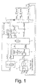
- a simplified one The control scheme according to the invention for these sinusoidal variables is shown in FIG. 1 shown.
- an intermediate circuit voltage regulator 1 generates a target current I ZK-n .
- This target current I ZK-n yields when multiplied by an intermediate circuit voltage U ZK or a target value of the intermediate circuit voltage U ZK-n is a nominal power P ZK-n which is to be obtained from the network side.
- This target power is fed to a calculation device 2.
- the grid current setpoint pointer I Ns and the inverter setpoint voltage pointer U WRi are then transformed into the time domain in a transformation device 3 using the inverse Fourier transform or IFT, resulting in a grid current setpoint i Ns (t) and an inverter setpoint voltage u WRi-s (t) , Furthermore, a mains current control device 4 is implemented in the time domain and has the task of leading a mains current i N (t) to its sinusoidal mains current setpoint i Ns (t). The grid current control device 4 corrects the nominal inverter voltage u WRi-s (t) in the event of parameter changes, for example in the event of a temperature dependence of the grid choke.
- mains current control device 4 By implementing the mains current control device 4 in the time domain, direct current or DC components in the mains current are avoided, provided that they are not already present in the mains current setpoint i Ns (t). Mains voltage harmonics are also applied to the inverter set voltage u WRi-s (t).
- dynamic filter device for intermediate circuit voltages device for Setpoint specification of the DC link voltage when starting the system or Idling problems
- device for dead time compensation of mains voltage harmonics which, however, are described separately below their functions are explained.
- the intermediate circuit voltage regulator 1 is used to calculate the required target power P ZK-n from the generated intermediate circuit target current I ZK-n and the intermediate circuit voltage U ZK . From this target power P ZK-n , a mains current setpoint pointer I Ns is calculated in the computing device together with the mains voltage pointer U N.
- the line current i N should normally be in phase or in phase opposition to the line voltage.
- I N-qsoll a capacitive or inductive current component is required in an exceptional situation , this is specified via I N-qsoll by a higher-level control device, which will not be discussed further here.
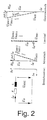
- inverter setpoint voltage pointer U WRi a grid current pointer I N is formed by the calculation device , as shown in FIG. 2.
- the phase current and amplitude of the network current pointer I N can be regulated via the pointer relationship between the network voltage pointer U N and the inverter sum voltage pointer U WR ⁇ .
- the control in the control system 5 is based on a pointer control.
- the controlled system device 5 therefore carries out a transformation of network-frequency variables and maps them as DC or DC variables in the network-frequency coordinate system.
- This has the advantage that the regulation of DC variables is particularly simple.
- the discrete Fourier transform (DFT) is preferably used in the control system device 5 to transform the measured variables, for example the line voltage u N (t).
- a transformation with e -j ⁇ GS t into a network-frequency coordinate system could also be carried out, in which all time variables, including harmonics, are transformed into the same coordinate system, fundamental vibrations are mapped as DC variables and harmonics continue to occur, but with a different frequency.
- this transformation process is not described here.
- the control reacts accordingly "restlessly" to the harmonics.
- the DFT is here preferred transformation process.
- a well-known at DFT Method for influencing DC link fluctuations the harmonics set in the mains current.
- the input functions are ideally scanned synchronously with the network frequency.
- the integration over a period becomes a summation over N sampling points.
- N is the number of samples per fundamental period.
- the controlled system device 5 Since the DFT carries out a summation over a period, the controlled system device 5 does not immediately jump to the entrance react. It requires a period to reach the stationary end value to reach.
- the fundamental oscillation network voltage pointer U N-GS , the network voltage setpoint pointer I Ns and the inverter target voltage pointer U WRi are transformed back from the frequency domain into the time domain with the aid of the inverse Fourier transformation or IFT.
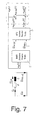
- the controlled system device 5 which is shown in FIG. 3 in the form of a block diagram, includes, among other things, a "phase locked loop" control loop or PLL control loop 5a.
- the grid-side inverter is synchronized with the grid frequency so that it can generate a sinusoidal current that is synchronous with the grid frequency.
- the sinusoidal mains voltage of the frequency ⁇ N is multiplied by the cosine of the PLL frequency ⁇ n to be tracked, taking into account the phase position.
- the PLL control circuit 5a must therefore be limited to a specific frequency range so that it only "snaps" onto the fundamental vibration.
- the PLL control loop 5a and the DFT 5b of the fundamental wave are shown in FIG. 3.
- the PLL control loop 5a is a closed control loop, which is an averager X instead of integration.
- phase jump in the mains voltage a time delay and a settling of the output variable occur.
- a phase jump in the line voltage can be generated, for example, by shedding a load of a second locomotive on the same line section with a partly common line impedance. The effect would be a mains current that is not in phase with the mains voltage during this time, which is classified as uncritical here.
- a jump in amplitude in the mains voltage can also be caused by a load shedding of a second locomotive.
- the DC link voltage regulator 1 will now be discussed in more detail below.
- the intermediate circuit voltage regulator 1 pre-controls a load current I ZK-m or I L from the intermediate circuit.
- the load current I L which is taken from the intermediate circuit on the motor side, is fed to the intermediate circuit voltage regulator 1 and is added directly, almost instantaneously, to the desired value I C of an intermediate circuit voltage regulating unit 1a by an addition device 1b.
- the network-side control already requires a power P ZK before the intermediate circuit voltage U ZK has dropped.
- the load current I L can be determined in various ways, but these are not shown, for example by calculation by the motor control or by indirect measurement, for example, of the pulsed intermediate circuit current, very good filtering with a correspondingly large dead time being required.
- the device according to the invention is designed such that a DC share in the grid current is avoided, which is necessary for the transformers do not saturate in the substations.
- the mains current control device 4 is realized in the time domain. Due to the realization in the time domain, the Mains current control device 4 in principle capable of a DC component in the mains currentenfinregeln. Even very small DC currents are or I component recorded and corrected. All you have to do is ensure that the current detection and the analog-digital or AD conversion are accurate are enough.
- the DC component i N-DC in the mains current setpoint i Ns can be compensated for by suitable filtering.
- the mains current control device 4 according to the invention with regulation of the DC component i N-DC in the mains current setpoint i Ns is shown in FIG. 6 in the form of a block diagram.
- the mains current control device 4 comprises a flowing mean value filter 4a and a PI control device 4b connected downstream of it.
- the DC component i N-DC in the mains current setpoint i Ns is determined by the mains current control device 4 via the flowing mean value filter 4a.
- the flowing mean value filter 4a sums up all the time-discrete values of the mains current setpoint i Ns over one (or more) periods. If there are otherwise only line frequency components in the line current setpoint i Ns , the exact DC component i N-DC of the line current setpoint i Ns is determined after just one period.
- a device for supply voltage 6 is also formed, the block diagram of which is shown in FIG. 7.
- This device for supply voltage 6 has the task of relieving the supply current control device 4 at supply voltage harmonics.
- a compensation determination device 7a is designed for precalculating the grid voltage u NV (t) to be controlled.
- the control concept implemented by this device for supplying mains voltage 6 is based on pointer control of the fundamental oscillation quantities.
- the goal is a sinusoidal current without harmonics. This is true if the voltage drop U LN across the line choke contains only a fundamental component.
- the harmonics in the grid voltage U N-OS and in the short-term mean value of the inverter total voltage U WR-n ⁇ -OS must be the same. This will be achieved by applying the mains voltage harmonics to the total inverter voltage.
- the processing time can be just before scanning and processing Transfer of the next degree of modulation to the PWM can be reduced.
- the dead time of the PWM cannot be reduced with a scan control.
- the error voltage amplitude at 83 ms dead time is at 15kV / 16.7 Hz network shown in Fig. 8.
- the large error cannot be accepted with this dead time.
- the error is greater than the mains voltage harmonic • ⁇ U N-nOS •, which should also be compensated, at least partially, at this frequency.
- the first option with DFT / IFT is conventional with high transformer leakage inductance used. Here only the fundamental, the third and fifth Harmonic considered.
- FIGS Dead time compensation a block diagram of an inventive Mains voltage connection with dead time explained in more detail.
- the dead time compensation by the device for dead time compensation 7 is intended to perform the task of estimating a future mains voltage value u NV (t).
- the device for dead time compensation 7 adds a small estimated value ⁇ u comp (t) to the instantaneous value of the mains voltage u N (t), which is obtained from experience with the last periods.
- the estimated value ⁇ u comp (t) is periodic in the case of stationary signals and can therefore be obtained from the voltages u N ((kN) T) of the last period by the compensation determination device 7a. 9 is T the sampling time, N the number of samples per network period and k indicates the respective sampled instantaneous value.
- a filter device 8 can be formed after this by the compensation determination device 7a, which alone is sufficient for the dead time compensation.
- 8 values are stored in the filter device over several network periods and a flowing averaging is carried out over several periods.
- the filtered estimated value ⁇ u comp (t) is then added to the instantaneous value of the mains voltage u N (t). Subsequently, the resulting supply voltage u NV (t) to be controlled is fed to the device for supply voltage connection 6 which has a dead time.
- the mains voltage u N contains strong harmonics in this example.
- the voltage ⁇ u comp is shown, which results from the differential voltage of the mains voltage of two successive sampling times and is determined by the compensation determination device 7a.
- the voltage ⁇ u comp is also periodic.
- the voltage ⁇ u k-fil contains the averaging over 4 values, one for each period, which are identified in FIG. 11 by o and *.
- the line voltage u NV to be controlled results from the addition of the current line voltage u N and the voltage ⁇ u k-fil , which is formed by the compensation determination device 7a and the filter device 8 from the line voltage of the last periods.
- the compensation determination device 7a shown in FIG. 10 The calculation performed is illustrated below using some examples.
- a 16.7 Hz network was assumed.
- the filtering is carried out over 4 periods.
- the effectiveness of the activation decreases with frequency due to the asynchronous sampling.
- the error due to the scanning is very small on the one hand, and on the other hand, cause-related harmonic harmonics, for example from vehicles with phase synchronous phase control, are to be expected.
- the dead time compensation places high demands the accuracy of the sampling or the synchronization of the PLL control loop:
- the accuracy should be at e.g. 1 Hz, this corresponds to an accuracy of 1 Hz / 33 during synchronization to the 16.7 Hz fundamental (corresponding to 0.18%).
- the dead time compensation only up to the lower kHz range brings advantages.
- the device for supply voltage 6 with device for dead time compensation 7 should therefore have a low-pass filter device (not shown) be designed at the input, which the high frequencies from a few kHz filters out.
- the exact design of the maximum usable frequency can only be started a specific application.
- the dead time compensation found a good and dynamic solution. Down to the lower kHz range an increase in input impedance is expected.
- the transmission of harmonics from the intermediate circuit voltage U ZK to the mains current setpoint I Ns can be shown very clearly on the corresponding control path.
- the DC link voltage regulator 1 with PI control converts a harmonic in the DC link voltage U ZK into a phase-shifted harmonic of the same frequency in the power request P ZK-s or in the mains current setpoint pointer I Ns .
- the IFT, ie the transformation into the time domain there are harmonics in the mains current setpoint i Ns (t).
- a fourth harmonic in the intermediate circuit voltage U ZK generates a phase-shifted fourth harmonic in the power requirement P ZK-ns (t).
- the mains current setpoint of the mains current setpoint pointer I Ns is proportional to the power requirement P ZK-ns and therefore also contains a fourth harmonic.
- P ZK-ns ( t ) P ZK-DC + P ZK -4 Sin (4 ⁇ t + ⁇ )
- I ns I N - DC + I N -4 Sin (4 ⁇ t + ⁇ )
- i ns ( t ) ⁇ I N - DC + I N -4 Sin (4 ⁇ t + ⁇ ) ⁇ ⁇ sin ( ⁇ t )
- i ns ( t ) I N - DC Sin ( ⁇ t ) + I N -4 2 * Sin (3 ⁇ t ) + I N -4 2 * Sin (5 ⁇ t )
- a second harmonic in the intermediate circuit voltage U ZK generates a phase-shifted second harmonic in the power requirement P ZK-ms (t). Together with the basic oscillation requirement of the mains current, this results in a first and third harmonic in the nominal value of the mains current.
- the harmonics must be filtered out so that harmonics in the intermediate circuit voltage U ZK are not transferred to the mains current I N. This should not be achieved with a low-pass filter, as dynamic DC link voltage changes due to load jumps should be compensated for without dead time if possible.
- a dynamic filter device 9 is therefore formed, in which the harmonics are filtered and then subtracted from the actual value of the intermediate circuit voltage U ZK .
- the second, fourth, sixth, etc. harmonics are to be filtered from the intermediate circuit voltage U ZK , special emphasis being placed on filtering the fourth harmonic, since this significantly influences the intermediate circuit power due to its dominance in the voltage.
- the dynamic filter device 9 according to a first exemplary embodiment of the invention is constructed as shown in FIG. 17A and implemented in a sampling control device (not shown).
- the intermediate circuit voltage U ZK (t) here an intermediate circuit voltage in which only 2n-fold harmonics are taken into account, is fed to a DFT transformation device 10a.
- the 2nd to 2nth harmonics of the intermediate circuit voltage U 2n-ist are thus filtered out from the resulting intermediate circuit voltage U 2n-fil .
- 17B shows harmonics from past network periods be calculated.
- This second method according to the invention and its The structure in the block diagram is analyzed in more detail below.
- a dynamic filter device 9 as shown in FIG. 17B, is implemented in the scan control device (not shown).
- a flowing averaging U ZK-mi (t) is carried out over half a network period, corresponding to N 2 samples, by an averager 11a. From the second harmonic, all straight harmonics are thus filtered out, as shown in the signal profiles according to FIGS. 18 and 19. This results from the fact that the integral becomes zero over a half-period at a double or 2n-fold harmonic.
- the harmonics U ZK-OS (t) are obtained by subtracting the flowing mean U ZK-mi (t) determined by the averager 11a from the actual value U ZK (t).
- the harmonics U ZK-OS (t) are then filtered in a filter device 11b, which is similar to a so-called comb filter. With this filter device 11b, however, it should be noted that the 2n-fold harmonics are not impaired. For this reason, a flowing mean value filter device is proposed, which has a separate mean value filter for each value of a half period. The filter device 11b forms the flowing mean value over N fil values, one value per half network period and at the corresponding point of the other half periods.
- U ZK-OS ( kT ) U ZK ( kT ) - U ZK - Wed. ( kT )
- U ZK-fil ( kT ) U ZK ( kT ) - U ZK-OS-fil ( kT )
- This device according to the invention and the method according to the invention bring for all relevant harmonics, especially the fourth harmonic and the lower, second, sixth and eighth harmonics good results.
- U N-3OS 20%
- U N-GS U N-9OS 5.0%
- U N-GS U N-5OS 8.5%
- U N-GS U N-11OS 4.5%
- U N-GS U N-7OS 7.5%
- the intermediate circuit voltage U ZK contains strong harmonics in both cases. Without the device according to the invention for regulating an intermediate circuit voltage on the network side (left-hand illustration in FIG. 20), these go directly into the power requirement P ZK of the intermediate circuit voltage regulating device and are transferred to the nominal value of the mains current.
- the mains current i N (t) contains very high harmonics.
- the distorted intermediate circuit voltage U ZK (right in FIG. 20) is filtered very well in U ZK-fil .
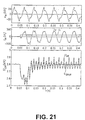
- the filter algorithm only filters out the harmonics with even multiples of the mains frequency and therefore hardly any dynamics are lost in the event of load jumps, as can be seen from FIG. 21.
- the power requirement P ZK of the DC link voltage regulator hardly contains any harmonics.
- Correspondingly few harmonics are contained in the mains current i N (t).
- the dynamic behavior of the device according to the invention and of the method according to the invention is also very good.
- 21 shows the dynamics using the example of a load jump with distorted mains voltage.
- the device according to the invention and the method according to the invention thus practically no dynamics are lost in the regulation of the intermediate circuit voltage U ZK .
- FIG. 22 there are also signal curves of a direct mains voltage pre-control with and without dead time compensation according to the invention by the device shown for dead time compensation 7.
- the same mains voltage distortions become again as assumed in Fig. 20.
- Even the dynamic one Filter device 9 was used.
- the device according to the invention has, among other things DC link voltage regulator 1 for determining a power requirement, a calculation device 2 for calculating an inverter target voltage pointer and a mains current setpoint pointer, a transformation device 3 to transform these pointers into the time domain, a mains current control device 4, a controlled system device 5 for determining and controlling a mains voltage fundamental wave pointer and a mains frequency, one Device for supplying mains voltage and a dynamic filter device.
- the mains current control device 4 regulates a DC component in the mains current by compensating it with suitable filtering.
- the facility for Mains voltage connection relieves the mains current control device 4 Mains voltage harmonics by adding mains voltage harmonics the inverter total voltage are applied.
- the dynamic The filter device is located at the entrance to the device for network-side regulation an intermediate circuit voltage, filters the even harmonic of the Fundamental from the DC link voltage and then subtracts it from the actual value of the DC link voltage.
Landscapes
- Engineering & Computer Science (AREA)
- Power Engineering (AREA)
- Life Sciences & Earth Sciences (AREA)
- Sustainable Development (AREA)
- Sustainable Energy (AREA)
- Transportation (AREA)
- Mechanical Engineering (AREA)
- Inverter Devices (AREA)
- Dc-Dc Converters (AREA)
- Emergency Protection Circuit Devices (AREA)
- Details Of Television Scanning (AREA)
- Generation Of Surge Voltage And Current (AREA)
Abstract
Description
Die vorliegende Erfindung bezieht sich auf eine Einrichtung und ein Verfahren zur netzseitigen Regelung von Spannungen, insbesondere von Zwischenkreisspannungen.The present invention relates to an apparatus and a method for the network-side regulation of voltages, especially of intermediate circuit voltages.
Herkömmlich kann unter den Voraussetzungen, dass Harmonische in einer Zwischenkreisspannung keine Auswirkung auf den Netzstrom haben, d.h. eine Netzregelung nicht auf Zwischenkreis-Harmonische reagiert, und dass ein Motor eine konstante Leistung bezieht, eine Netzleistung als bekannt vorausgesetzt werden. Netzspannungsverzerrungen wirken sich jedoch negativ auf den Zwischenkreis aus. Insbesondere beeinflusst die vierte Harmonische die Zwischenkreisleistung. Während die vierte Harmonische in der Leistung wesentlich kleiner als die zweite Harmonische ist, dominiert die vierte Harmonische aber in der Spannung und ist die wesentliche Auslegungsgrösse des Zwischenkreises. Daher ist es erforderlich, Netz-Harmonische zu berücksichtigen.Conventionally, under the conditions that harmonics in a DC link voltage have no effect on the mains current, i.e. a Line control does not respond to DC link harmonics and that a motor obtains constant power, assuming network power is known become. Mains voltage distortions have a negative effect on the DC link out. In particular, the fourth harmonic influences the DC link power. While the fourth harmonic is essential in performance is smaller than the second harmonic, but the fourth harmonic dominates in voltage and is the main design variable of the DC link. It is therefore necessary to take harmonics into account.
Die zweite Harmonische in der Zwischenkreisleistung erzeugt dahingegen aufgrund einer niedrigen Impedanz in diesem Frequenzbereich nur eine sehr kleine zweite Harmonische in der Zwischenkreisspannung. Daher ist im Fall einer Netzspannung ohne Oberschwingungen die Zwischenkreisspannungsschwankung durch die zweite Harmonische vernachlässigbar klein.In contrast, the second harmonic in the DC link power generates only a very low due to a low impedance in this frequency range small second harmonic in the DC link voltage. Therefore, in the case of one Mains voltage without harmonics the DC link voltage fluctuation negligibly small due to the second harmonic.
Jedoch besteht bei herkömmlichen Einrichtungen das Problem der Netzrückwirkungen im Netzstrom.However, there is the problem of network perturbations in conventional devices in the mains current.
Daher ist es Aufgabe der vorliegenden Erfindung, eine Einrichtung sowie ein Verfahren zur stabilen, schwingungsfreien netzseitigen Regelung einer Zwischenkreisspannung auszubilden. It is therefore an object of the present invention, a device and a Method for stable, vibration-free regulation of an intermediate circuit voltage on the network side train.
Diese Aufgabe wird durch eine Einrichtung mit den Merkmalen des Patentanspruchs 1 sowie durch ein Verfahren mit den Merkmalen des Patentanspruchs 8 gelöst. In den Unteransprüchen sind vorteilhafte Weiterbildungen der Erfindung angegeben.This object is achieved by a device with the features of the patent claim 1 and by a method with the features of the claim 8 solved. Advantageous developments of the invention are in the subclaims specified.
Erfindungsgemäss entstehen weiterhin Harmonische im Zwischenkreis, die bei Netzspannungs-Harmonischen toleriert werden müssen, jedoch werden durch die erfindungsgemässe Einrichtung und das erfindungsgemässe Verfahren die Netzrückwirkungen gegenüber dem Stand der Technik wesentlich reduziert und es wird eine stabile netzseitige Regelung einer Zwischenkreisspannung möglich.According to the invention, harmonics continue to occur in the intermediate circuit Mains voltage harmonics must be tolerated, however, by the device according to the invention and the method according to the invention Network interference significantly reduced compared to the prior art and it becomes a stable network-side regulation of an intermediate circuit voltage possible.
Diese und weitere Merkmale, Aufgaben und Vorteile der vorliegenden Erfindung werden aus der nachstehenden Beschreibung eines bevorzugten Ausführungsbeispiels der Erfindung in Verbindung mit der Zeichnung offensichtlich.These and other features, objects, and advantages of the present invention will become apparent from the following description of a preferred embodiment of the invention in connection with the drawing.
Es zeigen:
Herkömmlich ist ein Zwischenkreis zwischen das Netz und einen Motor geschaltet. Eine Vorrichtung zur netzseitigen Regelung einer Zwischenkreisspannung passt eine vom Netz bezogene Leistung an die vom Motor geforderte Leistung an. Eine Differenz zwischen bezogener und abgegebener Leistung ändert den Zwischenkreisspannungswert. Gleichzeitig ist ein sinusförmiger Netzstrom gefordert. Bei der Regelung soll im Normalfall der Netzstrom in Phase zur Netzspannung geregelt werden bzw. beim Rückspeisen in Gegenphase. Nur in Ausnahmefällen ist eine Phasenverschiebung zwischen Netzstrom und Netzspannung gefordert.An intermediate circuit is conventionally connected between the network and a motor. A device for regulating an intermediate circuit voltage on the network side adjusts a power drawn from the network to that required by the motor Performance. A difference between purchased and delivered power changes the DC link voltage value. At the same time is a sinusoidal Mains power required. In the regulation, the mains current should normally be in phase be regulated to the mains voltage or when regenerating in the opposite phase. Only in exceptional cases is there a phase shift between the mains current and mains voltage required.
Um die Netzrückwirkungen bei verzerrter Netzspannung klein zu halten, muss der Einfluss der unvermeidbaren Oberschwingungen in der Zwischenkreisspannung auf die Netzstromregelung minimiert werden. In order to keep the network perturbations small when the mains voltage is distorted, the influence of the inevitable harmonics in the DC link voltage to be minimized to the mains current regulation.
Daher ist erfindungsgemäss eine Vorrichtung sowie ein Verfahren zur netzseitigen Regelung der Zwischenkreisspannung ausgebildet, die die folgenden Aufgaben erfüllt:
- Regelung von Zwischenkreisspannungen, die weitgehend unabhängig von der Belastung der Motorseite sein sollen.
- Netzrückwirkungsarmer Bezug/Abgabe der geforderten Antriebsleistung mit sinusförmigem Strom, der in Phase/Gegenphase zur Netzspannung ist. Nur in Sonderfällen, die hier nicht weiter berücksichtigt werden, ist ein zur Netzspannung phasenverschobener Strom gefordert, z.B. ein kapazitiver Strom zur Stützung der Netzspannung).
- Regulation of intermediate circuit voltages, which should be largely independent of the load on the motor side.
- Supply / delivery of the required drive power with sinusoidal current that is in phase / counter phase to the mains voltage with little feedback. Only in special cases, which are not considered further here, is a current out of phase with the mains voltage is required, eg a capacitive current to support the mains voltage).
Um die erste Forderung, d.h. die Regelung der Zwischenkreisspannung, zu erfüllen, muss die netzseitig bezogene Leistung an die motorseitig abgegebene Leistung angepasst werden. Eine Differenz zwischen abgegebener Leistung und bezogener Leistung ändert die Zwischenkreisspannung, da ein Zwischenkreiskondensator aufgeladen oder entladen wird. Eine Einrichtung zur netzseitigen Regelung der Zwischenkreisspannung passt daher automatisch die netzseitig bezogene Leistung an die motorseitig abgegebene Leistung an. Beim Rekuperieren bzw. elektrisches Abbremsen des Fahrzeugs beispielsweise ist der Leistungsfluss umgekehrt, der Zwischenkreis bezieht eine Leistung vom Motor, welche in das Netz zurückgespeist wird.For the first claim, i.e. the regulation of the intermediate circuit voltage, the power drawn on the network side must be delivered to the motor side Performance can be adjusted. A difference between the output and related power changes the intermediate circuit voltage because of an intermediate circuit capacitor being charged or discharged. A facility for the network side Regulation of the intermediate circuit voltage therefore automatically adjusts the line side related power to the power output on the motor side. At the Recuperation or electrical braking of the vehicle is for example the power flow is reversed, the DC link draws power from the motor, which is fed back into the network.
Die erfindungsgemässe Einrichtung zur Regelung der sinusförmigen Grössen der Zwischenkreisspannung verwendet eine Zeigerregelung. Ein vereinfachtes erfindungsgemässe Regelungsschema dieser sinusförmigen Grössen ist in Fig. 1 gezeigt. Im Beispiel werden N=12 seriengeschaltete Sub-Stromrichter verwendet. Herkömmlich wird lediglich der Fall N=1 realisiert, in dem es keine Serienschaltung gibt.The device according to the invention for regulating the sinusoidal variables the DC link voltage uses a pointer control. A simplified one The control scheme according to the invention for these sinusoidal variables is shown in FIG. 1 shown. In the example, N = 12 series-connected sub-converters are used. Conventionally, only the case N = 1 is realized, in which there is no series connection gives.
Gemäss diesem Regelungsschema generiert ein Zwischenkreisspannungsregler 1 einen Sollstrom IZK-n. Dieser Sollstrom IZK-n ergibt bei Multiplikation mit einer Zwischenkreisspannung UZK oder einem Sollwert der Zwischenkreisspannung UZK-n eine Soll-Leistung PZK-n, die von der Netzseite bezogen werden soll. Diese Soll-Leistung wird einer Berechnungseinrichtung 2 zugeführt. In der Berechungseinrichtung 2 wird dann mit Hilfe eines Grundschwingungszeigerdiagramms aus der Soll-Leistung PZK-n und einem Netzspannungsgrundschwingungszeiger U N-GS ein Netzstromsollwertzeiger I N-s und ein Wechselrichtersollspannungszeiger U WRi (i = 1, 2, ..., n) berechnet. Anschliessend werden der Netzstromsollwertzeiger I N-s und der Wechselrichtersollspannungszeiger U WRi in einer Transformationseinrichtung 3 unter Verwendung der Inversen Fourier-Transformation bzw. IFT in den Zeitbereich transformiert, wobei sich ein Netzstromsollwert iN-s(t) und eine Wechselrichtersollspannung uWRi-s(t) ergeben. Weiterhin ist eine Netzstromregeleinrichtung 4 im Zeitbereich realisiert und hat die Aufgabe einen Netzstrom iN(t) auf seinem sinusförmigen Netzstromsollwert iN-s(t) zu führen. Die Netzstromregeleinrichtung 4 korrigiert die Wechselrichtersollspannung uWRi-s(t) bei Parameteränderungen, z.B. bei Temperaturabhängigkeit der Netzdrossel. Durch die Realisierung der Netzstromregeleinrichtung 4 im Zeitbereich werden unter anderem Gleichstrom- bzw. DC-Anteile im Netzstrom vermieden, vorausgesetzt, dass sie nicht schon im Netzstromsollwert iN-s(t) vorhanden sind. Weiterhin werden Netzspannungsoberschwingungen auf die Wechselrichtersollspannung uWRi-s(t) aufgeschaltet.According to this control scheme, an intermediate circuit voltage regulator 1 generates a target current I ZK-n . This target current I ZK-n yields when multiplied by an intermediate circuit voltage U ZK or a target value of the intermediate circuit voltage U ZK-n is a nominal power P ZK-n which is to be obtained from the network side. This target power is fed to a calculation device 2. In the calculation device 2, a grid current setpoint pointer I Ns and an inverter setpoint voltage pointer U WRi (i = 1, 2,..., N) are then calculated from the target power P ZK-n and a grid voltage fundamental oscillation pointer U N-GS with the aid of a basic oscillation pointer diagram . The grid current setpoint pointer I Ns and the inverter setpoint voltage pointer U WRi are then transformed into the time domain in a transformation device 3 using the inverse Fourier transform or IFT, resulting in a grid current setpoint i Ns (t) and an inverter setpoint voltage u WRi-s (t) , Furthermore, a mains current control device 4 is implemented in the time domain and has the task of leading a mains current i N (t) to its sinusoidal mains current setpoint i Ns (t). The grid current control device 4 corrects the nominal inverter voltage u WRi-s (t) in the event of parameter changes, for example in the event of a temperature dependence of the grid choke. By implementing the mains current control device 4 in the time domain, direct current or DC components in the mains current are avoided, provided that they are not already present in the mains current setpoint i Ns (t). Mains voltage harmonics are also applied to the inverter set voltage u WRi-s (t).
In dem in Fig. 1 gezeigten vereinfachten erfindungsgemässen Regelschema sind aus Gründen der Vereinfachung die folgenden Elemente nicht gezeigt: dynamische Filtereinrichtung für Zwischenkreisspannungen, Einrichtung zur Sollwertvorgabe der Zwischenkreisspannung beim Aufstarten der Anlage oder Leerlaufproblematik, Einrichtung zur Totzeitkompensation von Netzspannungsoberschwingungen, die jedoch im folgenden separat beschrieben und ihre Funktionen erläutert werden.In the simplified control scheme according to the invention shown in FIG. 1 For reasons of simplification, the following elements are not shown: dynamic filter device for intermediate circuit voltages, device for Setpoint specification of the DC link voltage when starting the system or Idling problems, device for dead time compensation of mains voltage harmonics, which, however, are described separately below their functions are explained.
Im folgenden wird zunächst die Funktion der Berechungseinrichtung 2 gemäss Fig. 1 näher beschrieben, insbesondere auf die für die Berechnung verwendeten Grundschwingungszeigerdiagramme gemäss Fig. 2 eingegangen. Im Fig. 2 ist ein Fall für N=12 seriengeschaltete Stromrichter gezeigt. In the following, the function of the calculation device 2 according to Fig. 1 described in more detail, in particular on those used for the calculation Basic oscillation pointer diagrams according to FIG. 2. In Fig. 2 shows a case for N = 12 series-connected converters.
Mit Hilfe des Grundschwingungszeigerdiagramms werden der Netzstromsollwertzeiger
I N-s und die Wechselrichtersollspannungszeiger U WRi-s (i = 1, 2, ..., N)
bestimmt. Der Zwischenkreisspannungsregler 1 dient zur Berechnung der geforderten
Soll-Leistung PZK-n aus dem generierten Zwischenkreissollstrom IZK-n und
der Zwischenkreisspannung UZK. Aus dieser Soll-Leistung PZK-n wird in der Berechnungseinrichtung
zusammen mit dem Netzspannungszeiger U N ein Netzstromsollwertzeiger
I N-s berechnet. Der Netzstrom iN soll im Normalfall in Phase bzw. in
Gegenphase zur Netzspannung liegen. Wird in einer Ausnahmesituation ein
kapazitiver oder induktiver Stromanteil gefordert, so wird dieser über IN-qsoll von
einer übergeordneten Regeleinrichtung, auf die hier nicht weiter eingegangen
wird, vorgegeben. Über das Grundschwingungszeigerdiagramm ergibt
sich der Sollwert eines Wechselrichtersummenspannungszeiger U WRΣ. Unter der
Bedingung, dass U N in Phase mit I N ist, gilt:
Aus dem Wechselrichtersummenspannungszeiger U WRΣ kann die Berechnungseinrichtung
2 sehr einfach einen einzelnen Wechselrichtersollspannungszeiger
U WRi von N in Serie geschalteten Wechselrichtern berechnen.
Aus dieser Stellgrösse Wechselrichtersollspannungszeiger U WRi wird durch die Berechnungseinrichtung, wie in Fig. 2 gezeigt, ein Netzstromzeiger I N gebildet. Mittels des von der Regelstreckeneinrichtung 5 ausgegebenen Grundschwingungsnetzspannungszeigers U N-GS kann über die Zeigerbeziehung zwischen Netzspannungszeiger U N und Wechselrichtersummenspannungszeiger U WRΣ der Netzstromzeiger I N in der Phasenlage und Amplitude geregelt werden. From this manipulated variable, inverter setpoint voltage pointer U WRi , a grid current pointer I N is formed by the calculation device , as shown in FIG. 2. By means of the basic oscillation network voltage pointer U N-GS output by the controlled system device 5, the phase current and amplitude of the network current pointer I N can be regulated via the pointer relationship between the network voltage pointer U N and the inverter sum voltage pointer U WRΣ .
Nachfolgend wird nun die Funktion der Regelstreckeneinrichtung 5 detaillierter beschrieben.The function of the controlled system device 5 will now be described in more detail below described.
Die Regelung in der Regelstreckeneinrichtung 5 basiert auf einer Zeigerregelung. Daher führt die Regelstreckeneinrichtung 5 eine Transformation netzfrequenter Grössen durch und bildet sie als Gleichstrom- bzw. DC-Grössen im netzfrequenten Koordinatensystem ab. Dies hat den Vorteil, dass die Regelung von DC-Grössen besonders einfach ist. Zur Transformation der Messgrössen von z.B. der Netzspannung uN(t) wird in der Regelstreckeneinrichtung 5 bevorzugt die Diskrete Fourier-Transformation (DFT) verwendet. Alternativ könnte auch eine Transformation mit e-jωGSt in ein netzfrequentes Koordinatensystem erfolgen, bei der alle Zeitgrössen, auch Oberschwingungen, in dasselbe Koordinatensystem transformiert werden, Grundschwingungen als DC-Grössen abgebildet werden und Oberschwingungen weiterhin auftreten, jedoch mit einer anderen Frequenz. Dieses Transformationsverfahren wird hier jedoch nicht beschrieben. Zudem reagiert die Regelung bei der Verwendung dieses Verfahrens entsprechend "unruhig" auf die Oberschwingungen.The control in the control system 5 is based on a pointer control. The controlled system device 5 therefore carries out a transformation of network-frequency variables and maps them as DC or DC variables in the network-frequency coordinate system. This has the advantage that the regulation of DC variables is particularly simple. The discrete Fourier transform (DFT) is preferably used in the control system device 5 to transform the measured variables, for example the line voltage u N (t). Alternatively, a transformation with e -jω GS t into a network-frequency coordinate system could also be carried out, in which all time variables, including harmonics, are transformed into the same coordinate system, fundamental vibrations are mapped as DC variables and harmonics continue to occur, but with a different frequency. However, this transformation process is not described here. In addition, when using this method, the control reacts accordingly "restlessly" to the harmonics.
Bei der Diskreten Fourier-Transformation bzw. DFT werden alle Oberschwingungen separat berechnet. Im Idealfall, z.B. bei netzsynchroner Abtastung, sind die Amplituden des Spektrums konstant, d.h. stellen in der Regelung DC-Grössen dar. Wenn auch Oberschwingungen einzeln geregelt werden sollen, müssen alle zu regelnden Frequenzen einzeln transformiert werden.In the Discrete Fourier Transform or DFT, all harmonics calculated separately. Ideally, e.g. with synchronous scanning, the amplitudes of the spectrum are constant, i.e. in the regulation are DC variables If harmonics are also to be regulated individually, all frequencies to be controlled must be transformed individually.
Bei dem verzerrten Bahnnetz sind beispielsweise starke Oberschwingungsanteile in der Netzspannung zu erwarten. Aus diesem Grund ist hier die DFT das bevorzugte Transformationsverfahren. Zudem kann bei der DFT ein bekanntes Verfahren zur Beeinflussung von Zwischenkreisschwankungen, das Oberschwingungen im Netzstrom einstellt, angewendet werden. In the distorted rail network, for example, there are strong harmonic components expected in the mains voltage. For this reason, the DFT is here preferred transformation process. In addition, a well-known at DFT Method for influencing DC link fluctuations, the harmonics set in the mains current.
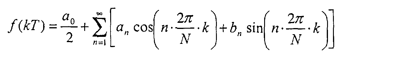
Mit Hilfe der DFT lassen sich periodische Funktionen in ihre Teilschwingungen
zerlegen. Eine Fourierreihe ist durch den folgenden Ansatz gegeben:

Dabei sind die Koeffizienten durch folgende Gleichungen gegeben:


Bei einem abgetasteten System, wie bei der erfindungsgemässen Regelung,
werden die Eingangsfunktionen im Idealfall synchron zur Netzfrequenz abgetastet.
Aus der Integration über eine Periode wird eine Summation über N-Abtastpunkte.
N ist die Anzahl von Abtastungen pro Grundschwingungsperiode.


Da bei der DFT eine Summation über eine Periode durchgeführt wird, kann die Regelstreckeneinrichtung 5 nicht sofort auf einen Sprung am Eingang reagieren. Sie benötigt eine Periodendauer um den stationären Endwert zu erreichen. Since the DFT carries out a summation over a period, the controlled system device 5 does not immediately jump to the entrance react. It requires a period to reach the stationary end value to reach.
Anschliessend erfolgt in der Transformationseinrichtung 3 eine Rücktransformation
des Grundschwingungsnetzspannungszeigers U N-GS, des Netzspannungssollwertzeigers
I N-s sowie des Wechselrichtersollspannungszeigers U WRi aus
dem Frequenzbereich in den Zeitbereich mit Hilfe der inversen Fourier-Transformation
bzw. IFT.

Beim abgetasteten System ergeben sich die folgenden Rücktransformationen:
Damit der netzseitige Wechselrichter einen sinusförmigen Strom erzeugen
kann, der synchron zur Netzfrequenz ist, wird er auf die Netzfrequenz synchronisiert.
Dies geschieht in der Regelstreckeneinrichtung 5. Die Regelstreckeneinrichtung
5, die in Fig. 3 in Form eines Blockschaltbilds gezeigt ist, umfasst
unter anderem einen "Phase Locked Loop" -Regelkreis bzw. PLL-Regelkreis 5a.
In dem PLL-Regelkreis 5a erfolgt eine Synchronisation des netzseitigen Wechselrichters
auf die Netzfrequenz, damit er einen sinusförmigen Strom erzeugen
kann, der synchron zur Netzfrequenz ist. In dem PLL-Regelkreis 5a wird die sinusförmige
Netzspannung der Frequenz ωN mit dem Kosinus der nachzuführenden
PLL-Frequenz ωn unter Berücksichtigung der Phasenlage multipliziert.
Eine Integration dieses Produkts liefert genau dann den Wert 0, wenn die Frequenz
und die Phasenlage übereinstimmen. Die Aufgabe der Regelung in
dem PLL-Regelkreis 5a ist es, die Abtastzeit und damit Frequenz und relative
Phasenlage der PLL-Frequenz ωn so zu regeln, dass das Integral 0 wird.
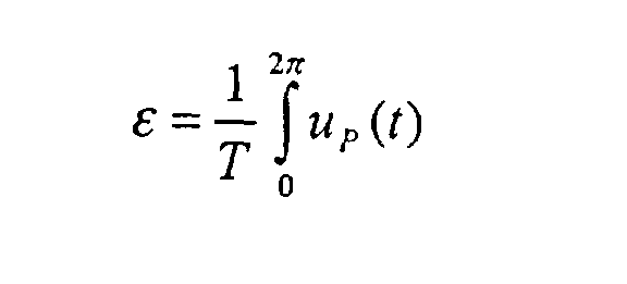
Für den Sonderfall ωn = ωN wird die Funktionsweise leicht ersichtlich:
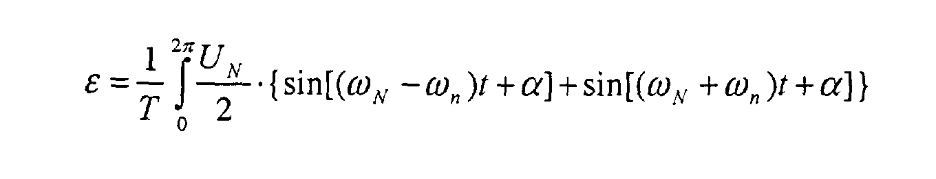
Es wurde ausgenutzt, dass das Integral über eine Periode für alle ganzzahligen Vielfachen der Grundschwingung Null wird. Im obigen Beispiel war dies der Fall für ωn = ωN und α = 0.It has been exploited that the integral becomes zero over a period for all integer multiples of the fundamental. In the example above, this was the case for ω n = ω N and α = 0.
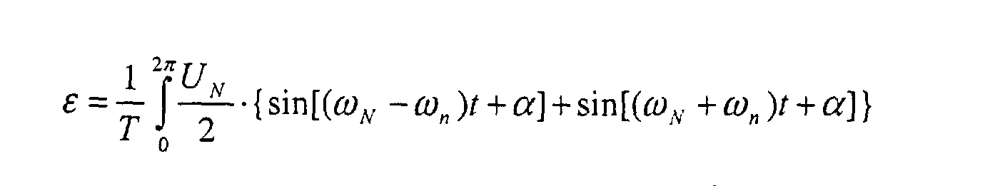
Das Integral wird aber auch für alle ganzzahligen Harmonischen ωn = k · ωN
Null. Dies soll nun am Beispiel von ωn = 2 · ωN gezeigt werden:

Der PLL-Regelkreis 5a muss also auf einen bestimmten Frequenzbereich beschränkt werden, damit sie nur auf die Grundschwingung "einrastet" .The PLL control circuit 5a must therefore be limited to a specific frequency range so that it only "snaps" onto the fundamental vibration.
Es ist noch zu beachten, dass für den Sonderfall ωn = ωN und α = 0 der Imaginärteil
der Grundschwingungsspannung Im{U N-GS} mit obigem Integral E übereinstimmt.

Der PLL-Regelkreis 5a und die DFT 5b der Grundschwingung sind in Fig. 3 gezeigt.
Der PLL-Regelkreis 5a ist ein geschlossener Regelkreis, der einen Mittelwertbildner
Beispielsweise tritt bei einem Phasensprung der Netzspannung eine Zeitverzögerung
und ein Einschwingen des Ausgangsgrösse auf. Ein derartiger Phasensprung
der Netzspannung kann z.B. durch einen Lastabwurf einer zweiten Lokomotive
auf demselben Leitungsabschnitt mit teilweise gemeinsamer
Netzimpedanz erzeugt werden. Die Auswirkung wäre ein Netzstrom, der in
dieser Zeit nicht in Phase mit der Netzspannung ist, was hier als unkritisch eingestuft
wird. Auch ein Amplitudensprung in der Netzspannung kann durch
einen Lastabwurf einer zweiten Lokomotive hervorgerufen werden. In diesem
Fall kommt eine Zeitverzögerung in der DFT 5a durch den Mittelwertbildner
Im folgenden wird nun genauer auf den Zwischenkreisspannungsregler 1 eingegangen. Der Zwischenkreisspannungsregler 1 ist in Fig. 4 separat dargestellt. Er führt eine Vorsteuerung eines Laststromes IZK-m bzw. IL aus dem Zwischenkreis durch. Dazu wird der Laststrom IL, der motorseitig aus dem Zwischenkreis entnommen wird, dem Zwischenkreisspannungsregler 1 zugeführt und durch eine Additionseinrichtung 1b direkt, fast verzögerungsfrei zum Sollwert IC eines Zwischenkreisspannungsregel-einrichtung 1a addiert. Auf diese Weise fordert die netzseitige Regelung bereits eine Leistung PZK, bevor die Zwischenkreisspannung UZK abgesunken ist. Der Laststrom IL kann auf verschiedene Wege bestimmt werden, die jedoch nicht gezeigt sind, beispielsweise durch Berechnung durch die Motorregelung oder durch indirekte Messung z.B, des pulsförmigen Zwischenkreisstromes, wobei eine sehr gute Filterung mit entsprechend grosser Totzeit erforderlich ist.The DC link voltage regulator 1 will now be discussed in more detail below. The intermediate circuit voltage regulator 1 is shown separately in FIG. 4. It pre-controls a load current I ZK-m or I L from the intermediate circuit. For this purpose, the load current I L , which is taken from the intermediate circuit on the motor side, is fed to the intermediate circuit voltage regulator 1 and is added directly, almost instantaneously, to the desired value I C of an intermediate circuit voltage regulating unit 1a by an addition device 1b. In this way, the network-side control already requires a power P ZK before the intermediate circuit voltage U ZK has dropped. The load current I L can be determined in various ways, but these are not shown, for example by calculation by the motor control or by indirect measurement, for example, of the pulsed intermediate circuit current, very good filtering with a correspondingly large dead time being required.
Weiterhin ist die erfindungsgemässe Einrichtung derart ausgebildet, dass ein DC-Anteils im Netzstrom vermieden wird, die erforderlich ist, damit die Transformatoren in den Unterwerken nicht sättigen.Furthermore, the device according to the invention is designed such that a DC share in the grid current is avoided, which is necessary for the transformers do not saturate in the substations.
Diese Funktion wird durch die Netzstromregeleinrichtung 4 durchgeführt, die im Zeitbereich realisiert ist. Aufgrund der Realisierung im Zeitbereich ist die Netzstromregeleinrichtung 4 prinzipiell in der Lage einen DC-Anteil im Netzstrom auszuregeln. Selbst sehr kleine DC-Ströme werden über den Imaginär- bzw. I-Anteil erfasst und ausgeregelt. Dazu muss lediglich sichergestellt sein, dass die Stromerfassung und die Analog-Digital- bzw. AD-Wandlung genau genug sind.This function is carried out by the mains current control device 4 is realized in the time domain. Due to the realization in the time domain, the Mains current control device 4 in principle capable of a DC component in the mains current auszuregeln. Even very small DC currents are or I component recorded and corrected. All you have to do is ensure that the current detection and the analog-digital or AD conversion are accurate are enough.
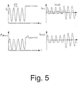
Kritischer ist jedoch die Kompensation eines DC-Anteils iN-DC im Stromsollwert iN-s,
Dies soll am Beispiel der in Fig. 5 gezeigten Signalverläufe, die die Ursache des
DC-Anteils iN-DC im Stromsollwert iN-s und deren Kompensation zeigen, näher erläutert
werden. Hier wird ein Laststrom IL aus dem Zwischenkreis angenommen,
der einen netzfrequenten Anteil enthält. Diese Laststromkomponente
erzeugt über den Zwischenkreisspannungsregler 1 einen netzsynchronen Anteil
in der Leistungsanforderung PZK-n-s aus dem Netz bzw. im Netzstromsollwertzeiger
I N-s. Je nach Phasenlage ergibt sich nach der IFT bereits im Sollwert des
Netzstromes iN-s ein DC-Anteil iN-DC. Dies wird an einem Beispiel deutlich. In diesem
extremen Beispiel wird angenommen, dass der Netzstromsollzeiger I N-s nur
einen netzfrequenten Anteil enthält, der in Phase zur Netzspannung ist. Nach
der Transformation in den Zeitbereich (hierbei entspricht die IFT einer Multiplikation
mit sin(ωNt)) ergibt sich ein DC-Anteil iN-DC im Netzstromsollwert iN-s(t):
Der DC-Anteil iN-DC im Netzstromsollwert iN-s kann durch geeignete Filterung
kompensiert werden. Die erfindungsgemässe Netzstromregeleinrichtung 4 mit
Ausregelung des DC-Anteils iN-DC im Netzstromsollwert iN-s ist in Fig. 6 in Form eines
Blockschaltbilds gezeigt. Hierbei umfasst die Netzstromregeleinrichtung 4
ein fliessendes Mittelwertfilter 4a sowie eine diesem nachgeschaltete PlRegeleinrichtung
4b. Der DC-Anteil iN-DC im Netzstromsollwert iN-s wird durch die
Netzstromregeleinrichtung 4 über das fliessende Mittelwertfilter 4a bestimmt.
Das fliessende Mittelwertfilter 4a summiert hierzu alle zeitdiskreten Werte des
Netzstromsollwerts iN-s über eine (oder mehrere) Perioden auf. Sind ansonsten
nur netzfrequente Komponenten im Netzstromsollwert iN-s vorhanden, ist bereits
nach einer Periode der exakte DC-Anteil iN-DC des Netzstromsollwerts iN-s bestimmt.

Auf diese Weise wird mit der erfindungsgemässen Netzstromregeleinrichtung 4 der DC-Anteil iN-DC des Netzstromsollwerts iN-s zuverlässig ausgeregelt.In this way, the DC component i N-DC of the mains current setpoint i Ns is reliably corrected using the mains current control device 4 according to the invention.
Ausserdem ist bei der erfindungsgemässen Einrichtung noch eine Einrichtung zur Netzspannungsaufschaltung 6 ausgebildet, deren Blockschaltbild in Fig. 7 gezeigt ist. Diese Einrichtung zur Netzspannungsaufschaltung 6 hat die Aufgabe, die Netzstromregeleinrichtung 4 bei Netzspannungs-Harmonischen zu entlasten. Um die Totzeit zwischen Abtastung der Netzspannung und Schaltvorgang des Wechselrichters zu kompensieren, ist eine Kompensationsermittlungseinrichtung 7a zur Vorausberechnung der vorzusteuernden Netzspannung uNV(t) ausgebildet.In addition, in the device according to the invention, a device for supply voltage 6 is also formed, the block diagram of which is shown in FIG. 7. This device for supply voltage 6 has the task of relieving the supply current control device 4 at supply voltage harmonics. In order to compensate for the dead time between the scanning of the grid voltage and the switching process of the inverter, a compensation determination device 7a is designed for precalculating the grid voltage u NV (t) to be controlled.
Das durch diese Einrichtung zur Netzspannungsaufschaltung 6 verwirklichte Regelungskonzept beruht auf einer Zeigerregelung der Grundschwingungsgrössen. Zielsetzung ist ein sinusförmiger Strom ohne Oberschwingungen. Dies ist erfüllt, wenn der Spannungsabfall U LN über die Netzdrossel nur einen Grundschwingungsanteil enthält. In diesem Fall müssen die Oberschwingungen in der Netzspannung U N-OS und im Kurzzeitmittelwert der Wechselrichtersummenspannung U WR-nΣ-OS gleich sein. Dies wird durch Aufschaltung der Netzspannungsoberschwingungen auf die Wechselrichtersummenspannung erreicht werden.The control concept implemented by this device for supplying mains voltage 6 is based on pointer control of the fundamental oscillation quantities. The goal is a sinusoidal current without harmonics. This is true if the voltage drop U LN across the line choke contains only a fundamental component. In this case, the harmonics in the grid voltage U N-OS and in the short-term mean value of the inverter total voltage U WR-nΣ-OS must be the same. This will be achieved by applying the mains voltage harmonics to the total inverter voltage.
Die aufzuschaltenden Netzspannungs-Harmonischen ergeben sich aus der
Differenz des Netzspannungsistwertes uN(t) und der Netzspannungsgrundschwingung
uN-GS(t), welche bereits mit der DFT in der Regelstreckeneinrichtung
5 bestimmt wurde:
Diese Netzspannungsaufschaltung ist jedoch mit einer Totzeit behaftet. Diese Totzeit setzt sich aus folgenden Anteilen zusammen:
- Totzeit der Pulsweitenmodulation bzw. PWM: die mittlere Totzeit ist eine halbe Periode der resultierenden Schaltfrequenz (und wird hier beispielsweise mit 0,5/12kHz angenommen)
- Verarbeitungstotzeit bestehend aus Abtasttotzeit und Regelungstotzeit (wird hier beispielsweise ebenfalls mit 0,5/12kHz angenommen)
- Dead time of pulse width modulation or PWM: the mean dead time is half a period of the resulting switching frequency (and is assumed here, for example, at 0.5 / 12 kHz)
- Processing dead time consisting of sampling dead time and control dead time (here, for example, is also assumed to be 0.5 / 12 kHz)
Die Verarbeitungszeit kann durch eine Abtastung und Verarbeitung kurz vor Übergabe des nächsten Modulationsgrades an die PWM reduziert werden. Die Totzeit der PWM kann bei einer Abtastregelung nicht verkleinert werden. The processing time can be just before scanning and processing Transfer of the next degree of modulation to the PWM can be reduced. The dead time of the PWM cannot be reduced with a scan control.
Die gesamte Totzeit wird mit einer Abtastperiode zu Ttot = T = 1/(12kHz) = 83 µs
angenommen. Diese Totzeit erscheint zunächst sehr klein, ist aber bei genauerer
Betrachtung für eine direkte Aufschaltung der Netzspannung zu gross.
Zur Verdeutlichung ist die Fehlerspannungsamplitude bei 83 ms Totzeit beim 15kV / 16,7 Hz Netz in Fig. 8 gezeigt.For clarification, the error voltage amplitude at 83 ms dead time is at 15kV / 16.7 Hz network shown in Fig. 8.
Wie aus Fig. 8 ersichtlich, kann der grosse Fehler bei dieser Totzeit nicht akzeptiert werden. Bei 2 kHz ist der Fehler grösser als die Netzspannungsoberschwingung •ΔUN-nOS•, die auch noch bei dieser Frequenz, zumindest teilweise, kompensiert werden sollte.As can be seen from FIG. 8, the large error cannot be accepted with this dead time. At 2 kHz the error is greater than the mains voltage harmonic • ΔU N-nOS •, which should also be compensated, at least partially, at this frequency.
Daher ist erfindungsgemäss eine Einrichtung zur Totzeitkompensation 7 ausgebildet. Es gibt mehrere Lösungsmöglichkeiten zur Totzeitkompensation in dieser Einrichtung zur Totzeitkompensation 7:
- mit der DFT können Oberschwingungen bestimmt und in der IFT kann die Totzeit durch Phasendrehung kompensiert werden oder
- die Fehlerspannung kann aus den vergangenen Netzperioden berechnet und aufgeschaltet werden
- With the DFT, harmonics can be determined and in the IFT the dead time can be compensated for by phase rotation or
- the error voltage can be calculated from the past network periods and applied
Die erste Möglichkeit mit DFT/IFT wird herkömmlich mit grosser Trafostreuinduktivität benutzt. Hierbei werden nur die Grundschwingung, die dritte und fünfte Oberschwingung berücksichtigt.The first option with DFT / IFT is conventional with high transformer leakage inductance used. Here only the fundamental, the third and fifth Harmonic considered.
Bei in Serie geschalteten Wechselrichtern wird jedoch eine sehr kleine Netzdrossel angestrebt. Durch diese Massnahme wirken sich Netzspannungsoberschwingungen jedoch viel stärker aus. Aus diesem Grund wird eine breitbandige Aufschaltung der Netzspannungsoberschwingungen angestrebt. Bei der bevorzugten Realisierung der Erfindung wird daher die DFT/IFT aus Rechenaufwandsgründen zurückgestellt und die zweite Möglichkeit der Berechnung der Fehlerspannung aus vergangenen Netzperioden wird verwendet. Es ist jedoch für den Fachmann offensichtlich, dass die erste Möglichkeit ebenfalls verwendet werden kann.In the case of inverters connected in series, however, a very small line reactor is used sought. This measure affects mains voltage harmonics however much stronger. Because of this, it becomes a broadband Connection of the mains voltage harmonics aimed for. In the The preferred implementation of the invention is therefore the DFT / IFT for reasons of computing complexity deferred and the second way of calculation the error voltage from past grid periods is used. It is however, it is obvious to the person skilled in the art that the first possibility is likewise can be used.
Im folgenden wird unter Bezugnahme auf Fig. 9 und 10 das Prinzip der erfindungsgemässen Totzeitkompensation sowie ein Blockschaltbild einer erfindungsgemässen Netzspannungsaufschaltung mit Totzeit näher erläutert.The principle of the invention is described below with reference to FIGS Dead time compensation and a block diagram of an inventive Mains voltage connection with dead time explained in more detail.
Die Totzeitkompensation durch die Einrichtung zur Totzeitkompensation 7 soll die Aufgabe erfüllen, einen zukünftigen Netzspannungswert uNV(t) abzuschätzen. Dazu addiert die Einrichtung zur Totzeitkompensation 7 zum Momentanwert der Netzspannung uN(t) einen kleinen Schätzwert Δukomp(t), der aus der Erfahrung mit den letzten Perioden gewonnen wird.The dead time compensation by the device for dead time compensation 7 is intended to perform the task of estimating a future mains voltage value u NV (t). For this purpose, the device for dead time compensation 7 adds a small estimated value Δu comp (t) to the instantaneous value of the mains voltage u N (t), which is obtained from experience with the last periods.
Der Schätzwert Δukomp(t) ist bei stationären Signalen periodisch und kann daher
durch die Kompensationsermittlungseinrichtung 7a aus den Spannungen
uN((k-N)T) der letzten Periode gewonnen werden. Dabei ist in der Darstellung
gemäss Fig. 9 T die Abtastzeit, N die Anzahl der Abtastungen pro Netzperiode
und k gibt den jeweiligen abgetasteten Momentanwert an.
Um zusätzlich eine Unempfindlichkeit gegenüber Störungen zu erreichen,
kann nach dieser an sich alleine für die Totzeitkompensation ausreichenden
Kompensation durch die Kompensationsermittlungseinrichtung 7a noch eine
Filtereinrichtung 8 ausgebildet. Hierzu werden in der Filtereinrichtung 8 Werte
über mehrere Netzperioden gespeichert und es wird eine fliessende Mittelwertbildung
über mehrere Perioden vorgenommen. Der Wert Δuk-fil ist der über
Nfil-Perioden gefilterte Wert von Δukomp:

Im Fall der zusätzlichen Ausbildung der Filtereinrichtung 8 wird dann der gefilterte Schätzwert Δukomp(t) zum Momentanwert der Netzspannung uN(t) addiert. Anschliessend wird der sich ergebende vorzusteuernde Netzspannungswert uNV(t) der mit einer Totzeit behafteten Einrichtung zur Netzspannungsaufschaltung 6 zugeführt.In the case of additional formation of the filter device 8, the filtered estimated value Δu comp (t) is then added to the instantaneous value of the mains voltage u N (t). Subsequently, the resulting supply voltage u NV (t) to be controlled is fed to the device for supply voltage connection 6 which has a dead time.
Signalverläufe bei einer Netzspannungskompensation mit Totzeitkompensation sind in Fig. 11 gezeigt. Die Netzspannung uN enthält in diesem Beispiel starke Oberschwingungen. Im Signalverlauf darunter ist die Spannung Δukomp dargestellt, die sich aus der Differenzspannung der Netzspannung zweier aufeinanderfolgender Abtastzeitpunkte ergibt und durch die Kompensationsermittlungseinrichtung 7a ermittelt wird. Bei einer stationären Netzspannung uN ist auch die Spannung Δukomp periodisch. Im nächsten Schritt wird die Spannung Δukomp durch die Filtereinrichtung 8 über mehrere Perioden gemittelt, hier im Beispiel über Nfil = 4 Perioden. Die Spannung Δuk-fil enthält die Mittelwertbildung über 4 Werte, jeweils einen pro Periode, die in Fig. 11 durch o und * gekennzeichnet sind. Hierdurch wird eine Filterung erreicht, bei der bei einer stationären Netzspannung nahezu keine Oberschwingungen verloren gehen. Die vorzusteuernde Netzspannung uNV ergibt sich aus der Addition der aktuellen Netzspannung uN und der Spannung Δuk-fil, die durch die Kompensationsermittlungseinrichtung 7a und die Filtereinrichtung 8 aus der Netzspannung der letzten Perioden gebildet ist. Signal curves for a mains voltage compensation with dead time compensation are shown in FIG. 11. The mains voltage u N contains strong harmonics in this example. In the signal curve below, the voltage Δu comp is shown, which results from the differential voltage of the mains voltage of two successive sampling times and is determined by the compensation determination device 7a. In the case of a stationary mains voltage u N , the voltage Δu comp is also periodic. In the next step, the voltage Δu comp is averaged over several periods by the filter device 8, here in the example over N fil = 4 periods. The voltage Δu k-fil contains the averaging over 4 values, one for each period, which are identified in FIG. 11 by o and *. In this way, filtering is achieved in which almost no harmonics are lost with a stationary mains voltage. The line voltage u NV to be controlled results from the addition of the current line voltage u N and the voltage Δu k-fil , which is formed by the compensation determination device 7a and the filter device 8 from the line voltage of the last periods.
Die Netzspannungsaufschaltung mit dem erfindungsgemässen Aufbau und nach diesem erfindungsgemässen Verfahren hat den Vorteil, dass der verwendete Netzspannungswert uNV(t) aus zwei Komponenten besteht:
- aus einem dynamischen Anteil der aktuellen Netzspannung uN(kT) und
- aus einem kleinen stationären Anteil der gefilterten Differenzspannung Δuk- fil(kT), die durch die Totzeit gegeben ist.
- from a dynamic part of the current mains voltage u N (kT) and
- from a small stationary part of the filtered differential voltage Δu k- fil (kT), which is given by the dead time.
Die durch die in Fig. 10 gezeigte Kompensationsermittlungseinrichtung 7a durchgeführte Berechnung wird im folgenden an einigen Beispielen veranschaulicht. Dabei wurde jeweils ein 16,7 Hz Netz vorausgesetzt. Die Abtastfilterung arbeitet mit einer Abtastzeit von T = 83 µs (entsprechend 12 kHz). Abgetastet wird jeweils in der Mitte der PWM-Abtastperiode. Eine Periode besteht damit aus N = 720 Abtastwerten. Die Filterung wird über 4 Perioden vorgenommen.The compensation determination device 7a shown in FIG. 10 The calculation performed is illustrated below using some examples. A 16.7 Hz network was assumed. The sampling filtering works with a sampling time of T = 83 µs (corresponding to 12 kHz). sampled is in the middle of the PWM sampling period. There is a period thus from N = 720 samples. The filtering is carried out over 4 periods.
Im ersten Beispiel gemäss Fig. 13 wird die Dynamik des Verfahrens der erfindungsgemässen Netzspannungsaufschaltung mit Totzeitkompensation im Vergleich zum Verfahren mit DFT/IFT dargestellt. Dazu wird ein Lastabwurf einer weiteren Lokomotive (LOK2) im gleichen Fahrleitungsabschnitt angenommen, der durch das vereinfachte Blockschaltbild gemäss Fig. 12 simuliert wird. Es werden dabei folgende vereinfachte Auswirkungen auf die Eingangsspannung der betrachteten Lokomotive (LOK1) angenommen:
- Phasensprung um -10 Grad
- Amplitudensprung auf 130%
- Phase shift by -10 degrees
- Amplitude jump to 130%
Als Folge hiervon tritt in Fig. 13 zum Zeitpunkt t = 0,48s ein Amplitudensprung im Netzspannungsistwert uN-ist auf. Bei dem DFT/IFT-Verfahren dauert es eine ganze Netzperiode, bis der Rechenwert der Netzspannung uN mit dem Netzspannungsistwert uN-ist übereinstimmt. Bei der erfindungsgemässen Einrichtung und dem erfindungsgemässen Verfahren dauert es nur eine Abtastperiode T bis der Rechenwert der Netzspannung uN annähernd gleich gross ist wie der Netzspannungsistwert uN-ist. Da der Fehler ΔuN bei der erfindungsgemässen Einrichtung und dem erfindungsgemässen Verfahren sehr viel kleiner ist als bei dem DFT/IFT-Verfahren, wurde die Skalierung der Darstellung in den unteren Signalverläufen in Fig. 13 entsprechend angepasst.As a result of this, an amplitude jump occurs in the actual mains voltage value u N-ist at time t = 0.48s. With the DFT / IFT method, it takes an entire network period until the calculated value of the mains voltage u N matches the actual mains voltage value u N-ist . In the case of the device according to the invention and the method according to the invention, it only takes one sampling period T until the calculated value of the mains voltage u N is approximately the same as the actual mains voltage value u N-is . Since the error Δu N in the device and the method according to the invention is very much smaller than in the DFT / IFT method, the scaling of the representation in the lower signal curves in FIG. 13 was adapted accordingly.
Die sich ergebenden z-Übertragungsfunktionen sind in Fig. 14 gezeigt und erfüllen
die folgenden Gleichungen:
Aus Fig. 14 ist zu entnehmen, dass die Filterung der Totzeitkompensation über mehrere Perioden T dazu führt, dass sich für asynchrone Frequenzen (Nicht-Vielfache der Netzfrequenz), die Übertragungsfunktion der direkten Aufschaltung der Netzspannung angleicht.It can be seen from FIG. 14 that the filtering of the dead time compensation is via several periods T leads to asynchronous frequencies (non-multiples the network frequency), the transfer function of the direct activation matches the mains voltage.
In Fig. 15 sind vergrösserte Ausschnitte der z-Übertragungsfunktionsverläufe gemäss Fig. 14 mit Nfil = 4 dargestellt. Bei nichtsynchronen Oberschwingungen zur Netzspannung nimmt aufgrund der asynchronen Abtastung die Wirksamkeit der Aufschaltung mit der Frequenz ab. Insbesondere bei den niederfrequenten Harmonischen ist einerseits der Fehler durch die Abtastung sehr klein und andererseits sind ursachenbedingte netzsynchrone Oberschwingungen, z.B. durch Fahrzeuge mit netzsynchroner Phasenanschnittsteuerung, zu erwarten. FIG. 15 shows enlarged sections of the z transfer function curves according to FIG. 14 with N fil = 4. In the case of non-synchronous harmonics to the mains voltage, the effectiveness of the activation decreases with frequency due to the asynchronous sampling. In the case of the low-frequency harmonics in particular, the error due to the scanning is very small on the one hand, and on the other hand, cause-related harmonic harmonics, for example from vehicles with phase synchronous phase control, are to be expected.
Wie aus Fig. 15 ersichtlich, stellt die Totzeitkompensation hohe Anforderungen an die Genauigkeit der Abtastung bzw. der Synchronisation des PLL-Regelkreises: Bei 551 Hz, d.h. der 33ten Harmonischen, sollte die Genauigkeit bei z.B. 1 Hz liegen, Dies entspricht einer Genauigkeit von 1Hz/33 bei der Synchronisation auf die 16,7Hz Grundschwingung (entsprechend 0,18%). Aus diesem Grund ist davon auszugehen, dass die Totzeitkompensation nur bis in den unteren kHz-Bereich Vorteile bringt.As can be seen from FIG. 15, the dead time compensation places high demands the accuracy of the sampling or the synchronization of the PLL control loop: At 551 Hz, i.e. the 33rd harmonic, the accuracy should be at e.g. 1 Hz, this corresponds to an accuracy of 1 Hz / 33 during synchronization to the 16.7 Hz fundamental (corresponding to 0.18%). For this The reason can be assumed that the dead time compensation only up to the lower kHz range brings advantages.
Die Einrichtung zur Netzspannungsaufschaltung 6 mit Einrichtung zur Totzeitkompensation 7 sollte daher mit einer (nicht gezeigten) Tiefpassfiltereinrichtung am Eingang ausgelegt sein, die die hohen Frequenzen ab einigen kHz ausfiltert. Die genaue Auslegung der maximal nutzbare Frequenz kann erst an einer konkreten Anwendung vorgenommen werden.The device for supply voltage 6 with device for dead time compensation 7 should therefore have a low-pass filter device (not shown) be designed at the input, which the high frequencies from a few kHz filters out. The exact design of the maximum usable frequency can only be started a specific application.
Für niederfrequente Oberschwingungen wurde mit der Totzeitkompensation eine gute und dynamische Lösung gefunden. Bis in den unteren kHz Bereich wird damit eine Erhöhung der Eingangsimpedanz erwartet.For low frequency harmonics, the dead time compensation found a good and dynamic solution. Down to the lower kHz range an increase in input impedance is expected.
Eine Weiterbildung der erfindungsgemässen Einrichtung und des Verfahrens zur netzseitigen Regelung einer Zwischenkreisspannung mit einer dynamischen Filtereinrichtung für Oberschwingungen der Zwischenkreisspannung UZK und ihrer Funktionsweise wird nachfolgend unter Bezugnahme auf ein in Fig. 16 gezeigtes Blockschaltbild eines Netzstrompfads genauer beschrieben. Oberschwingungen in der Netzspannung uN verursachen, wie bereits vorstehend erwähnt, Oberschwingungen in der Zwischenkreisspannung UZK. Diese Oberschwingungen in der Zwischenkreisspannung UZK würden sich ohne Gegenmassnahmen in den Netzstrom IN übertragen. Aus diesem Grund ist insbesondere der in Fig. 16 dargestellte Teil der erfindungsgemässen Einrichtung zur netzseitigen Regelung einer Zwischenkreisspannung ausgebildet. A further development of the device according to the invention and of the method for the network-side control of an intermediate circuit voltage with a dynamic filter device for harmonics of the intermediate circuit voltage U ZK and its mode of operation is described in more detail below with reference to a block diagram of a network current path shown in FIG. 16. As already mentioned above, harmonics in the mains voltage u N cause harmonics in the intermediate circuit voltage U ZK . These harmonics in the intermediate circuit voltage U ZK would be transferred to the mains current I N without countermeasures. For this reason, in particular the part of the device according to the invention shown in FIG. 16 is designed for regulating an intermediate circuit voltage on the network side.
Die Übertragung von Oberschwingungen von der Zwischenkreisspannung UZK in den Netzstromsollwert I N-s kann sehr übersichtlich am entsprechenden Regelungspfad dargestellt werden. Der Zwischenkreisspannungsregler 1 mit Pl-Regelung macht aus einer Oberschwingung in der Zwischenkreisspannung UZK eine phasenverschobene Oberschwingung derselben Frequenz in der Leistungsanforderung PZK-s bzw. im Netzstromsollwertzeiger I N-s. Nach der IFT, d.h. der Transformation in den Zeitbereich, ergeben sich Oberschwingungen im Netzstromsollwert iN-s(t).The transmission of harmonics from the intermediate circuit voltage U ZK to the mains current setpoint I Ns can be shown very clearly on the corresponding control path. The DC link voltage regulator 1 with PI control converts a harmonic in the DC link voltage U ZK into a phase-shifted harmonic of the same frequency in the power request P ZK-s or in the mains current setpoint pointer I Ns . After the IFT, ie the transformation into the time domain, there are harmonics in the mains current setpoint i Ns (t).
Dies wird nun an einem Beispiel verdeutlicht. Eine vierte Harmonische in der
Zwischenkreisspannung UZK erzeugt eine phasenverschobene vierte Harmonische
in der Leistungsanforderung PZK-n-s(t). Der Netzstromsollwert des Netzstromsollwertzeigers
I N-s (Zeigergrösse) ist proportional zu der Leistungsanforderung
PZK-n-s und enthält daher auch eine vierte Harmonische. Zusammen mit der IFT
ergibt sich eine dritte und eine fünfte Harmonische des Netzstromsollwert iN-s(t):
Eine zweite Harmonische in der Zwischenkreisspannung UZK erzeugt eine phasenverschobene zweite Harmonische in der Leistungsanforderung PZK-m-s(t). Zusammen mit der Grundschwingungsanforderung des Netzstromes ergibt das eine erste und dritte Harmonische im Sollwert des Netzstromes.A second harmonic in the intermediate circuit voltage U ZK generates a phase-shifted second harmonic in the power requirement P ZK-ms (t). Together with the basic oscillation requirement of the mains current, this results in a first and third harmonic in the nominal value of the mains current.
Damit sich Oberschwingungen in der Zwischenkreisspannung UZK nicht in den Netzstrom IN übertragen, müssen die Oberschwingungen ausgefiltert werden. Dies sollte nicht mit einem Tiefpass realisiert werden, da dynamische Zwischenkreisspannungsänderungen aufgrund von Lastsprüngen möglichst ohne Totzeit ausgeregelt werden sollen. Daher wird eine dynamische Filtereinrichtung 9 ausgebildet, in der die Oberschwingungen gefiltert und dann vom Istwert der Zwischenkreisspannung UZK subtrahiert werden.The harmonics must be filtered out so that harmonics in the intermediate circuit voltage U ZK are not transferred to the mains current I N. This should not be achieved with a low-pass filter, as dynamic DC link voltage changes due to load jumps should be compensated for without dead time if possible. A dynamic filter device 9 is therefore formed, in which the harmonics are filtered and then subtracted from the actual value of the intermediate circuit voltage U ZK .
Es gibt mindestens zwei Möglichkeiten, die Oberschwingungen der Zwischenkreisspannung UZK zu bestimmen, zu filtern und von der Zwischenkreisspannung UZK zu subtrahieren:
- mit einer DFT können gezielt Oberschwingungen bestimmt und mit der IFT von der Zwischenkreisspannung abgezogen werden oder
- Oberschwingungen können aus vergangenen Netzperioden berechnet werden.
- With a DFT, harmonics can be specifically determined and subtracted from the DC link voltage with the IFT or
- Harmonics can be calculated from past network periods.
Im folgenden werden zwei bevorzugte erfindungsgemässe Realisierungen für dynamische Filtereinrichtungen beschrieben. Hierbei sollen die zweite, vierte, sechste, usw. Harmonische aus der Zwischenkreisspannung UZK gefiltert werden, wobei besonderer Wert auf die Filterung der vierten Harmonischen gelegt wird, da diese die Zwischenkreisleistung aufgrund ihrer Dominanz in der Spannung wesentlich beeinflusst.Two preferred implementations according to the invention for dynamic filter devices are described below. The second, fourth, sixth, etc. harmonics are to be filtered from the intermediate circuit voltage U ZK , special emphasis being placed on filtering the fourth harmonic, since this significantly influences the intermediate circuit power due to its dominance in the voltage.
Im Fall der Berechnung aus vergangenen Netzperioden ist es ausreichend nur wenige Oberschwingungen (zweite, vierte und sechste Harmonische) zu berücksichtigen. Beide Verfahren sind in etwa gleichwertig und kein Verfahren hat einen wesentlichen Vorteil bezüglich Rechenzeit.In the case of calculations from past grid periods, it is sufficient only few harmonics (second, fourth and sixth harmonics) to be taken into account. Both methods are roughly equivalent and not a method has a significant advantage in terms of computing time.
Zuerst wird nun auf das Verfahren mit DFT und IFT näher eingegangen. Die dynamische Filtereinrichtung 9 gemäss einem ersten Ausführungsbeispiel der Erfindung ist wie in Fig. 17A gezeigt aufgebaut und in einer (nicht gezeigten) Abtastregeleinrichtung implementiert. Die Zwischenkreisspannung UZK(t), hier eine Zwischenkreisspannung in der nur 2n-fache Oberschwingungen berücksichtigt werden, wird einer DFT-Transformationseinrichtung 10a zugeführt. Diese DFT-Transformationseinrichtung 10a führt für alle Oberschwingungen separat eine Transformation in den Frequenzbereich durch und gibt Oberschwingungszeiger U 2, U4, ..., U 2n mit n = 1, 2, 3, ... aus. Diese Oberschwingungszeiger U 2, U4, ..., U 2n werden einer IFT-Transformationseinrichtung 10b zugeführt, die eine Rücktransformation in den Zeitbereich durchführt, wodurch Oberschwingungen u2sin2ωt, u4sin4ωt, ..., u2nsin2nωt, n = 1, 2, 3, ... erhalten werden, die anschliessend addiert und von der Zwischenkreisistspannung U2n-ist subtrahiert werden. Aus der sich ergebenden Zwischenkreisspannung U2n-fil sind somit die 2ten bis 2n-ten Oberschwingungen der Zwischenkreisspannung U2n-ist herausgefiltert.First, the procedure with DFT and IFT is discussed in more detail. The dynamic filter device 9 according to a first exemplary embodiment of the invention is constructed as shown in FIG. 17A and implemented in a sampling control device (not shown). The intermediate circuit voltage U ZK (t), here an intermediate circuit voltage in which only 2n-fold harmonics are taken into account, is fed to a DFT transformation device 10a. This DFT transformation device 10a carries out a transformation into the frequency range separately for all harmonics and outputs harmonic pointers U 2 , U 4 , ..., U 2n with n = 1, 2, 3, .... These harmonic pointers U 2 , U 4 , ..., U 2n are fed to an IFT transformation device 10b which carries out a reverse transformation into the time domain, as a result of which harmonics u 2 sin2ωt, u 4 sin4ωt, ..., u 2n sin2nωt, n = 1, 2, 3, ... are obtained, which are then added and subtracted from the intermediate circuit voltage U 2n-ist . The 2nd to 2nth harmonics of the intermediate circuit voltage U 2n-ist are thus filtered out from the resulting intermediate circuit voltage U 2n-fil .
Alternativ können gemäss einem zweiten Ausführungsbeispiel der Erfindung, das in Fig. 17B gezeigt ist, Oberschwingungen aus vergangenen Netzperioden berechnet werden. Dieses zweite erfindungsgemässe Verfahren sowie dessen Aufbau im Blockschaltbild werden im folgenden näher analysiert.Alternatively, according to a second exemplary embodiment of the invention, 17B shows harmonics from past network periods be calculated. This second method according to the invention and its The structure in the block diagram is analyzed in more detail below.
Eine dynamische Filtereinrichtung 9, wie in den Fig. 17B gezeigt, ist in der (nicht gezeigten) Abtastregeleinrichtung implementiert. Eine fliessende Mittelwertbildung UZK-mi(t) wird über eine halbe Netzperiode, entsprechend N2 Abtastungen, durch einen Mittelwertbildner 11a durchgeführt. Damit werden ab der zweiten Oberschwingung alle geraden Oberschwingungen ausgefiltert, wie in den Signalverläufen gemäss Fig. 18 und 19 gezeigt. Dies resultiert daraus, dass das Integral über eine Halbperiode bei einer zweifachen bzw. 2n-fachen Harmonischen Null wird. Durch Subtraktion des durch den Mittelwertbildner 11a ermittelten fliessenden Mittelwerts UZK-mi(t) vom Istwert UZK(t) ergeben sich die Oberschwingungen UZK-OS(t).A dynamic filter device 9, as shown in FIG. 17B, is implemented in the scan control device (not shown). A flowing averaging U ZK-mi (t) is carried out over half a network period, corresponding to N 2 samples, by an averager 11a. From the second harmonic, all straight harmonics are thus filtered out, as shown in the signal profiles according to FIGS. 18 and 19. This results from the fact that the integral becomes zero over a half-period at a double or 2n-fold harmonic. The harmonics U ZK-OS (t) are obtained by subtracting the flowing mean U ZK-mi (t) determined by the averager 11a from the actual value U ZK (t).
Die Oberschwingungen UZK-OS(t) werden anschliessend in einer Filtereinrichtung
11b gefiltert, die Ähnlichkeit zu einem sogenannten Kammfilter hat. Bei dieser
Filtereinrichtung 11 b ist jedoch zu beachten, dass die 2n-fachen Oberschwingungen
nicht beeinträchtigt werden. Aus diesem Grund wird eine fliessende
Mittelwertfiltereinrichtung vorgeschlagen, die jeweils einen separaten Mittelwertfilter
pro Wert einer Halbperiode aufweist. Die Filtereinrichtung 11b bildet
den fliessenden Mittelwert über Nfil Werte, jeweils einen Wert pro halber Netzperiode
und an der entsprechenden Stelle der anderen Halbperioden.


Dieses Prinzip ist in den Signalverläufen gemäss Fig. 18 dargestellt. Zur besseren Übersicht wurden nur wenige Abtastungen pro Periode verwendet, hier nur 10 Abtastungen verglichen mit 360 Abtastungen in Fig. 19). In diesem synthetischen Beispiel ist eine zweite Harmonische der Netzfrequenz in der Zwischenkreisspannung UZK(kT) enthalten. Nach der Mittelwertbildung durch den Mittelwertbildner 11a ist diese Oberschwingung nicht mehr in UZK-mi(kT) enthalten. Die Oberschwingungsspannung UZK-OS(kT) wird durch die Filtereinrichtung 11b über Nfil = 4 Halbperioden gefiltert, wodurch in UZK-fil(kT) in Fig. 18 nur noch stationäre Oberschwingungen enthalten sind (vergleichen mit UZK-OS(kT), der gepunkteten Linie). Es ist zu beachten, dass der gefilterte Zwischenkreisspannungswert UZK-fil(kT) gegenüber dem Mittelwert UZK-mi(kT) verzögerungsfrei wirkt.This principle is shown in the signal curves according to FIG. 18. For a better overview, only a few samples were used per period, here only 10 samples compared to 360 samples in FIG. 19). In this synthetic example, a second harmonic of the mains frequency is contained in the intermediate circuit voltage U ZK (kT). After averaging by averager 11a, this harmonic is no longer contained in U ZK-mi (kT). The harmonic voltage U ZK-OS (kT) is filtered by the filter device 11b over N fil = 4 half-periods, as a result of which only stationary harmonics are contained in U ZK-fil (kT) in FIG. 18 (compare with U ZK-OS (kT ), the dotted line). It should be noted that the filtered DC link voltage value U ZK- fil (kT) acts without delay compared to the mean value U ZK-mi (kT).
Die Berechnung soll an einem Beispiel veranschaulicht werden. Dabei wurde
ein 16,7Hz Netz vorausgesetzt, die Abtastfilterung arbeitet mit einer Abtastzeit
von T = 83 µs. Eine Halbperiode besteht damit aus N2 = 360 Abtastwerten. Die
Überschwingungen werden durch die Filtereinrichtung 11 b über Nfil = 4 Halbperioden
gefiltert. Damit ergeben sich folgende z-Übertragungsfunktionen,
die in Fig. 19 dargestellt sind:


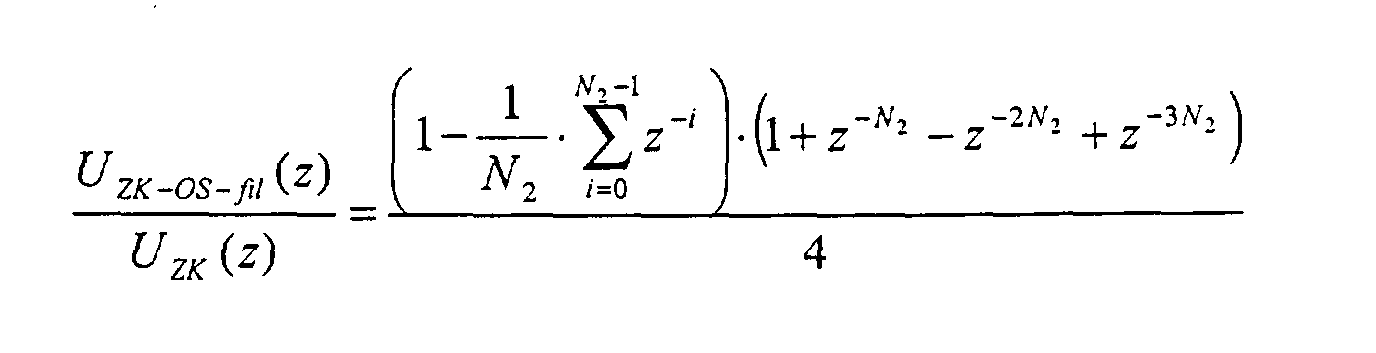
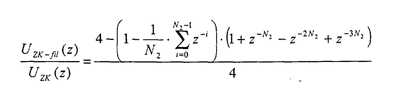
Diese erfindungsgemässe Einrichtung und das erfindungsgemässe Verfahren bringen für alle relevanten Oberschwingungen, insbesondere die vierte Harmonische und mit niedrigerer Priorität die zweite, sechste und achte Harmonische gute Ergebnisse.This device according to the invention and the method according to the invention bring for all relevant harmonics, especially the fourth harmonic and the lower, second, sixth and eighth harmonics good results.
Im folgenden nun genauer auf die wichtigsten Regelungsaspekte der erfindungsgemässen Einrichtung sowie des erfindungsgemässen Verfahrens zur netzseitigen Regelung einer Zwischenkreisspannung eingegangen. Dazu werden Situationen an einem "schwachen" Netz mit starken Netzspannungsoberschwingungen betrachtet und anhand dessen der Nutzen der Einrichtung und des Verfahrens zur netzseitigen Regelung einer Zwischenkreisspannung mit Zwischenkreisspannungsfilterung und verschiedenen Netzspannungsaufschaltungen erläutert wird.In the following, we will now examine the most important control aspects of the inventive Device and the inventive method for grid-side control of a DC link voltage. To do this Situations in a "weak" network with strong mains voltage harmonics considered and based on this the benefit of the facility and the method for regulating an intermediate circuit voltage on the network side with DC link voltage filtering and various mains voltage connections is explained.
In Fig. 20 ist eine Regelung mit (rechts) und ohne (links) die erfindungsgemässe
Einrichtung zur netzseitigen Regelung einer Zwischenkreisspannung dargestellt.
Die dargestellte Netzspannung uN(t) enthält starke Oberschwingungen:
UN-3OS = 20% UN-GS UN-9OS = 5,0% UN-GS
UN-5OS = 8,5% UN-GS UN-11OS = 4,5% UN-GS
UN-7OS = 7,5% UN-GS 20 shows a regulation with (right) and without (left) the device according to the invention for regulating an intermediate circuit voltage on the network side. The mains voltage u N (t) shown contains strong harmonics:
U N-3OS = 20% U N-GS U N-9OS = 5.0% U N-GS
U N-5OS = 8.5% U N-GS U N-11OS = 4.5% U N-GS
U N-7OS = 7.5% U N-GS
Die Zwischenkreisspannung UZK enthält in beiden Fällen starke Oberschwingungen. Ohne die erfindungsgemässe Einrichtung zur netzseitigen Regelung einer Zwischenkreisspannung (linke Darstellung in Fig. 20) gehen diese direkt in die Leistungsanforderung PZK der Zwischenkreisspannungsregeleinrichtung ein und werden in den Sollwert des Netzstromes übertragen. Der Netzstrom iN(t) enthält sehr hohe Oberschwingungen.The intermediate circuit voltage U ZK contains strong harmonics in both cases. Without the device according to the invention for regulating an intermediate circuit voltage on the network side (left-hand illustration in FIG. 20), these go directly into the power requirement P ZK of the intermediate circuit voltage regulating device and are transferred to the nominal value of the mains current. The mains current i N (t) contains very high harmonics.
Mit der vorstehend bereits diskutierten dynamischen Filtereinrichtung 9 in der erfindungsgemässen Einrichtung zur netzseitigen Regelung einer Zwischenkreisspannung wird die verzerrte Zwischenkreisspannung UZK (in Fig. 20 rechts) sehr gut in UZK-fil gefiltert. Hierbei ist zu beachten, dass der Filteralgorithmus nur die Oberschwingungen mit geraden Vielfachen der Netzfrequenz ausfiltert und daher kaum an Dynamik bei Lastsprüngen verloren geht, wie aus Fig. 21 ersichtlich. Die Leistungsanforderung PZK des Zwischenkreisspannungsreglers enthält kaum noch Oberschwingungen. Entsprechend wenig Oberschwingungen sind im Netzstrom iN(t) enthalten.With the dynamic filter device 9 already discussed above in the device according to the invention for regulating an intermediate circuit voltage on the network side, the distorted intermediate circuit voltage U ZK (right in FIG. 20) is filtered very well in U ZK-fil . It should be noted here that the filter algorithm only filters out the harmonics with even multiples of the mains frequency and therefore hardly any dynamics are lost in the event of load jumps, as can be seen from FIG. 21. The power requirement P ZK of the DC link voltage regulator hardly contains any harmonics. Correspondingly few harmonics are contained in the mains current i N (t).
Somit ist erkennbar, dass die erfindungsgemässe Einrichtung zur netzseitigen Regelung einer Zwischenkreisspannung unter Verwendung einer erfindungsgemässen dynamischen Filtereinrichtung 9 besonders effektiv ist. Bei verzerrter Netzspannung sind wesentlich weniger Oberschwingungen im Netzstrom enthalten, im Beispiel ca. 10mal weniger Oberschwingungen, wobei die dritte bis elfte Oberschwingung berücksichtigt wurde.It can thus be seen that the device according to the invention for the network side Regulation of an intermediate circuit voltage using one according to the invention dynamic filter device 9 is particularly effective. With distorted Mains voltage contains significantly fewer harmonics in the mains current, in the example approx. 10 times fewer harmonics, the third to eleventh harmonic was taken into account.
Auch das dynamische Verhalten der erfindungsgemässen Einrichtung sowie des erfindungsgemässen Verfahrens ist, wie vorstehend bereits unter Bezugnahme auf Fig. 21 erwähnt, sehr gut. In Fig. 21 ist die Dynamik am Beispiel eines Lastsprungs bei verzerrter Netzspannung dargestellt. Durch die erfindungsgemässe Einrichtung sowie das erfindungsgemässe Verfahren geht somit praktisch keine Dynamik in der Regelung der Zwischenkreisspannung UZK verloren.As already mentioned above with reference to FIG. 21, the dynamic behavior of the device according to the invention and of the method according to the invention is also very good. 21 shows the dynamics using the example of a load jump with distorted mains voltage. The device according to the invention and the method according to the invention thus practically no dynamics are lost in the regulation of the intermediate circuit voltage U ZK .
In Fig. 22 sind weiterhin Signalverläufe einer direkten Netzspannungsvorsteuerung mit und ohne erfindungsgemässe Totzeitkompensation durch die Einrichtung zur Totzeitkompensation 7 dargestellt. Es werden wieder dieselben Netzspannungsverzerrungen wie in Fig. 20 angenommen. Auch die dynamische Filtereinrichtung 9 wurde benutzt.In FIG. 22 there are also signal curves of a direct mains voltage pre-control with and without dead time compensation according to the invention by the device shown for dead time compensation 7. The same mains voltage distortions become again as assumed in Fig. 20. Even the dynamic one Filter device 9 was used.
In Fig. 22 sind die Netzspannung uN(t), die Wechselrichtersummenspannung uWRΣ(t), der Netzstrom iN(t) und das Spektrum des Netzstromes dargestellt. Bei der direkten Netzspannungsaufschaltung ohne Totzeitkompensation, die in Fig. 22 links dargestellt ist, kommt es aufgrund der Totzeit zwischen Messung der Netzspannung uN(t) und Schalthandlung des Wechselrichters zu viel grösseren Netzstromoberschwingungen als mit Totzeitkompensation (in Fig. 22 auf der rechten Seite). Bereits im zeitlichen Verlauf des Netzstromes iN(t) ist mit Totzeitkompensation eine wesentliche Verbesserung gegenüber der direkten Netzspannungsaufschaltung ohne Totzeitkompensation ersichtlich.22 shows the grid voltage u N (t), the inverter total voltage u WRΣ (t), the grid current i N (t) and the spectrum of the grid current. In the case of direct grid voltage connection without dead time compensation, which is shown on the left in Fig. 22, the dead time between measuring the grid voltage u N (t) and switching the inverter leads to much higher harmonic currents than with dead time compensation (in Fig. 22 on the right side) ). Already in the time course of the mains current i N (t) with dead time compensation a significant improvement over the direct mains voltage connection without dead time compensation can be seen.
Im Spektrum des Netzstromes kann eine quantitative Verbesserung um den Faktor 5 festgestellt werden.In the spectrum of the mains current, a quantitative improvement around the Factor 5 can be determined.
Zusammenfassend ist eine Einrichtung und ein Verfahren zur netzseitigen Regelung einer Zwischenkreisspannung, um unerlaubte Netzwirkungen von Harmonischen der Netzspannung auf den Zwischenkreis zu vermindern bzw. zu beseitigen, offenbart. Dazu wird bei der Regelung der Zwischenkreisspannung die netzseitig bezogene Leistung an die motorseitig abgegebene Leistung angepasst. Die erfindungsgemässe Einrichtung weist unter anderem einen Zwischenkreisspannungsregler 1 zur Ermittlung einer Leistungsanforderung, eine Berechnungseinrichtung 2 zur Berechnung eines Wechselrichtersollspannungszeiger und eines Netzstromsollwertzeigers, eine Transformationseinrichtung 3 zur Transformation dieser Zeiger in den Zeitbereich, eine Netzstromregeleinrichtung 4, eine Regelstreckeneinrichtung 5 zur Ermittlung und Regelung eines Netzspannungsgrundschwingungszeigers und einer Netzfrequenz, eine Einrichtung zur Netzspannungsaufschaltung sowie eine dynamische Filtereinrichtung. Die Netzstromregeleinrichtung 4 regelt einen DC-Anteil im Netzstrom aus, indem er durch geeignete Filterung kompensiert wird. Die Einrichtung zur Netzspannungsaufschaltung entlastet die Netzstromregeleinrichtung 4 bei Netzspannungs-Harmonischen, indem Netzspannungsoberschwingungen auf die Wechselrichtersummenspannung aufgeschaltet werden. Die dynamische Filtereinrichtung befindet sich am Eingang der Einrichtung zur netzseitigen Regelung einer Zwischenkreisspannung, filtert die geradzahlige Harmonische der Grundschwingung aus der Zwischenkreisspannung und subtrahiert diese dann vom Istwert der Zwischenkreisspannung.In summary, a device and a method for network-side control an intermediate circuit voltage to prevent unauthorized network effects from Reduce the harmonics of the mains voltage to the DC link or to eliminate revealed. This is done when regulating the DC link voltage the power drawn on the network side to the power output on the motor side customized. The device according to the invention has, among other things DC link voltage regulator 1 for determining a power requirement, a calculation device 2 for calculating an inverter target voltage pointer and a mains current setpoint pointer, a transformation device 3 to transform these pointers into the time domain, a mains current control device 4, a controlled system device 5 for determining and controlling a mains voltage fundamental wave pointer and a mains frequency, one Device for supplying mains voltage and a dynamic filter device. The mains current control device 4 regulates a DC component in the mains current by compensating it with suitable filtering. The facility for Mains voltage connection relieves the mains current control device 4 Mains voltage harmonics by adding mains voltage harmonics the inverter total voltage are applied. The dynamic The filter device is located at the entrance to the device for network-side regulation an intermediate circuit voltage, filters the even harmonic of the Fundamental from the DC link voltage and then subtracts it from the actual value of the DC link voltage.
Claims (13)
einer Einrichtung zur Totzeitkompensation (7) zur Kompensation einer Totzeit zwischen Abtastung der Netzspannung (uN(t)) und einem Schaltvorgang der Wechselrichter (WR1, ..., WRN), wobei ein durch eine Kompensationsermittlungseinrichtung (7a) aus vergangenen Netzperioden ermittelter Schätzwert (Δukomp(t)) zur Netzspannung (uN(t)) addiert wird.Device for regulating an intermediate circuit voltage on the network side according to claim 1, further comprising
a device for dead time compensation (7) for compensating for a dead time between scanning the grid voltage (u N (t)) and a switching operation of the inverters (WR 1 , ..., WR N ), with a by a compensation determination device (7a) from past grid periods the estimated value (Δu comp (t)) is added to the mains voltage (u N (t)).
die Einrichtung zur Totzeitkompensation (7) weiterhin eine Filtereinrichtung (8) aufweist, die von der Kompensationsermittlungseinrichtung (7a) ausgegebene Schätzwerte (Δukomp(t)) über mehrere Netzperioden speichert und daraus einen fliessenden Mittelwert (Δuk-fil) über mehrere Netzperioden bildet und zur Addition zur Netzspannung (uN(t)) ausgibt.Device for the network-side control of an intermediate circuit voltage according to claim 2, wherein
the device for dead time compensation (7) furthermore has a filter device (8) which stores estimated values (Δu comp (t)) output by the compensation determination device (7a) over a number of network periods and forms a flowing mean value (Δu k-fil ) over a number of network periods and outputs for addition to the mains voltage (u N (t)).
die Einrichtung zur Totzeitkompensation (7) an ihrem Eingang eine Tiefpassfiltereinrichtung zur Filterung hoher Frequenzen ab einigen kHz aufweist.Device for the network-side regulation of an intermediate circuit voltage according to claim 2 or 3, wherein
the device for dead time compensation (7) has at its input a low pass filter device for filtering high frequencies from a few kHz.
einer dynamischen Filtereinrichtung (9) zur Bestimmung von Oberschwingungen der Zwischenkreisspannung (UZK), Filterung der Oberschwingungen (UZK-OS, UZK-OS-fil; u2sin2ωt, ..., u2nsin2nωt) und Subtraktion der Oberschwingungen ((UZK-OS, UZK-OS-fil; u2sin2ωt, ..., u2nsin2nωt) von der Zwischenkreisspannung (UZK) zur Ermittlung einer gefilterten Zwischenkreisspannung (UZK-fil) ohne Oberschwingungen. Device for regulating an intermediate circuit voltage on the network side according to one of Claims 1 to 4, furthermore with
a dynamic filter device (9) for determining harmonics of the intermediate circuit voltage (U ZK ), filtering the harmonics (U ZK-OS , U ZK-OS-fil ; u 2 sin2ωt, ..., u 2n sin2nωt) and subtracting the harmonics ( (U ZK-OS , U ZK-OS-fil ; u 2 sin2ωt, ..., u 2n sin2nωt) from the DC link voltage (U ZK ) to determine a filtered DC link voltage (U ZK-fil ) without harmonics.
die dynamische Filtereinrichtung (9) eine DFT-Filtereinrichtung (10a) zur separaten Transformation aller Oberschwingungen in den Frequenzbereich und zur Ausgabe von Oberschwingungszeigern (U2, ..., U2n) und eine IFT-Filtereinrichtung 10b zur Rücktransformation in den Zeitbereich umfasst, die die Oberschwingungen (u2sin2ωt, ..., u2nsin2ωt) ausgibt.Device for the network-side control of an intermediate circuit voltage according to claim 5, wherein
the dynamic filter device (9) comprises a DFT filter device (10a) for the separate transformation of all harmonics in the frequency range and for the output of harmonic pointers (U 2 , ..., U 2n ) and an IFT filter device 10b for the reverse transformation in the time domain, which outputs the harmonics (u 2 sin2ωt, ..., u 2n sin2ωt).
die dynamische Filtereinrichtung (9) einen Mittelwertbildner (11a) zur Bildung eines fliessenden Mittelwerts und damit zum Herausfiltern aller geraden Oberschwingungen ab der zweiten Oberschwingung und eine Filtereinrichtung (11b) zur Bildung eines fliessenden Mittelwerts über Nfil Werte, wobei jeweils ein Wert pro halber Netzperiode und an entsprechenden Stellen anderer Halbperioden gebildet wird, die die Oberschwingungen (UZK-OS-fil) ausgibt, umfasst.Device for the network-side control of an intermediate circuit voltage according to claim 5, wherein
the dynamic filter device (9) a mean value generator (11a) for forming a flowing mean value and thus for filtering out all even harmonics from the second harmonic and a filter device (11b) for forming a flowing mean value over N fil values, one value per half network period and is formed at corresponding points in other half-periods, which outputs the harmonics (U ZK-OS-fil ).
Kompensieren einer Totzeit zwischen Abtastung der Netzspannung (uN(t)) und einem Schaltvorgang der Wechselrichter (WR1, ..., WRN), indem ein durch eine Kompensationsermittlungseinrichtung (7a) aus vergangenen Netzperioden ermittelter Schätzwert (Δukomp(t)) zur Netzspannung (uN(t)) addiert wird.Method for regulating an intermediate circuit voltage on the network side according to Claim 8, with the further step
Compensating a dead time between sampling the grid voltage (u N (t)) and a switching process of the inverters (WR 1 , ..., WR N ) by an estimate (Δu comp (t) determined by a compensation determination device (7a) from past grid periods ) to the mains voltage (u N (t)) is added.
in dem Schritt des Kompensieren ausgegebene Schätzwerte (Δukomp(t)) über mehrere Netzperioden gespeichert werden und daraus ein fliessender Mittelwert (Δuk-fil) über mehrere Netzperioden gebildet wird und zur Netzspannung (uN(t)) addiert wird.A method for the network-side control of an intermediate circuit voltage according to claim 9, wherein
In the step of compensating, estimated values (Δu comp (t)) are stored over several network periods and a flowing mean value (Δu k-fil ) over several network periods is formed and added to the network voltage (u N (t)).
Ermitteln einer gefilterten Zwischenkreisspannung (UZK-fil) ohne Oberschwingungen durch Bestimmen von Oberschwingungen der Zwischenkreisspannung (UZK), Filtern der Oberschwingungen (UZK-OS, UZK-OS-fil; u2sin2ωt, ..., u2nsin2nωt) und Subtrahieren der Oberschwingungen ((UZK-OS, UZK-OS-fil; u2sin2ωt, ..., u2nsin2nωt) von der Zwischenkreisspannung (UZK).Method for regulating an intermediate circuit voltage on the network side according to one of Claims 8 to 10, with the further steps
Determine a filtered DC link voltage (U ZK-fil ) without harmonics by determining harmonics of the DC link voltage (U ZK ), filtering the harmonics (U ZK-OS , U ZK-OS-fil ; u 2 sin2ωt, ..., u 2n sin2nωt ) and subtracting the harmonics ((U ZK-OS , U ZK-OS-fil ; u 2 sin2ωt, ..., u 2n sin2nωt) from the DC link voltage (U ZK ).
im Schritt des Ermitteln einer gefilterten Zwischenkreisspannung (UZK-fil) alle Oberschwingungen mittels einer DFT separat in den Frequenzbereich transformiert und Oberschwingungszeiger (U2, ..., U2n) ermittelt und mittels einer IFT in den Zeitbereich rücktransformiert und als Oberschwingungen (u2sin2ωt, ..., u2nsin2ωt) ausgeben werden.A method for the network-side control of an intermediate circuit voltage according to claim 11, wherein
in the step of determining a filtered intermediate circuit voltage (U ZK-fil ), all harmonics are separately transformed into the frequency range by means of a DFT and harmonic pointers (U 2 , ..., U 2n ) are determined and transformed back into the time range by means of an IFT and as harmonics (u 2 sin2ωt, ..., u 2n sin2ωt) are output.
im Schritt des Ermittelns einer gefilterten Zwischenkreisspannung (UZK-fil) ein fliessenden Mittelwert der Zwischenkreisspannung (UZK) gebildet wird, alle geraden Oberschwingungen ab der zweiten Oberschwingung herausgefiltert werden und ein fliessender Mittelwerts über Nfil Werte gebildet wird, wobei jeweils ein Wert pro halber Netzperiode und an entsprechenden Stellen anderer Halbperioden gebildet wird, und die Oberschwingungen (UZK-OS-fil) ausgeben werden.A method for the network-side control of an intermediate circuit voltage according to claim 11, wherein
in the step of determining a filtered intermediate circuit voltage (U ZK-fil ), a flowing mean value of the intermediate circuit voltage (U ZK ) is formed, all even harmonics are filtered out from the second harmonic and a flowing mean value over N fil values is formed, one value per half of the network period and at corresponding points in other half periods, and the harmonics (U ZK-OS-fil ) are output.
Applications Claiming Priority (2)
| Application Number | Priority Date | Filing Date | Title |
|---|---|---|---|
| DE10050947 | 2000-10-13 | ||
| DE10050947A DE10050947A1 (en) | 2000-10-13 | 2000-10-13 | Device for regulating intermediate circuit voltage on mains side, e.g. for electric locomotive, has device for determining mains voltage harmonics to be added to correction value for converter desired voltage value |
Publications (3)
| Publication Number | Publication Date |
|---|---|
| EP1204197A2 true EP1204197A2 (en) | 2002-05-08 |
| EP1204197A3 EP1204197A3 (en) | 2004-04-07 |
| EP1204197B1 EP1204197B1 (en) | 2009-03-25 |
Family
ID=7659778
Family Applications (1)
| Application Number | Title | Priority Date | Filing Date |
|---|---|---|---|
| EP01124103A Expired - Lifetime EP1204197B1 (en) | 2000-10-13 | 2001-10-10 | Decive and method for network-side intermediate voltage regulation |
Country Status (5)
| Country | Link |
|---|---|
| EP (1) | EP1204197B1 (en) |
| AT (1) | ATE426938T1 (en) |
| DE (2) | DE10050947A1 (en) |
| DK (1) | DK1204197T3 (en) |
| ES (1) | ES2322230T3 (en) |
Cited By (2)
| Publication number | Priority date | Publication date | Assignee | Title |
|---|---|---|---|---|
| CN105116195A (en) * | 2015-07-13 | 2015-12-02 | 中国人民解放军海军工程大学 | Voltage drop detection method suitable for power grid voltage large harmonic content |
| WO2018024638A1 (en) * | 2016-08-05 | 2018-02-08 | Robert Bosch Gmbh | Method for operating a mains-operated charging device on a non-sinusoidal mains voltage |
Families Citing this family (1)
| Publication number | Priority date | Publication date | Assignee | Title |
|---|---|---|---|---|
| GB2405754A (en) * | 2003-09-03 | 2005-03-09 | Bombardier Transp Gmbh | Converter input detection signal filtering |
Citations (8)
| Publication number | Priority date | Publication date | Assignee | Title |
|---|---|---|---|---|
| US4663702A (en) * | 1984-10-12 | 1987-05-05 | Kabushiki Kaisha Toshiba | Power converter apparatus and control method thereof |
| US4729082A (en) * | 1985-11-21 | 1988-03-01 | Kabushiki Kaisha Toshiba | Control device for power converter |
| DE3824202A1 (en) * | 1988-07-16 | 1990-01-18 | Asea Brown Boveri | Method for controlling a four-quadrant controller |
| DE4037531A1 (en) * | 1990-11-26 | 1992-02-06 | Asea Brown Boveri | Controlling rectifiers in AC inverter for locomotive traction - forming AC rated value by multiplying regulating signal with sinusoidal signal at frequency of AC actual value |
| EP0488201A1 (en) * | 1990-11-28 | 1992-06-03 | Hitachi, Ltd. | Large capacity variable speed driving system for AC electric motor |
| US5373223A (en) * | 1989-07-27 | 1994-12-13 | Seiko Epson Corporation | Power converter/inverter system with instantaneous real power feedback control |
| JPH07213067A (en) * | 1994-01-24 | 1995-08-11 | Fuji Electric Co Ltd | PWM converter control circuit |
| DE19711534A1 (en) * | 1997-03-20 | 1998-10-01 | Abb Daimler Benz Transp | Method for regulating the continuous voltage of a current rectifier |
Family Cites Families (1)
| Publication number | Priority date | Publication date | Assignee | Title |
|---|---|---|---|---|
| DE19542163A1 (en) * | 1995-11-11 | 1997-01-16 | Abb Daimler Benz Transp | Control of rectifier output voltage e.g. for electrical supply of electric vehicles - has gate voltage taken from regulator which uses discrepancy in rectifier output voltage and reactive input current as parameters |
-
2000
- 2000-10-13 DE DE10050947A patent/DE10050947A1/en not_active Ceased
-
2001
- 2001-10-10 DE DE50114785T patent/DE50114785D1/en not_active Expired - Lifetime
- 2001-10-10 EP EP01124103A patent/EP1204197B1/en not_active Expired - Lifetime
- 2001-10-10 ES ES01124103T patent/ES2322230T3/en not_active Expired - Lifetime
- 2001-10-10 AT AT01124103T patent/ATE426938T1/en active
- 2001-10-10 DK DK01124103T patent/DK1204197T3/en active
Patent Citations (8)
| Publication number | Priority date | Publication date | Assignee | Title |
|---|---|---|---|---|
| US4663702A (en) * | 1984-10-12 | 1987-05-05 | Kabushiki Kaisha Toshiba | Power converter apparatus and control method thereof |
| US4729082A (en) * | 1985-11-21 | 1988-03-01 | Kabushiki Kaisha Toshiba | Control device for power converter |
| DE3824202A1 (en) * | 1988-07-16 | 1990-01-18 | Asea Brown Boveri | Method for controlling a four-quadrant controller |
| US5373223A (en) * | 1989-07-27 | 1994-12-13 | Seiko Epson Corporation | Power converter/inverter system with instantaneous real power feedback control |
| DE4037531A1 (en) * | 1990-11-26 | 1992-02-06 | Asea Brown Boveri | Controlling rectifiers in AC inverter for locomotive traction - forming AC rated value by multiplying regulating signal with sinusoidal signal at frequency of AC actual value |
| EP0488201A1 (en) * | 1990-11-28 | 1992-06-03 | Hitachi, Ltd. | Large capacity variable speed driving system for AC electric motor |
| JPH07213067A (en) * | 1994-01-24 | 1995-08-11 | Fuji Electric Co Ltd | PWM converter control circuit |
| DE19711534A1 (en) * | 1997-03-20 | 1998-10-01 | Abb Daimler Benz Transp | Method for regulating the continuous voltage of a current rectifier |
Non-Patent Citations (1)
| Title |
|---|
| PATENT ABSTRACTS OF JAPAN vol. 1995, no. 11, 26. Dezember 1995 (1995-12-26) -& JP 07 213067 A (FUJI ELECTRIC CO LTD), 11. August 1995 (1995-08-11) * |
Cited By (3)
| Publication number | Priority date | Publication date | Assignee | Title |
|---|---|---|---|---|
| CN105116195A (en) * | 2015-07-13 | 2015-12-02 | 中国人民解放军海军工程大学 | Voltage drop detection method suitable for power grid voltage large harmonic content |
| CN105116195B (en) * | 2015-07-13 | 2018-07-06 | 中国人民解放军海军工程大学 | A voltage drop detection method suitable for grid voltage with large harmonic content |
| WO2018024638A1 (en) * | 2016-08-05 | 2018-02-08 | Robert Bosch Gmbh | Method for operating a mains-operated charging device on a non-sinusoidal mains voltage |
Also Published As
| Publication number | Publication date |
|---|---|
| DK1204197T3 (en) | 2009-07-13 |
| DE10050947A1 (en) | 2002-04-25 |
| ES2322230T3 (en) | 2009-06-18 |
| EP1204197A3 (en) | 2004-04-07 |
| DE50114785D1 (en) | 2009-05-07 |
| EP1204197B1 (en) | 2009-03-25 |
| ATE426938T1 (en) | 2009-04-15 |
Similar Documents
| Publication | Publication Date | Title |
|---|---|---|
| DE3751020T2 (en) | Device for the suppression of harmonics. | |
| DE69318247T2 (en) | System and method for controlling a pulse width modulated inverter | |
| EP1258978B1 (en) | Current supply system | |
| WO1999067868A2 (en) | Hybrid filter for an alternating current network | |
| EP0800265B1 (en) | Process and apparatus for direct torque control of an induction machine | |
| WO2001020745A1 (en) | Method for controlling the reactive power and device for generating electrical energy in an electrical network | |
| DE69011312T2 (en) | Inverter control device. | |
| WO1996009685A1 (en) | Process for regulating a four-quadrant regulator operating as a mains converter | |
| DE3429116C2 (en) | ||
| EP1204197A2 (en) | Decive and method for network-side intermediate voltage regulation | |
| EP3876406A1 (en) | Method and device for compensating for leakage current in an emi-filter | |
| DE3721631C2 (en) | ||
| EP0782783B1 (en) | Process for regulating a four-quadrant regulator that works as mains power converter | |
| EP0663713B1 (en) | Method for adaptive compensation of effects of a non linear load and device therefore | |
| DE19734722C2 (en) | Method and device for improving the power quality of a superimposed network | |
| DE2627537C2 (en) | Circuit arrangement for regulating the motor current in a three-phase three-phase motor fed by a converter | |
| DE69820262T2 (en) | METHOD AND DEVICE FOR CONTROLLING THE SWITCHES IN A CONTROL SYSTEM WITH A VARIABLE STRUCTURE AND CONTROLLABLE FREQUENCY | |
| DE10244056B3 (en) | Method for generating a set of control signals for a converter of an active filter to compensate for harmonics and other vibrations and device for carrying them out | |
| WO2021116166A1 (en) | Method for identifying the filter inductor of a grid inverter | |
| DE4314056C2 (en) | Circuit arrangement for producing a harmonic-free voltage from the vehicle electrical system voltage of motor vehicles | |
| EP1017157B1 (en) | Method for the control of a non-harmonic network current portion of a converter, and device for carrying out the method | |
| DE102021130424B4 (en) | Method and system for compensating a network impedance in a vehicle charging system | |
| DE19949997A1 (en) | Characteristic value determination method for sinusoidal current or voltage signal, involves integrating electrical signal using coupled integrators such that output signal has suitable phase shift | |
| DE102023106050A1 (en) | METHOD AND CONTROL UNIT FOR REDUCING HARMONIC POWER FLOWS AND SUB-NETWORK WITH CONTROL UNIT | |
| DE112004001647B4 (en) | Transmission of electrical power from a primary side to a secondary side of a converter |
Legal Events
| Date | Code | Title | Description |
|---|---|---|---|
| PUAI | Public reference made under article 153(3) epc to a published international application that has entered the european phase |
Free format text: ORIGINAL CODE: 0009012 |
|
| AK | Designated contracting states |
Kind code of ref document: A2 Designated state(s): AT BE CH CY DE DK ES FI FR GB GR IE IT LI LU MC NL PT SE TR |
|
| AX | Request for extension of the european patent |
Free format text: AL;LT;LV;MK;RO;SI |
|
| PUAL | Search report despatched |
Free format text: ORIGINAL CODE: 0009013 |
|
| AK | Designated contracting states |
Kind code of ref document: A3 Designated state(s): AT BE CH CY DE DK ES FI FR GB GR IE IT LI LU MC NL PT SE TR |
|
| AX | Request for extension of the european patent |
Extension state: AL LT LV MK RO SI |
|
| RIC1 | Information provided on ipc code assigned before grant |
Ipc: 7H 02M 7/12 A Ipc: 7H 02M 1/12 B |
|
| 17P | Request for examination filed |
Effective date: 20040430 |
|
| AKX | Designation fees paid |
Designated state(s): AT BE CH CY DE DK ES FI FR GB GR IE IT LI LU MC NL PT SE TR |
|
| RAP1 | Party data changed (applicant data changed or rights of an application transferred) |
Owner name: BOMBARDIER TRANSPORTATION GMBH |
|
| GRAP | Despatch of communication of intention to grant a patent |
Free format text: ORIGINAL CODE: EPIDOSNIGR1 |
|
| GRAS | Grant fee paid |
Free format text: ORIGINAL CODE: EPIDOSNIGR3 |
|
| GRAA | (expected) grant |
Free format text: ORIGINAL CODE: 0009210 |
|
| AK | Designated contracting states |
Kind code of ref document: B1 Designated state(s): AT BE CH CY DE DK ES FI FR GB GR IE IT LI LU MC NL PT SE TR |
|
| REG | Reference to a national code |
Ref country code: GB Ref legal event code: FG4D Free format text: NOT ENGLISH |
|
| REG | Reference to a national code |
Ref country code: CH Ref legal event code: EP |
|
| REG | Reference to a national code |
Ref country code: IE Ref legal event code: FG4D Free format text: LANGUAGE OF EP DOCUMENT: GERMAN |
|
| REG | Reference to a national code |
Ref country code: CH Ref legal event code: NV Representative=s name: TROESCH SCHEIDEGGER WERNER AG |
|
| REF | Corresponds to: |
Ref document number: 50114785 Country of ref document: DE Date of ref document: 20090507 Kind code of ref document: P |
|
| REG | Reference to a national code |
Ref country code: ES Ref legal event code: FG2A Ref document number: 2322230 Country of ref document: ES Kind code of ref document: T3 |
|
| REG | Reference to a national code |
Ref country code: DK Ref legal event code: T3 |
|
| REG | Reference to a national code |
Ref country code: SE Ref legal event code: TRGR |
|
| NLV1 | Nl: lapsed or annulled due to failure to fulfill the requirements of art. 29p and 29m of the patents act | ||
| REG | Reference to a national code |
Ref country code: IE Ref legal event code: FD4D |
|
| PG25 | Lapsed in a contracting state [announced via postgrant information from national office to epo] |
Ref country code: PT Free format text: LAPSE BECAUSE OF FAILURE TO SUBMIT A TRANSLATION OF THE DESCRIPTION OR TO PAY THE FEE WITHIN THE PRESCRIBED TIME-LIMIT Effective date: 20090831 |
|
| PG25 | Lapsed in a contracting state [announced via postgrant information from national office to epo] |
Ref country code: NL Free format text: LAPSE BECAUSE OF FAILURE TO SUBMIT A TRANSLATION OF THE DESCRIPTION OR TO PAY THE FEE WITHIN THE PRESCRIBED TIME-LIMIT Effective date: 20090325 |
|
| PG25 | Lapsed in a contracting state [announced via postgrant information from national office to epo] |
Ref country code: IE Free format text: LAPSE BECAUSE OF FAILURE TO SUBMIT A TRANSLATION OF THE DESCRIPTION OR TO PAY THE FEE WITHIN THE PRESCRIBED TIME-LIMIT Effective date: 20090325 |
|
| PLBE | No opposition filed within time limit |
Free format text: ORIGINAL CODE: 0009261 |
|
| STAA | Information on the status of an ep patent application or granted ep patent |
Free format text: STATUS: NO OPPOSITION FILED WITHIN TIME LIMIT |
|
| 26N | No opposition filed |
Effective date: 20091229 |
|
| BERE | Be: lapsed |
Owner name: BOMBARDIER TRANSPORTATION G.M.B.H. Effective date: 20091031 |
|
| PG25 | Lapsed in a contracting state [announced via postgrant information from national office to epo] |
Ref country code: MC Free format text: LAPSE BECAUSE OF NON-PAYMENT OF DUE FEES Effective date: 20091031 |
|
| PG25 | Lapsed in a contracting state [announced via postgrant information from national office to epo] |
Ref country code: GR Free format text: LAPSE BECAUSE OF FAILURE TO SUBMIT A TRANSLATION OF THE DESCRIPTION OR TO PAY THE FEE WITHIN THE PRESCRIBED TIME-LIMIT Effective date: 20090626 Ref country code: BE Free format text: LAPSE BECAUSE OF NON-PAYMENT OF DUE FEES Effective date: 20091031 |
|
| PG25 | Lapsed in a contracting state [announced via postgrant information from national office to epo] |
Ref country code: GB Free format text: LAPSE BECAUSE OF NON-PAYMENT OF DUE FEES Effective date: 20091010 |
|
| PG25 | Lapsed in a contracting state [announced via postgrant information from national office to epo] |
Ref country code: IT Free format text: LAPSE BECAUSE OF FAILURE TO SUBMIT A TRANSLATION OF THE DESCRIPTION OR TO PAY THE FEE WITHIN THE PRESCRIBED TIME-LIMIT Effective date: 20090325 |
|
| PG25 | Lapsed in a contracting state [announced via postgrant information from national office to epo] |
Ref country code: LU Free format text: LAPSE BECAUSE OF NON-PAYMENT OF DUE FEES Effective date: 20091010 |
|
| PG25 | Lapsed in a contracting state [announced via postgrant information from national office to epo] |
Ref country code: TR Free format text: LAPSE BECAUSE OF FAILURE TO SUBMIT A TRANSLATION OF THE DESCRIPTION OR TO PAY THE FEE WITHIN THE PRESCRIBED TIME-LIMIT Effective date: 20090325 |
|
| PG25 | Lapsed in a contracting state [announced via postgrant information from national office to epo] |
Ref country code: CY Free format text: LAPSE BECAUSE OF FAILURE TO SUBMIT A TRANSLATION OF THE DESCRIPTION OR TO PAY THE FEE WITHIN THE PRESCRIBED TIME-LIMIT Effective date: 20090325 |
|
| REG | Reference to a national code |
Ref country code: FR Ref legal event code: PLFP Year of fee payment: 15 |
|
| PGFP | Annual fee paid to national office [announced via postgrant information from national office to epo] |
Ref country code: DK Payment date: 20151021 Year of fee payment: 15 |
|
| PGFP | Annual fee paid to national office [announced via postgrant information from national office to epo] |
Ref country code: ES Payment date: 20151021 Year of fee payment: 15 |
|
| REG | Reference to a national code |
Ref country code: FR Ref legal event code: PLFP Year of fee payment: 16 |
|
| REG | Reference to a national code |
Ref country code: DK Ref legal event code: EBP Effective date: 20161031 |
|
| REG | Reference to a national code |
Ref country code: FR Ref legal event code: PLFP Year of fee payment: 17 |
|
| PG25 | Lapsed in a contracting state [announced via postgrant information from national office to epo] |
Ref country code: DK Free format text: LAPSE BECAUSE OF NON-PAYMENT OF DUE FEES Effective date: 20161031 |
|
| PG25 | Lapsed in a contracting state [announced via postgrant information from national office to epo] |
Ref country code: ES Free format text: LAPSE BECAUSE OF FAILURE TO SUBMIT A TRANSLATION OF THE DESCRIPTION OR TO PAY THE FEE WITHIN THE PRESCRIBED TIME-LIMIT Effective date: 20090325 |
|
| REG | Reference to a national code |
Ref country code: FR Ref legal event code: PLFP Year of fee payment: 18 |
|
| REG | Reference to a national code |
Ref country code: ES Ref legal event code: FD2A Effective date: 20181121 |
|
| PGFP | Annual fee paid to national office [announced via postgrant information from national office to epo] |
Ref country code: SE Payment date: 20181019 Year of fee payment: 18 Ref country code: DE Payment date: 20181019 Year of fee payment: 18 Ref country code: FI Payment date: 20181022 Year of fee payment: 18 Ref country code: AT Payment date: 20181022 Year of fee payment: 18 |
|
| PG25 | Lapsed in a contracting state [announced via postgrant information from national office to epo] |
Ref country code: ES Free format text: LAPSE BECAUSE OF FAILURE TO SUBMIT A TRANSLATION OF THE DESCRIPTION OR TO PAY THE FEE WITHIN THE PRESCRIBED TIME-LIMIT Effective date: 20161011 |
|
| PGFP | Annual fee paid to national office [announced via postgrant information from national office to epo] |
Ref country code: CH Payment date: 20181019 Year of fee payment: 18 Ref country code: FR Payment date: 20181022 Year of fee payment: 18 |
|
| REG | Reference to a national code |
Ref country code: DE Ref legal event code: R119 Ref document number: 50114785 Country of ref document: DE |
|
| REG | Reference to a national code |
Ref country code: FI Ref legal event code: MAE |
|
| REG | Reference to a national code |
Ref country code: CH Ref legal event code: PL |
|
| PG25 | Lapsed in a contracting state [announced via postgrant information from national office to epo] |
Ref country code: CH Free format text: LAPSE BECAUSE OF NON-PAYMENT OF DUE FEES Effective date: 20191031 Ref country code: FI Free format text: LAPSE BECAUSE OF NON-PAYMENT OF DUE FEES Effective date: 20191010 Ref country code: DE Free format text: LAPSE BECAUSE OF NON-PAYMENT OF DUE FEES Effective date: 20200501 Ref country code: LI Free format text: LAPSE BECAUSE OF NON-PAYMENT OF DUE FEES Effective date: 20191031 |
|
| REG | Reference to a national code |
Ref country code: AT Ref legal event code: MM01 Ref document number: 426938 Country of ref document: AT Kind code of ref document: T Effective date: 20191010 |
|
| PG25 | Lapsed in a contracting state [announced via postgrant information from national office to epo] |
Ref country code: SE Free format text: LAPSE BECAUSE OF NON-PAYMENT OF DUE FEES Effective date: 20191011 |
|
| PG25 | Lapsed in a contracting state [announced via postgrant information from national office to epo] |
Ref country code: FR Free format text: LAPSE BECAUSE OF NON-PAYMENT OF DUE FEES Effective date: 20191031 |
|
| PG25 | Lapsed in a contracting state [announced via postgrant information from national office to epo] |
Ref country code: AT Free format text: LAPSE BECAUSE OF NON-PAYMENT OF DUE FEES Effective date: 20191010 |