EP0488201A1 - Large capacity variable speed driving system for AC electric motor - Google Patents
Large capacity variable speed driving system for AC electric motor Download PDFInfo
- Publication number
- EP0488201A1 EP0488201A1 EP91120256A EP91120256A EP0488201A1 EP 0488201 A1 EP0488201 A1 EP 0488201A1 EP 91120256 A EP91120256 A EP 91120256A EP 91120256 A EP91120256 A EP 91120256A EP 0488201 A1 EP0488201 A1 EP 0488201A1
- Authority
- EP
- European Patent Office
- Prior art keywords
- inverter
- large capacity
- variable speed
- motor
- power
- Prior art date
- Legal status (The legal status is an assumption and is not a legal conclusion. Google has not performed a legal analysis and makes no representation as to the accuracy of the status listed.)
- Granted
Links
Images


Classifications
-
- H—ELECTRICITY
- H03—ELECTRONIC CIRCUITRY
- H03K—PULSE TECHNIQUE
- H03K17/00—Electronic switching or gating, i.e. not by contact-making and –breaking
- H03K17/08—Modifications for protecting switching circuit against overcurrent or overvoltage
- H03K17/081—Modifications for protecting switching circuit against overcurrent or overvoltage without feedback from the output circuit to the control circuit
- H03K17/0814—Modifications for protecting switching circuit against overcurrent or overvoltage without feedback from the output circuit to the control circuit by measures taken in the output circuit
- H03K17/08144—Modifications for protecting switching circuit against overcurrent or overvoltage without feedback from the output circuit to the control circuit by measures taken in the output circuit in thyristor switches
-
- H—ELECTRICITY
- H02—GENERATION; CONVERSION OR DISTRIBUTION OF ELECTRIC POWER
- H02M—APPARATUS FOR CONVERSION BETWEEN AC AND AC, BETWEEN AC AND DC, OR BETWEEN DC AND DC, AND FOR USE WITH MAINS OR SIMILAR POWER SUPPLY SYSTEMS; CONVERSION OF DC OR AC INPUT POWER INTO SURGE OUTPUT POWER; CONTROL OR REGULATION THEREOF
- H02M5/00—Conversion of ac power input into ac power output, e.g. for change of voltage, for change of frequency, for change of number of phases
- H02M5/40—Conversion of ac power input into ac power output, e.g. for change of voltage, for change of frequency, for change of number of phases with intermediate conversion into dc
- H02M5/42—Conversion of ac power input into ac power output, e.g. for change of voltage, for change of frequency, for change of number of phases with intermediate conversion into dc by static converters
- H02M5/44—Conversion of ac power input into ac power output, e.g. for change of voltage, for change of frequency, for change of number of phases with intermediate conversion into dc by static converters using discharge tubes or semiconductor devices to convert the intermediate dc into ac
- H02M5/443—Conversion of ac power input into ac power output, e.g. for change of voltage, for change of frequency, for change of number of phases with intermediate conversion into dc by static converters using discharge tubes or semiconductor devices to convert the intermediate dc into ac using devices of a thyratron or thyristor type requiring extinguishing means
- H02M5/45—Conversion of ac power input into ac power output, e.g. for change of voltage, for change of frequency, for change of number of phases with intermediate conversion into dc by static converters using discharge tubes or semiconductor devices to convert the intermediate dc into ac using devices of a thyratron or thyristor type requiring extinguishing means using semiconductor devices only
- H02M5/4505—Conversion of ac power input into ac power output, e.g. for change of voltage, for change of frequency, for change of number of phases with intermediate conversion into dc by static converters using discharge tubes or semiconductor devices to convert the intermediate dc into ac using devices of a thyratron or thyristor type requiring extinguishing means using semiconductor devices only having a rectifier with controlled elements
-
- H—ELECTRICITY
- H02—GENERATION; CONVERSION OR DISTRIBUTION OF ELECTRIC POWER
- H02M—APPARATUS FOR CONVERSION BETWEEN AC AND AC, BETWEEN AC AND DC, OR BETWEEN DC AND DC, AND FOR USE WITH MAINS OR SIMILAR POWER SUPPLY SYSTEMS; CONVERSION OF DC OR AC INPUT POWER INTO SURGE OUTPUT POWER; CONTROL OR REGULATION THEREOF
- H02M7/00—Conversion of ac power input into dc power output; Conversion of dc power input into ac power output
- H02M7/42—Conversion of dc power input into ac power output without possibility of reversal
- H02M7/44—Conversion of dc power input into ac power output without possibility of reversal by static converters
- H02M7/48—Conversion of dc power input into ac power output without possibility of reversal by static converters using discharge tubes with control electrode or semiconductor devices with control electrode
- H02M7/505—Conversion of dc power input into ac power output without possibility of reversal by static converters using discharge tubes with control electrode or semiconductor devices with control electrode using devices of a thyratron or thyristor type requiring extinguishing means
- H02M7/515—Conversion of dc power input into ac power output without possibility of reversal by static converters using discharge tubes with control electrode or semiconductor devices with control electrode using devices of a thyratron or thyristor type requiring extinguishing means using semiconductor devices only
- H02M7/525—Conversion of dc power input into ac power output without possibility of reversal by static converters using discharge tubes with control electrode or semiconductor devices with control electrode using devices of a thyratron or thyristor type requiring extinguishing means using semiconductor devices only with automatic control of output waveform or frequency
- H02M7/527—Conversion of dc power input into ac power output without possibility of reversal by static converters using discharge tubes with control electrode or semiconductor devices with control electrode using devices of a thyratron or thyristor type requiring extinguishing means using semiconductor devices only with automatic control of output waveform or frequency by pulse width modulation
-
- H—ELECTRICITY
- H02—GENERATION; CONVERSION OR DISTRIBUTION OF ELECTRIC POWER
- H02P—CONTROL OR REGULATION OF ELECTRIC MOTORS, ELECTRIC GENERATORS OR DYNAMO-ELECTRIC CONVERTERS; CONTROLLING TRANSFORMERS, REACTORS OR CHOKE COILS
- H02P21/00—Arrangements or methods for the control of electric machines by vector control, e.g. by control of field orientation
- H02P21/0085—Arrangements or methods for the control of electric machines by vector control, e.g. by control of field orientation specially adapted for high speeds, e.g. above nominal speed
- H02P21/0089—Arrangements or methods for the control of electric machines by vector control, e.g. by control of field orientation specially adapted for high speeds, e.g. above nominal speed using field weakening
-
- H—ELECTRICITY
- H02—GENERATION; CONVERSION OR DISTRIBUTION OF ELECTRIC POWER
- H02P—CONTROL OR REGULATION OF ELECTRIC MOTORS, ELECTRIC GENERATORS OR DYNAMO-ELECTRIC CONVERTERS; CONTROLLING TRANSFORMERS, REACTORS OR CHOKE COILS
- H02P21/00—Arrangements or methods for the control of electric machines by vector control, e.g. by control of field orientation
- H02P21/02—Arrangements or methods for the control of electric machines by vector control, e.g. by control of field orientation specially adapted for optimising the efficiency at low load
-
- H—ELECTRICITY
- H02—GENERATION; CONVERSION OR DISTRIBUTION OF ELECTRIC POWER
- H02P—CONTROL OR REGULATION OF ELECTRIC MOTORS, ELECTRIC GENERATORS OR DYNAMO-ELECTRIC CONVERTERS; CONTROLLING TRANSFORMERS, REACTORS OR CHOKE COILS
- H02P21/00—Arrangements or methods for the control of electric machines by vector control, e.g. by control of field orientation
- H02P21/06—Rotor flux based control involving the use of rotor position or rotor speed sensors
-
- H—ELECTRICITY
- H03—ELECTRONIC CIRCUITRY
- H03K—PULSE TECHNIQUE
- H03K2217/00—Indexing scheme related to electronic switching or gating, i.e. not by contact-making or -breaking covered by H03K17/00
- H03K2217/0081—Power supply means, e.g. to the switch driver
Definitions
- the present invention relates to a variable speed driving system for an AC electric motor, and more particularly to a large capacity variable speed driving system for driving an AC electric motor using a power converter device provided with a GTO (gate turn-off) thyristor.
- GTO gate turn-off
- variable speed driving system for an AC electric motor with the largest capacity using an inverter is a system with 4000 kVA for general industry such as a pump and a fan.
- An example of this system is disclosed in e.g. "Toshiba Review” Vol. 43, No. 3 (1983) page 253.
- a GTO thyristor used as a switching device in a main circuit is a high- voltage large current device. But, with the device capacity increased, the permissible switching frequency of the device is reduced (the present limit is 100 - 150 Hz) so that adoption of the GTO thyristor does not have merits in that harmonics of the output wave from the inverter are increased, the torque ripple of a motor is increased, and loss in the snubber circuit for the GTO is increased (at the rate of square of the voltage).
- the power factor in a power source is limited to around 0. 6.
- a capacitor with a large capacitance for improving the power factor is required on the power source side.
- the resultant apparatus has a large scale.
- An object of the present invention is to provide a large capacity variable speed driving system for an AC electric motor which can provide the torque ripple of 1% or less of the AC electric motor by an inverter having a capacity of 2000 kVA or more provided with GTO thyristors.
- a plurality of inverter units each comprising a GTO thyristor with its permissible switching frequency of 500 Hz or more as switching devices in a main circuit, are connected in parallel in a multiplex manner, and a PWM (pulse width modulation) control device in an instantaneous spatial vector PWM control system or a spatial vector type SH (sub-harmonics) system controls the output from the inverter.
- a PWM pulse width modulation
- the inverter output voltage can be PWM-controlled precisely so that the harmonics of the inverter output current can be reduced thereby to decrease the torque ripple of the motor.
- the PWM control device in the instantaneous spatial vector system or the spatial vector type SH system selects the voltage vector along the magnetic flux circle of the electric motor to control the output voltage from the inverter, the torque ripple of the electric motor can be further reduced. By combining the components mentioned above, the torque ripple of 1% or less in the motor can be attained.
- the present invention is applied to driving a vehicle, because of high efficiency due to reduction of snubber loss, a cooling system can be miniaturized to reduce the weight of the vehicle body. Also, if the present invention is applied to AC driving for general industry. e.g., driving a pump and a fun, because of high efficiency, the effect of reducing energy can be further improved.
- the equivalent switching frequency viewed from a motor side can be changed into a high switching frequency.
- the inverter output voltage can be PWM-controlled precisely so that the harmonics of the inverter output current can be reduced thereby to decrease the torque ripple of the motor.
- the PWM control device in the instantaneous spatial vector system or the spatial vector type SH system selects the voltage vector along the magnetic flux circle of the electric motor to control the output voltage from the inverter, the torque ripple of the electric motor can be further reduced.
- an inverter 100 is composed of inverter units 110 and 120, and a converter 200 is composed of converter units 210 and 220.
- switching devices or elements 111, 121, 211 and 221 are large-capacity high-frequency GTO thyristors rated at the voltage of 4.5 kV, the current of 3 kA and the switching frequency of 500 Hz or more.
- Each inverter unit and each converter unit are connected through capacitors 71 and 72, respectively.
- the output terminals 110 and 120 of the inverter units are connected in parallel in a multiplex manner (hereinafter expressed as multi-connected in parallel or connected in multi-parallel) through an interphase reactor 92, and the middle point of the interphase reactor 92 is connected with an AC electric motor 5.
- the input terminals of the other converter units 210 and 220 are also multi-connected in parallel through another interphase reactor 93, and the middle point of interphase reactor 93 is connected with an AC power source 6.
- the GTO thyristors constituting a main circuit of the above inverter and converter units are connected with a snubber circuit and a snubber energy recovering circuit 4 for recovering the electric energy stored in the snubber circuit to a DC power source on the side of the above capacitors.
- the inverter 100 and the converter 200 are controlled by a control circuit 300.
- the inverter 100 is controlled by a speed/vector control circuit 330 and an instantaneous spatial vector PWM control circuit 310
- the converter 200 is controlled by a power factor adjustment/voltage control circuit 340 and another instantaneous spatial vector PWM control circuit 320.
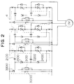
- the snubber energy recovering system 4 is constructed as shown in Fig. 2 for each inverter unit and for converter unit.
- a snubber circuit is composed of a first capacitor 2100, a second capacitor 2200 and two diodes 2300 and 2400 connected in series.
- the anode of the diode 2300 is connected with the positive terminal of a main switching circuit through the first capacitor 2100 and the cathode of the diode 2400 is connected with the negative terminal of the main switching circuit.
- the common junction of the diodes 2300 and 2400 connected in series is connected with a common junction of positive and negative arms through the second capacitor 2200.
- a snubber recovering circuit is composed of a diode 3800, a transformer 3000 and a resistor 3100.
- the primary winding of the transformer 3000 is connected in parallel with the series connection of the diodes 2300 and 2400, and connected in parallel with a DC terminal through the first capacitor 2100 whereas the secondary winding of the transformer 3000 is connected with the DC terminal through the diode 3800 for preventing a current from flowing a reverse direction.
- the resistor 3100 for reset is connected across the primary winding of the transformer 3000 so that part of the discharged current due to the snubber energy is bypassed to recover the snubber energy through the resistor 3100; thus, the excited current of the transformer 3000 is attenuated rapidly to prevent the magnetic saturation of an iron core. In this way, the current which flows continuously even when the snubber recovering energy is not being recovered can be reset rapidly by the resistor 3100 so that the magnetic saturation of the iron core can be prevented and thus the transformer can be miniaturized.
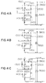
- Figs. 3A to 3F show the circuit operation in which the current flow state of a positive arm is returned to the same state via the current flow state of a negative arm.
- a GTO thyristor is 'on' and an current iL from is supplied to an AC terminal.
- an off-gate signal is applied to the GTO thyristor 1100, the current iL having flowed until now flows along the path (capacitor 2100 - diode 2300 - capacitor 2200) as shown in Fig. 3B.
- a switching surge is absorbed and the energy with the polarity as shown stored in the capacitor 2200 is discharged to the AC terminal.
- Fig. 3A shows the circuit operation in which the current flow state of a positive arm is returned to the same state via the current flow state of a negative arm.
- Figs. 4A to 4F show the circuit operation in which the current flow state of the negative arm is returned to the same state via the current flow state of the positive arm.
- the current commutation operations in Figs. 3A to 3D are commutation operations in the delayed-phase mode as in Figs. 3A to 3C.
- the current commutation operations in Figs. 4D to 4F are the commutation operations in the advanced-phase mode as in Figs. 3C to 3F.
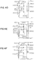
- Fig. 5 shows an arrangement for snubber energy recovering in which a transformer is not provided for each phase unlike Fig. 2 but for all the phases. This arrangement permits the snubber recovering system to be further small-sized.
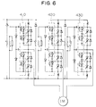
- Figs. 6 and 7 show an arrangement including GTO thyristors connected in series to cause the converter to have a large capacity. It should be noted that a transformer is not provided for each phase but for all the phases.
- 410, 420 and 430 denote snubber circuits each provided with a diode, a capacitor and a resistor. The snubber circuits are individually connected with each GTO thyristor so that the sharing voltage of each of the GTO thyristors connected in series can be equalized.
- a DC/DC converter 3200 may be used in place of the transformer as shown in Figs. 8A and 8B.
- the arm arrangement in Fig. 8B is composed of GTO thyristors connected in series.
- a capacitor 2100 is always charged to a DC voltage Ed; the excessively charged energy from the voltage Ed is recovered to the DC side.
- the energy recovering system described above can provide the energy recovering rate of 80% or more. This is because in the case of using a transformer, the resistor for reset connected in parallel with the transformer has loss of 10 - 20%, and also in the case of using a DC/DC converter, the converter has loss at the same degree.
- Fig. 9 shows the loss and efficiency of a power converter when an induction motor is driven by the power converter in which the converter and inverter are connected in multi-parallel.
- the capacitance of 2700 kVA (1350 kVA x 2) of the power converter concerned the turn on/off switching loss of GTO is reduced to 33 kW; the snubber loss can be reduced to 40 kW by the energy recovering circuit; and the other loss of e.g. an inter-phase reactor is 29 kW.
- the total efficiency of the converter of 96.2% could be attained.
- Fig. 10 shows an arrangement of the speed/vector control circuit 330 included in Fig. 1.
- This arrangement is composed of a speed adjusting device 3302 for generating a torque current command Iq * on the basis of a difference between a speed command ⁇ * and the rotating speed ⁇ of the three-phase electric motor by a speed detector 51, a field weakening control circuit 3301 for generating an excited current command Id * from the rotating speed ⁇ r, a slip calculator 3308 for calculating the slipping frequency ws on the basis of the torque current command and the excited current command, an adder 3309 for adding the slipping frequency and the rotating speed to calculate a first order frequency ⁇ 1 * , a converter 3307 for converting the three-phase AC currents iu - iw detected by a current detector 81 into the currents Id and Iq corresponding to the torque and excited component, a DC current adjusting device 3303 for generating a voltage command Vq * from the difference between the command value Iq * and detected value Iq of
- An instantaneous spatial vector PWM control unit 310 serves to PWM-control the output voltage from the inverter on the basis of the above first order voltage commands.
- the control unit 310 is provided with a circulating current control unit 3101 for suppressing the current circulating through the inverter units.
- the above control arrangement is shown in block form in which the signals are processed in an analog manner, the control/processing in the present invention is actually carried out using a microcomputer.
- the response characteristic of the speed control system depends on the magnitude of the inertia of a load and the response characteristic of the current control system (ACR). It is generally recognized that stabilized speed control can be made if the response of ACR is 5 to 10 times as large as that of ASR.
- the DC ACR for Id and Iq is used so that all the vectors can be processed in DC magnitudes.
- the DC ACR can control the current in a more stabilized manner and with less control error than an AC ACR dealing with an instantaneous value and thus is not required to have a higher current control response than in the AC ACR.
- an AC ACR 3306 provided in this embodiment is provided to reduce only the output current distortion due to the dead time of the switching devices in the main circuit.
- the respective components of the torque current and magnetic flux are controlled individually so that the stabilized high-speed speed control characteristic for a load change (load torque change) can be obtained.
- the three-phase single inverter comprises eight switching states.
- Fig. 11A shows these switching states in a spatial coordinate. These states are expressed as output voltage vectors of V0 to V7.
- a voltage command is also managed as a spatial vector, and the voltage command vector V* is expressed as a first order combination of the output vectors from the inverter.
- the switching state corresponding to the voltage vector is produced during the pulse duration in proportion to its coefficient.
- the selected vectors are V1 and V2, and zero vectors of V0 and V7. Further, in order to reduce the number of times of switching, the voltages are outputted in the order of V0 - V1 - V2 - V7 - V2 - V1 - V0. The outputting time tk of each of the voltage vectors can be calculated.
- t0 t7 (3) This is because in outputting the zero voltage vector, the torque ripple can be made smaller by outputting it during equal times than increasing the time taken to be once outputted since its degree of out-of-phase from the command value.
- the optimum voltage vectors V0 to V7 are selected within a angle ⁇ within which the crossing magnetic flux vector ⁇ crossing the secondary winding of the electric motor during a sampling period T advances.
- the crossing magnetic flux vector ⁇ makes an approximately circle locus rotating at the angular speed of ⁇ . Thus, the torque ripple attendant on the change in the magnetic flux is reduced.
- phase voltages of the inverter viewed from the change in the pulse durations due to the instantaneous spatial vector PWM control are shown in Fig. 12.
- the maximum value is ⁇ 3 ⁇ /2 of that of a sine wave modulated type SH (sub-harmonics) system.
- SH sine wave modulated type
- the PWM system according to this embodiment has the following advantages.
- the number of output voltage vectors is increased to 19 and the number of combined modes is increased to 24 so that it takes a long time to only decide the mode.
- the multiple inverter will be PWM-controlled by the spatial vector type SH system described below.
- the principle of this system is to form the modulated wave analogous to the phase voltage (Fig. 12) obtained by the instantaneous spatial vector PWM control and to form a PWM pulse on the basis of the modulated using an algorithm in the SH system.
- FIG. 13 shows an arrangement of the spatial vector type SH system for PWM controlling the parallel-multi inverter system in block form.
- a voltage command means 5000 generates sine-wave three phase instantaneous voltage commands Vu * - Vw * .
- a voltage command comparing means 6000 compares the values of these three phase instantaneous voltage commands to produce an intermediate value among them. The value V0 that is 1/2 of the intermediate value of the voltage commands is added to the above respective phase voltage commands to form modulated wave signals Vu ** - Vw ** which are in turn supplied to comparators 6100 and 6110.
- a carrier wave generating means 5010 generates a triangular wave e c at the frequency fc with the peak value of the signal that equals to 1/4 of the inverter input DC voltage Ed.
- the signal corresponding to 1/4 of the DC voltage Ed is added to the triangular wave e c to form a first carrier wave e c1 , and the former is subtracted from the latter to form a second carrier wave e c2 .
- the comparator 6100 compares the above modulated wave signals Vu ** - Vw ** with the first carrier wave e c1 for each phase to form PWM signals for the first unit inverter.
- the comparator 6110 compares the above modulated wave signals Vu ** - VW** with the second carrier wave e c2 for each phase to form PWM signals for the second unit inverter.
- a circulating current control means 3101 processes the thus formed PWM signals so as to suppress the current circulating through the unit inverters.
- Figs. 14A to 14F show the PWM operation waveform of the multi-inverter system in the spatial vector type SH system.
- the voltage command correction signal V0 is the value that is 1/2 of the intermediate value among the three phase voltage commands.
- the modulated wave Vu ** (only the U phase is shown in Fig. 14C) is obtained by adding the corrected signal V0 to the voltage command for each phase; this modulated wave is equivalent to the phase voltage waveform obtained by the instantaneous spatial vector system as shown in Fig. 12.
- the voltage (Figs. 14A and 14B) for each phase of the inverter results in a three-level PWM pulse waveform obtained by comparing the modulated wave with the double carrier waves.
- the PWM switching frequency is twice as high as the carrier wave frequency.
- the multi-inverter system is PWM-controlled by the spatial vector type SH system, with the same output PWM pulse waveform as in the instantaneous spatial vector system, the time required for the PWM operation can be reduced to 1/5 or less.
- the burden to the microcomputer for performing the PWM operation can be relaxed so that the number of times of sampling in the current/speed control system can be increased to that degree, thus improving the response characteristic of the control system.
- Figs. 15A and 15B show operation waveforms when an induction motor is driven by the multi-inverter system.
- the specifications at this time are as follows:
- a unit inverter has a capacitance of 1350 kVA, an input DC voltage of 4 kV, a switching frequency of 500 Hz, an output frequency of 40 Hz and the induction motor has an output power of 2000 kW, an input voltage of 2000 V and four poles and four poles.
- Fig. 15A shows the waveforms when the multi-inverter system is PWM-controlled by the spatial vector type SH system
- Fig. 15B shows the waveforms when it is PWM-controlled by the sine wave modulated type SH system.
- the sine wave modulated type SH system the voltage command is saturated so that the phase voltage in a pulse thinned-out state ( PWM control is not made at the center of the phase voltage); thus, the current ripple and torque ripple are relatively large.
- the modulated waveform is flat in the neighborhood of the maximum value of the voltage command so that the voltage command is not saturated and so the phase voltage does not reach the pulse thinned-out state to provide substantially fixed pulse intervals.
- the pulse intervals of the line-to-line voltage are also substantially fixed which means an improved voltage using rate, .
- the torque ripple can be reduced to 1% or less as shown.
- Fig. 16 shows the response characteristic of a speed stepwise change. As seen from Fig. 16, the actual speed of the electric motor swiftly responds to the stepwise change to provide the response characteristic of 80 rad/s.
- FIG. 17 an explanation will be given of an arrangement of the power factor adjustment / voltage control unit 341 included in the control means 300 for the converter 200 in Fig. 1. Its schematic arrangement is the same as that of the control device for the inverter as shown in Fig. 10 but different from the following points.
- On the input side of the converter three-phase AC voltage phases and three-phase AC currents are detected by detectors 83 and 82.
- a coordinate converter 3404 On the basis of the three-phase AC voltage phases, a coordinate converter 3404 detects valid and invalid currents iq and id in DC magnitudes from the three-phase AC currents i R , i s and i T .
- a voltage adjusting circuit (AVR) is provided to cause the DC current Ed detected on the output side of the converter to coincide with the command value Ed * .
- a valid current command iq * is obtained from the sum of the output from the AVR and the DC current Idc after the converter output is smoothed by a capacitor.
- a DC current adjuster (Id, Iq - ACR) 3402 adjusts the DC currents so that the invalid current becomes zero and the valid current becomes its command value, thus producing DC voltage signals corresponding respective components.
- These voltage signals are supplied to a coordinate converter 3406 to provide three phase AC voltage signals.
- An AC current adjuster (AC - ACR) 3403 serves to reduce an input current distortion to generate corrected voltage signals on the basis of differences between the values obtained by converting id * and iq * into three phase AC current command signals by a coordinate converter 3405 and the above detected three phase AC current values.
- the corrected voltage signals are added to the output signals from the coordinate converter to provide three phase command signals V R * , V s * and V T * .
- An instantaneous spatial vector PWM control unit 320 creates PWM pulses on the basis of the three phase command signals and PWM-controls the converter 200 using these PWM pulses.
- the instantaneous spatial vector PWM control unit 320 performs the same operation as the above instantaneous spatial PWM control unit 310 for the inverter 100.
- the PWM control unit 310 is operated in the above spatial vector type SH system.
- Figs. 18A and 18B show waveforms of the phase voltage and phase current of the three-phase AC power source on the input side of the converter system in the case the motor is driven by the multi-parallel converter system.
- the converter system has the specifications of a capacity of 1350 kVA for each unit, a power source voltage of 2 kV, a power source frequency of 50 Hz and a switching frequency of 500 Hz.
- Fig. 18A is directed to a power running whereas Fig. 18B is directed to a regenerative running.
- the current waveform is composed of a basic wave and a ripple slightly overlapping therewith due to the PWM switching at 1 kHz
- the phase difference between the voltage and the basic wave of the current is 8° or less so that the power factor for the basic wave of about 99% can be obtained.
- a GTO thyristor with its permissible switching frequency of 500 Hz is used as a switching device in the main circuit of each of a converter and an inverter constituting an electric power converter
- a plurality of inverters are connected in parallel in a multiplex manner and the output voltages from the inverters are controlled through instantaneous spatial vector PWM control. In this way, the torque ripple of the AC electric motor can be reduced to 1% or less.
- the efficiency of power conversion can be improved to 95% or more.
- the vector control for the motor, multi-parallel connection of the inverters and the PWM control in instantaneous spatial vector or spatial vector type SH system can improve the speed response of the motor to 60 rad/s or more. Further, the multi-parallel connection of the converters, the power factor adjusting circuit and the PWM control in instantaneous spatial vector or spatial vector type SH system can improve the power factor of an AC power source to 98% or more.
- GTO thyristors with their permissible switching frequency of 500 Hz are used in the main circuits of the power converters in multi-parallel connection, but in the case of using a single power converter, GTO thyristors with their permissible switching frequency of 1 kHz or more may be used to provide the same advantage.
- the permissible switching frequency is enhanced, the permissible switching current must be decreased in view of the characteristic of GTO thyristor.
- the capacitance of the power converter is decreased by half of the previous case, thus providing a large capacity variable speed AC motor driving system with the capacity of 1000 kVA.
- Fig. 19 is an arrangement of the large capacity variable speed AC motor driving system according to the second embodiment of the present invention.
- the unit converter 210 and the unit inverter 110 are connected through the capacitor 71, and also the other unit converter 220 and the other unit inverter 120 are connected by the other capacitor 72.
- two unit converters and two unit inverters are connected with each other through a common capacitor 73 but not through the above two capacitors.
- the capacitance of capacitors constituting a DC circuit can be reduced to about 1/2 of the total capacitance in the first embodiment so that the capacitor size can be increased.
- Fig. 20 shows an arrangement of the large capacity variable speed AC motor driving system according to the third embodiment of the present invention.
- the system including such a multi-phase motor can be easily realized by increasing the number of sets each composed of the three-phase converter 200 and inverter 100 in accordance with the number of phases of the motor used.
- the large capacity of the system can be realized and also adoption of the motor permits the torque ripple to be reduced.
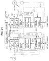
- Fig. 21 is an arrangement of the large capacity AC motor driving system according to the fourth embodiment of the present invention.
- the capacitors in the arrangement of the third embodiment are replaced by a common capacitor.
- the total capacitance of the capacitors required can be reduced to 1/n so that the entire system can be made compact.
- Fig. 22 shows an arrangement of the main circuit according to the fifth embodiment of the present invention.
- the main circuits of the converter and inverter are connected in multi-series to realize a large capacity system and the PWM switching at a high frequency.
- Fig. 22A shows one example of the multi-series connection circuit according to one phase. In a positive side arm, two GTO thyristors T1 and T2 are connected in series, and also in a negative side arm, two GTO thyristors are connected in series.
- One line extending from the middle point of a DC power source is connected with a junction between the GTO thyristors T1 and T2 through a diode in forward direction, and the other line is connected with a junction between the GTO thyristors T3 and T4 through another diode in a reverse direction.
- the input/output terminal of the phase concerned is connected with the junction between the GTO thyristors T2 and T3.
- each GTO thyristor is connected with a feedback diode and a snubber circuit.
- the phase voltage at the input/output terminal of the phase is as follows in accordance with the switching states of the GTO thyristors.
- the phase voltage is Ed/2 (Ed: DC power source voltage); when both GTO thyristors T2 and T3 are 'on', it is zero; and when both GTO thyristors are 'on', it is - Ed/2.
- the PWM operation waveforms shown in Fig. 14 which are the same as when the above multi-parallel inverter system is PWM-controlled in the spatial vector type SH system, and the phase voltage has the PWM pulse waveform at three levels. Accordingly, with respect to the line-to-line voltage, the PWM switching at the frequency twice as high as that of a carrier wave can be obtained.
- the inter-phase reactor and circulating current control circuit which are required in the multi-parallel system are not required so that the size of the entire system can be reduced.
Abstract
Description
- The present invention relates to a variable speed driving system for an AC electric motor, and more particularly to a large capacity variable speed driving system for driving an AC electric motor using a power converter device provided with a GTO (gate turn-off) thyristor.
- A previously proposed variable speed driving system for an AC electric motor with the largest capacity using an inverter is a system with 4000 kVA for general industry such as a pump and a fan. An example of this system is disclosed in e.g. "Toshiba Review" Vol. 43, No. 3 (1983) page 253.
- On the other hand, in the field of driving a roller that requires high response with a large capacity, an AC electric motor variable speed driving system based on a cycloconverter is adopted. Its examples are disclosed in Hitachi Hyoron Vol. 72, No.5 (1990), pp. 441 - 446; Toshiba Review Vol. 43, No. 3 (1988), p. 256; and Mitsubishi Electric Technical Report Vol. 62, No. 6 (1988), pp. 501 - 506. Until now, researches and achievements on adoption of an inverter in the field of large-capacity high speed -response such as driving of a roller have not published.
- When it is intended that in the above prior art, a large capacity inverter is realized, a GTO thyristor used as a switching device in a main circuit is a high- voltage large current device. But, with the device capacity increased, the permissible switching frequency of the device is reduced (the present limit is 100 - 150 Hz) so that adoption of the GTO thyristor does not have merits in that harmonics of the output wave from the inverter are increased, the torque ripple of a motor is increased, and loss in the snubber circuit for the GTO is increased (at the rate of square of the voltage).
- On the other hand, in the case of the cycloconverter, only one means that can be applied to the field of large-capacity high response, the power factor in a power source is limited to around 0. 6. In order to improve this power factor, a capacitor with a large capacitance for improving the power factor is required on the power source side. As a result, the resultant apparatus has a large scale.
- An object of the present invention is to provide a large capacity variable speed driving system for an AC electric motor which can provide the torque ripple of 1% or less of the AC electric motor by an inverter having a capacity of 2000 kVA or more provided with GTO thyristors.
- In order to attain the above object, a plurality of inverter units, each comprising a GTO thyristor with its permissible switching frequency of 500 Hz or more as switching devices in a main circuit, are connected in parallel in a multiplex manner, and a PWM (pulse width modulation) control device in an instantaneous spatial vector PWM control system or a spatial vector type SH (sub-harmonics) system controls the output from the inverter.
- Since the plurality of inverter units each provided with GTO thyristor with its permissible switching frequency of 500 Hz or more are connected in parallel in a multiplex manner, assuming that the PWM switching frequency for each inverter unit is fs, the equivalent switching frequency viewed from a motor side is doubled to provide 2fs, thereby realizing a high switching frequency. Thus, the inverter output voltage can be PWM-controlled precisely so that the harmonics of the inverter output current can be reduced thereby to decrease the torque ripple of the motor. Also, since the PWM control device in the instantaneous spatial vector system or the spatial vector type SH system selects the voltage vector along the magnetic flux circle of the electric motor to control the output voltage from the inverter, the torque ripple of the electric motor can be further reduced. By combining the components mentioned above, the torque ripple of 1% or less in the motor can be attained.
- If the present invention is applied to driving a vehicle, because of high efficiency due to reduction of snubber loss, a cooling system can be miniaturized to reduce the weight of the vehicle body. Also, if the present invention is applied to AC driving for general industry. e.g., driving a pump and a fun, because of high efficiency, the effect of reducing energy can be further improved.
- In accordance with the present invention, since a plurality of inverter units each provided with a GTO thyristor with its permissible switching frequency of 500 Hz or more are connected in parallel in a multiplex manner, the equivalent switching frequency viewed from a motor side can be changed into a high switching frequency. Thus, the inverter output voltage can be PWM-controlled precisely so that the harmonics of the inverter output current can be reduced thereby to decrease the torque ripple of the motor. Also, since the PWM control device in the instantaneous spatial vector system or the spatial vector type SH system selects the voltage vector along the magnetic flux circle of the electric motor to control the output voltage from the inverter, the torque ripple of the electric motor can be further reduced. By combining the components mentioned above, a variable speed system for a large capacity AC motor which has a characteristic of the torque ripple of 1% or less in the motor can be provided.
- The above and other objects and advantages of the present invention will be apparent from the following description taken in conjunction with the accompanying drawings
-
- Fig. 1 is a view showing an arrangement of the large capacity AC electric motor variable speed system according to the first embodiment of the present invention;
- Fig. 2 is a view showing a detailed arrangement of the snubber circuit of the converter main circuit in Fig. 1;
- Figs. 3A to 3F and 4A to 4F are views for explaining the operation of the snubber circuit shown in Fig. 2;
- Figs. 5 to 8 are other detailed arrangements of the snubber circuit of the converter main circuit in Fig. 1;
- Fig. 9 is a table showing the actual measurement results of the loss characteristic in a power converter according to the present invention;
- Fig. 10 is a view showing a detailed arrangement of the speed/vector control unit in Fig. 1;
- Figs. 11 and 12 are views for explaining the operation of instantaneous spatial vector PWM control;
- Fig. 13 is a view showing an arrangement for the PWM control in a spatial vector type SH system;
- Figs. 14 and 15 are waveform charts of the PWM control in the spatial vector type SH system;
- Fig. 16 is a view of the actual measurement result of the speed response characteristic;
- Fig. 17 is a view showing a detailed arrangement for power factor arrangement and voltage control in Fig. 1;
- Fig. 18A and 18B are waveform charts of the characteristic obtained by the control by the arrangement shown in Fig. 17;
- Fig. 19 is a view of an arrangement of the large capacity AC power electric power variable speed system according to the second embodiment of the present invention;
- Fig. 20 is a view of an arrangement of the large capacity AC power electric power variable speed system according to the third embodiment of the present invention;
- Fig. 21 is a view of an arrangement of the large capacity AC power electric power variable speed system according to the fourth embodiment of the present invention; and
- Fig. 22 is a view of an arrangement of a main circuit unit according to the fourth embodiment of the present invention.
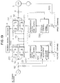
- Referring now to Fig. 1, an explanation will be given of the first embodiment of the large capacity AC electric motor variable speed system according to the present invention. In Fig. 1, an
inverter 100 is composed ofinverter units converter 200 is composed ofconverter units elements capacitors 71 and 72, respectively. Theoutput terminals interphase reactor 92, and the middle point of theinterphase reactor 92 is connected with an ACelectric motor 5. The input terminals of theother converter units interphase reactor 93, and the middle point ofinterphase reactor 93 is connected with anAC power source 6. It should be now noted that the GTO thyristors constituting a main circuit of the above inverter and converter units are connected with a snubber circuit and a snubberenergy recovering circuit 4 for recovering the electric energy stored in the snubber circuit to a DC power source on the side of the above capacitors. Theinverter 100 and theconverter 200 are controlled by acontrol circuit 300. Specifically, in thecontrol circuit 300, theinverter 100 is controlled by a speed/vector control circuit 330 and an instantaneous spatial vectorPWM control circuit 310, and theconverter 200 is controlled by a power factor adjustment/voltage control circuit 340 and another instantaneous spatial vectorPWM control circuit 320. - A detailed explanation will be given of the components of the above system. The snubber
energy recovering system 4 is constructed as shown in Fig. 2 for each inverter unit and for converter unit. A snubber circuit is composed of afirst capacitor 2100, asecond capacitor 2200 and twodiodes diode 2300 is connected with the positive terminal of a main switching circuit through thefirst capacitor 2100 and the cathode of thediode 2400 is connected with the negative terminal of the main switching circuit. The common junction of thediodes second capacitor 2200. - A snubber recovering circuit is composed of a
diode 3800, atransformer 3000 and aresistor 3100. The primary winding of thetransformer 3000 is connected in parallel with the series connection of thediodes first capacitor 2100 whereas the secondary winding of thetransformer 3000 is connected with the DC terminal through thediode 3800 for preventing a current from flowing a reverse direction. Theresistor 3100 for reset is connected across the primary winding of thetransformer 3000 so that part of the discharged current due to the snubber energy is bypassed to recover the snubber energy through theresistor 3100; thus, the excited current of thetransformer 3000 is attenuated rapidly to prevent the magnetic saturation of an iron core. In this way, the current which flows continuously even when the snubber recovering energy is not being recovered can be reset rapidly by theresistor 3100 so that the magnetic saturation of the iron core can be prevented and thus the transformer can be miniaturized. - Referring to Figs. 3A to 3F and 4A to 4F, the operation of recovering snubber energy will be explained below.
- Figs. 3A to 3F show the circuit operation in which the current flow state of a positive arm is returned to the same state via the current flow state of a negative arm. In the state of Fig. 3A, a GTO thyristor is 'on' and an current iL from is supplied to an AC terminal. In this state, if an off-gate signal is applied to the
GTO thyristor 1100, the current iL having flowed until now flows along the path (capacitor 2100 - diode 2300 - capacitor 2200) as shown in Fig. 3B. Then, a switching surge is absorbed and the energy with the polarity as shown stored in thecapacitor 2200 is discharged to the AC terminal. In the state is Fig. 3B, since theGTO thyristor 1100 is changed from 'on' to 'off', with the polarity of the current iL being positive (flowing-out direction) the polarity of the voltage at the AC terminal is changed from positive to negative; namely the state of Fig. 3B is equivalent to the state of delay power factor, i.e., delayed-phase driving state. On the other hand, thecapacitor 2100 is excessively charged. - In the return mode as shown in Fig. 3C in which the current iL flows to the negative mode, the charge stored in the
capacitor 2100 are discharged along the passage shown in dotted line so that a discharged current is flows towards the primary winding of thetransformer 3000. Thus, the current iS2 that is inversely proportional to the number of the primary and secondary windings flows to the secondary winding side of thetransformer 3000 so that the energy is recovered to the DC power source side. - As shown in Fig. 3D, after an off-gate signal is applied to the
GTO thyristor 1200, when an on-gate signal is applied to the GTO thyristor again, thecapacitor 2200 is charged and the switching surge is absorbed. The current flows into theGTO thyristor 1100 to be returned to the state as shown in Fig. 3F (that is the same as that of Fig. 3A) via the state of Fig. 3D. Incidentally, in the current commutation operation of Figs. 3C to 3F, the output voltage polarity is changed from negative to positive with the load current being positive so that the states of Figs. 3C to 3F are equivalent to the advanced power factor state, i.e., an advanced-phase driving state. - Figs. 4A to 4F show the circuit operation in which the current flow state of the negative arm is returned to the same state via the current flow state of the positive arm. The current commutation operations in Figs. 3A to 3D are commutation operations in the delayed-phase mode as in Figs. 3A to 3C. The current commutation operations in Figs. 4D to 4F are the commutation operations in the advanced-phase mode as in Figs. 3C to 3F. When the state of Fig. 4D is shifted to that of Fig. 4E, the energy stored in the
capacitor 2200 cannot be released to the AC side owing to the current flowing from the AC terminal. Thus, when theGTO thyristor 1200 turns on, the energy is recovered to the DC side along the current path of (1) and (2) shown in Fig. 4E. In this way, the surge energy generated owing to the turn-off of the GTO thyristor is absorbed into the capacitor in the snubber circuit and the absorbed energy is recovered to the AC side or DC side as power in the both driving modes of phase advancing and phase delaying. - Fig. 5 shows an arrangement for snubber energy recovering in which a transformer is not provided for each phase unlike Fig. 2 but for all the phases. This arrangement permits the snubber recovering system to be further small-sized.
- Figs. 6 and 7 show an arrangement including GTO thyristors connected in series to cause the converter to have a large capacity. It should be noted that a transformer is not provided for each phase but for all the phases. In Figs. 6 and 7, 410, 420 and 430 denote snubber circuits each provided with a diode, a capacitor and a resistor. The snubber circuits are individually connected with each GTO thyristor so that the sharing voltage of each of the GTO thyristors connected in series can be equalized.
- Although in this embodiment, the
transformer 3000 is included in the snubber energy recovering circuit, a DC/DC converter 3200 may be used in place of the transformer as shown in Figs. 8A and 8B. In comparison to Fig. 8A, the arm arrangement in Fig. 8B is composed of GTO thyristors connected in series. In Figs. 8A and 8B, acapacitor 2100 is always charged to a DC voltage Ed; the excessively charged energy from the voltage Ed is recovered to the DC side. - The energy recovering system described above can provide the energy recovering rate of 80% or more. This is because in the case of using a transformer, the resistor for reset connected in parallel with the transformer has loss of 10 - 20%, and also in the case of using a DC/DC converter, the converter has loss at the same degree.
- Fig. 9 shows the loss and efficiency of a power converter when an induction motor is driven by the power converter in which the converter and inverter are connected in multi-parallel. With the capacitance of 2700 kVA (1350 kVA x 2) of the power converter concerned, the turn on/off switching loss of GTO is reduced to 33 kW; the snubber loss can be reduced to 40 kW by the energy recovering circuit; and the other loss of e.g. an inter-phase reactor is 29 kW. The total efficiency of the converter of 96.2% could be attained.
- Fig. 10 shows an arrangement of the speed/
vector control circuit 330 included in Fig. 1. This arrangement is composed of a speed adjusting device 3302 for generating a torque current command Iq* on the basis of a difference between a speed command ω* and the rotating speed ω of the three-phase electric motor by a speed detector 51, a field weakening control circuit 3301 for generating an excited current command Id* from the rotating speed ωr, a slip calculator 3308 for calculating the slipping frequency ws on the basis of the torque current command and the excited current command, an adder 3309 for adding the slipping frequency and the rotating speed to calculate a first order frequency ω₁*, a converter 3307 for converting the three-phase AC currents iu - iw detected by a current detector 81 into the currents Id and Iq corresponding to the torque and excited component, a DC current adjusting device 3303 for generating a voltage command Vq* from the difference between the command value Iq* and detected value Iq of the torque current and for another voltage command Vd* from the difference between the command value and detected value of the excited current, a converter 3304 for converting the above Vq* and Vd* into three-phase voltage commands vu' to vw', a converter 3305 for converting the current component commands Iq* and Id* into three-phase current commands iu* to iw', an AC current adjusting device 3306 for generating corrected voltages Δvu to Δvw from the differences between the these three-phase voltage commands iu* to iw* and detected values, and an adder 3310 for adding the three-phase voltage commands and the corrected voltages to calculate first order voltage commands vu* to vw*. - An instantaneous spatial vector
PWM control unit 310 serves to PWM-control the output voltage from the inverter on the basis of the above first order voltage commands. In the case where the inserters are in multi-parallel connection, thecontrol unit 310 is provided with a circulatingcurrent control unit 3101 for suppressing the current circulating through the inverter units. Incidentally, although the above control arrangement is shown in block form in which the signals are processed in an analog manner, the control/processing in the present invention is actually carried out using a microcomputer. - Now it should be noted that the response characteristic of the speed control system (ASR) depends on the magnitude of the inertia of a load and the response characteristic of the current control system (ACR). It is generally recognized that stabilized speed control can be made if the response of ACR is 5 to 10 times as large as that of ASR. In vector control system according to this embodiment, the DC ACR for Id and Iq is used so that all the vectors can be processed in DC magnitudes. The DC ACR can control the current in a more stabilized manner and with less control error than an AC ACR dealing with an instantaneous value and thus is not required to have a higher current control response than in the AC ACR. Additionally, an
AC ACR 3306 provided in this embodiment is provided to reduce only the output current distortion due to the dead time of the switching devices in the main circuit. - Further, in the vector control according to this embodiment, the respective components of the torque current and magnetic flux are controlled individually so that the stabilized high-speed speed control characteristic for a load change (load torque change) can be obtained.
- Now referring to Figs. 11A and 11B, an explanation will be explained on the instantaneous vector
PWM control unit 310 included in Fig. 1. - The three-phase single inverter comprises eight switching states. Fig. 11A shows these switching states in a spatial coordinate. These states are expressed as output voltage vectors of V₀ to V₇. A voltage command is also managed as a spatial vector, and the voltage command vector V* is expressed as a first order combination of the output vectors from the inverter. The switching state corresponding to the voltage vector is produced during the pulse duration in proportion to its coefficient.
- Then, in order to obviate any redundant switching, with respect to the output voltage vector, only the vector located at the apex of a triangle including the voltage command vector is selected. In the case of Fig. 11A, the selected vectors are V₁ and V₂, and zero vectors of V₀ and V₇. Further, in order to reduce the number of times of switching, the voltages are outputted in the order of V₀ - V₁ - V₂ - V₇ - V₂ - V₁ - V₀. The outputting time tk of each of the voltage vectors can be calculated.


where T is a sampling period.
Although the sum of t0 and t7 can be calculated from the above two equations, they cannot be separated. So, the following condition is also given,

This is because in outputting the zero voltage vector, the torque ripple can be made smaller by outputting it during equal times than increasing the time taken to be once outputted since its degree of out-of-phase from the command value. - Specifically, as shown in Fig. 11C, the optimum voltage vectors V₀ to V₇ are selected within a angle Δϑ within which the crossing magnetic flux vector φ crossing the secondary winding of the electric motor during a sampling period T advances. The crossing magnetic flux vector φ makes an approximately circle locus rotating at the angular speed of ω. Thus, the torque ripple attendant on the change in the magnetic flux is reduced.
- The phase voltages of the inverter viewed from the change in the pulse durations due to the instantaneous spatial vector PWM control are shown in Fig. 12. The maximum value is √


- The PWM system according to this embodiment has the following advantages.
- (1) By equalizing the output times of the zero voltage vectors (V₀ and V₇), the torque ripple can be reduced (the torque ripple of 1% or less can be attained at the switching at 1 kHz).
- (2) The maximum voltage using rate can be improved by 15% as compared with the conventional sine wave modulation SH system. Therefore, the input DC voltage for the inverter may be smaller by 15% so that the switching device with a relatively low withstand voltage.
- (3) Since the PWM operations corresponding to three phases are collectively processed, the operation time required is short and so the burden for the microcomputer used can be relaxed.
- However, in the case where the multiple inverter is to be controlled, the number of output voltage vectors is increased to 19 and the number of combined modes is increased to 24 so that it takes a long time to only decide the mode.
- In order to obviate such an inconvenience, the multiple inverter will be PWM-controlled by the spatial vector type SH system described below. The principle of this system is to form the modulated wave analogous to the phase voltage (Fig. 12) obtained by the instantaneous spatial vector PWM control and to form a PWM pulse on the basis of the modulated using an algorithm in the SH system.
- Fig. 13 shows an arrangement of the spatial vector type SH system for PWM controlling the parallel-multi inverter system in block form. A voltage command means 5000 generates sine-wave three phase instantaneous voltage commands Vu* - Vw*. A voltage
command comparing means 6000 compares the values of these three phase instantaneous voltage commands to produce an intermediate value among them. The value V₀ that is 1/2 of the intermediate value of the voltage commands is added to the above respective phase voltage commands to form modulated wave signals Vu** - Vw** which are in turn supplied tocomparators comparator 6100 compares the above modulated wave signals Vu** - Vw** with the first carrier wave ec1 for each phase to form PWM signals for the first unit inverter. Likewise, thecomparator 6110 compares the above modulated wave signals Vu** - VW** with the second carrier wave ec2 for each phase to form PWM signals for the second unit inverter. A circulating current control means 3101 processes the thus formed PWM signals so as to suppress the current circulating through the unit inverters. - Figs. 14A to 14F show the PWM operation waveform of the multi-inverter system in the spatial vector type SH system. The voltage command correction signal V₀ is the value that is 1/2 of the intermediate value among the three phase voltage commands. The modulated wave Vu** (only the U phase is shown in Fig. 14C) is obtained by adding the corrected signal V₀ to the voltage command for each phase; this modulated wave is equivalent to the phase voltage waveform obtained by the instantaneous spatial vector system as shown in Fig. 12. The voltage (Figs. 14A and 14B) for each phase of the inverter results in a three-level PWM pulse waveform obtained by comparing the modulated wave with the double carrier waves. As seen from Fig. 14F, in terms of the line-to-line voltage, the PWM switching frequency is twice as high as the carrier wave frequency.
- It can be understood from the above description that if the multi-inverter system is PWM-controlled by the spatial vector type SH system, with the same output PWM pulse waveform as in the instantaneous spatial vector system, the time required for the PWM operation can be reduced to 1/5 or less. Thus, the burden to the microcomputer for performing the PWM operation can be relaxed so that the number of times of sampling in the current/speed control system can be increased to that degree, thus improving the response characteristic of the control system.
- Figs. 15A and 15B show operation waveforms when an induction motor is driven by the multi-inverter system. The specifications at this time are as follows: A unit inverter has a capacitance of 1350 kVA, an input DC voltage of 4 kV, a switching frequency of 500 Hz, an output frequency of 40 Hz and the induction motor has an output power of 2000 kW, an input voltage of 2000 V and four poles and four poles. Fig. 15A shows the waveforms when the multi-inverter system is PWM-controlled by the spatial vector type SH system, and Fig. 15B shows the waveforms when it is PWM-controlled by the sine wave modulated type SH system. In the sine wave modulated type SH system, the voltage command is saturated so that the phase voltage in a pulse thinned-out state ( PWM control is not made at the center of the phase voltage); thus, the current ripple and torque ripple are relatively large.
- On the other hand, in the spatial vector type SH system, the modulated waveform is flat in the neighborhood of the maximum value of the voltage command so that the voltage command is not saturated and so the phase voltage does not reach the pulse thinned-out state to provide substantially fixed pulse intervals. The pulse intervals of the line-to-line voltage are also substantially fixed which means an improved voltage using rate,. The torque ripple can be reduced to 1% or less as shown.

- Fig. 16 shows the response characteristic of a speed stepwise change. As seen from Fig. 16, the actual speed of the electric motor swiftly responds to the stepwise change to provide the response characteristic of 80 rad/s.
- Referring to Fig. 17, an explanation will be given of an arrangement of the power factor adjustment / voltage control unit 341 included in the control means 300 for the
converter 200 in Fig. 1. Its schematic arrangement is the same as that of the control device for the inverter as shown in Fig. 10 but different from the following points. On the input side of the converter, three-phase AC voltage phases and three-phase AC currents are detected bydetectors converter 3404 detects valid and invalid currents iq and id in DC magnitudes from the three-phase AC currents iR, is and iT. A voltage adjusting circuit (AVR) is provided to cause the DC current Ed detected on the output side of the converter to coincide with the command value Ed*. A valid current command iq* is obtained from the sum of the output from the AVR and the DC current Idc after the converter output is smoothed by a capacitor. Using this command thus obtained, a DC current adjuster (Id, Iq - ACR) 3402 adjusts the DC currents so that the invalid current becomes zero and the valid current becomes its command value, thus producing DC voltage signals corresponding respective components. These voltage signals are supplied to a coordinateconverter 3406 to provide three phase AC voltage signals. An AC current adjuster (AC - ACR) 3403 serves to reduce an input current distortion to generate corrected voltage signals on the basis of differences between the values obtained by converting id* and iq* into three phase AC current command signals by a coordinateconverter 3405 and the above detected three phase AC current values. The corrected voltage signals are added to the output signals from the coordinate converter to provide three phase command signals VR *, Vs * and VT *. An instantaneous spatial vectorPWM control unit 320 creates PWM pulses on the basis of the three phase command signals and PWM-controls theconverter 200 using these PWM pulses. It should be noted that the instantaneous spatial vectorPWM control unit 320 performs the same operation as the above instantaneous spatialPWM control unit 310 for theinverter 100. Incidentally, in the case of using the multi-inverter system, in order to shorten the PWM operation processing time, thePWM control unit 310 is operated in the above spatial vector type SH system. - Figs. 18A and 18B show waveforms of the phase voltage and phase current of the three-phase AC power source on the input side of the converter system in the case the motor is driven by the multi-parallel converter system. The converter system has the specifications of a capacity of 1350 kVA for each unit, a power source voltage of 2 kV, a power source frequency of 50 Hz and a switching frequency of 500 Hz.
- Fig. 18A is directed to a power running whereas Fig. 18B is directed to a regenerative running. In both cases, although the current waveform is composed of a basic wave and a ripple slightly overlapping therewith due to the PWM switching at 1 kHz, the phase difference between the voltage and the basic wave of the current is 8° or less so that the power factor for the basic wave of about 99% can be obtained.
- In accordance with the first embodiment of the present invention, in the large capacity (2000 kVA or more) variable speed driving system for an AC electric motor, in the case where a GTO thyristor with its permissible switching frequency of 500 Hz is used as a switching device in the main circuit of each of a converter and an inverter constituting an electric power converter, a plurality of inverters are connected in parallel in a multiplex manner and the output voltages from the inverters are controlled through instantaneous spatial vector PWM control. In this way, the torque ripple of the AC electric motor can be reduced to 1% or less. Since the snubber circuit to be connected with the switching GTO thyristors in the main circuits in the converter and the inverter is provided with snubber energy recovering means, the efficiency of power conversion can be improved to 95% or more. The vector control for the motor, multi-parallel connection of the inverters and the PWM control in instantaneous spatial vector or spatial vector type SH system can improve the speed response of the motor to 60 rad/s or more. Further, the multi-parallel connection of the converters, the power factor adjusting circuit and the PWM control in instantaneous spatial vector or spatial vector type SH system can improve the power factor of an AC power source to 98% or more.
- Further, in order to provide the above advantages, in the first embodiment, GTO thyristors with their permissible switching frequency of 500 Hz are used in the main circuits of the power converters in multi-parallel connection, but in the case of using a single power converter, GTO thyristors with their permissible switching frequency of 1 kHz or more may be used to provide the same advantage. In this case, however, if the permissible switching frequency is enhanced, the permissible switching current must be decreased in view of the characteristic of GTO thyristor. As a result, the capacitance of the power converter is decreased by half of the previous case, thus providing a large capacity variable speed AC motor driving system with the capacity of 1000 kVA.
- Fig. 19 is an arrangement of the large capacity variable speed AC motor driving system according to the second embodiment of the present invention. In the first embodiment shown in Fig. 1, the
unit converter 210 and theunit inverter 110 are connected through thecapacitor 71, and also theother unit converter 220 and theother unit inverter 120 are connected by the other capacitor 72. On the other hand, in this embodiment, two unit converters and two unit inverters are connected with each other through acommon capacitor 73 but not through the above two capacitors. In accordance with this embodiment, the capacitance of capacitors constituting a DC circuit can be reduced to about 1/2 of the total capacitance in the first embodiment so that the capacitor size can be increased. - Fig. 20 shows an arrangement of the large capacity variable speed AC motor driving system according to the third embodiment of the present invention. In the embodiment shown in Fig. 1, the motor is a three phase motor whereas in this embodiment, the motor used is a multi-phase (six phase, nine phase, ... , 3n (n = 2, 3, 4, ...) phase) motor. The system including such a multi-phase motor can be easily realized by increasing the number of sets each composed of the three-
phase converter 200 andinverter 100 in accordance with the number of phases of the motor used. In accordance with this embodiment, the large capacity of the system can be realized and also adoption of the motor permits the torque ripple to be reduced. - Fig. 21 is an arrangement of the large capacity AC motor driving system according to the fourth embodiment of the present invention. In this embodiment, the capacitors in the arrangement of the third embodiment are replaced by a common capacitor. In accordance with this embodiment, in the case of 3n phases, the total capacitance of the capacitors required can be reduced to 1/n so that the entire system can be made compact.
- Fig. 22 shows an arrangement of the main circuit according to the fifth embodiment of the present invention. Whereas in the embodiments previously described, in order to realize large capacity of the system, the converters and the inverters are connected in multi-parallel, respectively, in this embodiment, the main circuits of the converter and inverter are connected in multi-series to realize a large capacity system and the PWM switching at a high frequency. Fig. 22A shows one example of the multi-series connection circuit according to one phase. In a positive side arm, two GTO thyristors T1 and T2 are connected in series, and also in a negative side arm, two GTO thyristors are connected in series. One line extending from the middle point of a DC power source is connected with a junction between the GTO thyristors T1 and T2 through a diode in forward direction, and the other line is connected with a junction between the GTO thyristors T3 and T4 through another diode in a reverse direction. The input/output terminal of the phase concerned is connected with the junction between the GTO thyristors T2 and T3. Although not shown, it is needless to say that each GTO thyristor is connected with a feedback diode and a snubber circuit.
- In the arrangement of the main circuit described above, the phase voltage at the input/output terminal of the phase is as follows in accordance with the switching states of the GTO thyristors. When both GTO thyristors T1 and T2 are 'on', the phase voltage is Ed/2 (Ed: DC power source voltage); when both GTO thyristors T2 and T3 are 'on', it is zero; and when both GTO thyristors are 'on', it is - Ed/2. In this way, the PWM operation waveforms shown in Fig. 14 which are the same as when the above multi-parallel inverter system is PWM-controlled in the spatial vector type SH system, and the phase voltage has the PWM pulse waveform at three levels. Accordingly, with respect to the line-to-line voltage, the PWM switching at the frequency twice as high as that of a carrier wave can be obtained.
- In accordance with this embodiment, the inter-phase reactor and circulating current control circuit which are required in the multi-parallel system are not required so that the size of the entire system can be reduced.
- If several embodiments of the present invention hitherto described is applied to driving a roller, the resultant low torque ripple and high response can enhances the precision of rolling.
Claims (10)
- A large capacity variable speed driving system for driving an AC motor by an inverter having a capacity of 2000 kVA or more including self-igniting elements for converting DC power into AC power comprising:
an inverter system (100) composed of a plurality of unit inverters (110, 120) connected in parallel in a multiplex manner; and
a PWM (pulse width modulation) control device (310) for controlling the output voltage from said inverter system,
wherein said self-igniting elements are GTO thyristors with their switching frequency of 500 Hz or more, and said PWM control device is an instantaneous spatial vector PMW system or spatial vector type SH (sub-harmonic) system (310). - A large capacity variable speed driving system for driving an AC motor by an inverter having a capacity of 2000 kVA or more including self-igniting elements for converting DC power into AC power comprising:
an inverter system (100) composed of a plurality of unit inverters (110, 120) connected in series in a multiplex manner for one arm (Fig. 6); and
a PWM (pulse width modulation) control device (310) for controlling the output voltage from said inverter system,
wherein said self-igniting elements are GTO thyristors with their switching frequency of 500 Hz or more, and said PWM control device is an instantaneous spatial vector PMW system or spatial vector type SH (sub-harmonic) system (310). - A large capacity variable speed driving system for an AC motor according to claim 1 or 2, wherein the number of winding phases of said AC motor and that of output phases in said inverter system are 6 or more.
- A large capacity variable speed driving system for an AC motor according to claim 1 or 2 further comprising vector control means (330) for controlling the said AC motor in such a manner that the torque component and magnetic flux component in the primary current of said AC motor are separated.
- A large capacity variable speed driving system for an AC motor according to claim 1 or 2, further comprising:
a converter system (200) for converting an AC power source into said DC power, which is composed of unit converters (210, 211) connected in parallel in a multiplex manner; and
means (300) for controlling said converter system,
wherein said unit converter includes a GTO thyristor with its switching frequency of 500 Hz or more, and said control means (300) comprises a power factor adjusting circuit (340) and instantaneous spatial vector system or spatial vector type SH system PWM control means (320) for controlling the output signal from said power factor adjusting circuit. - A large capacity variable speed driving system for an AC motor according to claim 1 or 2, further comprising:
a converter system (200) for converting an AC power source into said DC power, which is composed of unit converters (210, 211) connected in series in a multiplex manner (Fig. 6); and
means (300) for controlling said converter system,
wherein said unit converter includes a GTO thyristor with its switching frequency of 500 Hz or more, and said control means (300) comprises a power factor adjusting circuit (340) and instantaneous spatial vector system or spatial vector type SH system PWM control means (320) for controlling the output signal from said power factor adjusting circuit. - A large capacity variable speed driving system for an AC motor according to any one of claims 1, 2, 5 and 6, further comprising a snubber circuit provided with snubber energy recovering means (4) for recovering the loss generated in the snubber to DC power on the inverter input side.
- A large capacity variable speed driving system for an AC motor according to any one of claims 1 to 7, wherein it is applied to driving a roller.
- A large capacity variable speed driving system for an AC motor according to any one of claims 1 to 7, wherein it is applied to driving a pump.
- A large capacity variable speed driving system for an AC motor according to any one of claims 1 to 7, wherein it is applied to driving a fan, or a vehicle or linear motor.
Applications Claiming Priority (2)
| Application Number | Priority Date | Filing Date | Title |
|---|---|---|---|
| JP2323155A JP2954333B2 (en) | 1990-11-28 | 1990-11-28 | AC motor variable speed system |
| JP323155/90 | 1990-11-28 |
Publications (2)
| Publication Number | Publication Date |
|---|---|
| EP0488201A1 true EP0488201A1 (en) | 1992-06-03 |
| EP0488201B1 EP0488201B1 (en) | 1997-03-05 |
Family
ID=18151698
Family Applications (1)
| Application Number | Title | Priority Date | Filing Date |
|---|---|---|---|
| EP91120256A Expired - Lifetime EP0488201B1 (en) | 1990-11-28 | 1991-11-27 | Large capacity variable speed driving system for AC electric motor |
Country Status (5)
| Country | Link |
|---|---|
| US (1) | US5298848A (en) |
| EP (1) | EP0488201B1 (en) |
| JP (1) | JP2954333B2 (en) |
| DE (1) | DE69124934T2 (en) |
| FI (1) | FI915608A (en) |
Cited By (6)
| Publication number | Priority date | Publication date | Assignee | Title |
|---|---|---|---|---|
| EP0746864A1 (en) * | 1993-03-15 | 1996-12-11 | L & I RESEARCH, INC. | Solid state circuit breaker |
| DE19653182A1 (en) * | 1996-12-20 | 1998-06-25 | Siemens Ag | Drive device for roll stands |
| EP1204197A2 (en) * | 2000-10-13 | 2002-05-08 | DaimlerChrysler Rail Systems GmbH | Decive and method for network-side intermediate voltage regulation |
| WO2010052048A1 (en) * | 2008-11-10 | 2010-05-14 | Siemens Ag Österreich | Three-phase ac power controller |
| WO2011095212A3 (en) * | 2010-02-03 | 2011-11-17 | Abb Technology Ag | Switching module to limit and/or break the current of an electric power line |
| US20200395867A1 (en) * | 2018-02-20 | 2020-12-17 | Mitsubishi Electric Corporation | Power semiconductor module and power conversion apparatus including the same |
Families Citing this family (46)
| Publication number | Priority date | Publication date | Assignee | Title |
|---|---|---|---|---|
| FR2714234B1 (en) * | 1993-12-16 | 1996-08-23 | Telemecanique | Power control system for an asynchronous motor. |
| US5491622A (en) * | 1994-01-07 | 1996-02-13 | Delco Electronics Corp. | Power converter with emergency operating mode for three phase induction motors |
| US6054837A (en) * | 1994-06-28 | 2000-04-25 | Borealis Technical Limited | Polyphase induction electrical rotating machine |
| JP3675014B2 (en) * | 1995-06-08 | 2005-07-27 | 株式会社デンソー | Inverter control device |
| US5801519A (en) * | 1996-06-21 | 1998-09-01 | The Board Of Trustees Of The University Of Illinois | Self-excited power minimizer/maximizer for switching power converters and switching motor drive applications |
| US6570361B1 (en) * | 1999-02-22 | 2003-05-27 | Borealis Technical Limited | Rotating induction apparatus |
| DE19647637A1 (en) * | 1996-11-18 | 1998-05-28 | Siemens Ag | Rolling mill with at least one roll stand with three-phase drive system |
| US5796599A (en) * | 1997-03-12 | 1998-08-18 | Reliance Electric Industrial Company | Self-powered gate driver board |
| KR100319932B1 (en) * | 1998-10-07 | 2002-04-22 | 장병우 | Overvoltage prevention device of motor |
| US6864661B2 (en) * | 1999-02-22 | 2005-03-08 | Borealis Technical Limited | Rotating induction apparatus |
| US6922037B2 (en) * | 1999-02-22 | 2005-07-26 | Borealis Technical Limited | Rotating induction apparatus |
| US8364342B2 (en) * | 2001-07-31 | 2013-01-29 | Immersion Corporation | Control wheel with haptic feedback |
| JP2004015892A (en) * | 2002-06-05 | 2004-01-15 | Toshiba Corp | Inverter controlling device and electric vehicle |
| US6963182B2 (en) * | 2002-11-29 | 2005-11-08 | Toyoda Koki Kabushiki Kaisha | Motor control device and motor control method |
| SE0302430L (en) * | 2003-09-11 | 2004-09-28 | Abb Research Ltd | Rotating electric motor |
| US7208891B2 (en) * | 2005-05-06 | 2007-04-24 | York International Corp. | Variable speed drive for a chiller system |
| US7081734B1 (en) | 2005-09-02 | 2006-07-25 | York International Corporation | Ride-through method and system for HVACandR chillers |
| US7332885B2 (en) * | 2005-09-02 | 2008-02-19 | Johnson Controls Technology Company | Ride-through method and system for HVAC&R chillers |
| JP4932301B2 (en) * | 2006-03-28 | 2012-05-16 | 川崎重工業株式会社 | Inverter control device and motor control system using the same |
| US7309973B2 (en) * | 2006-04-24 | 2007-12-18 | Power Conservation Ltd | Mitigation of harmonic currents and conservation of power in non-linear load systems |
| US7459877B2 (en) * | 2006-08-30 | 2008-12-02 | Westinghouse Electric Co., Llc | Solid state reversing AC motor starter with DC power source |
| US8014110B2 (en) | 2007-01-22 | 2011-09-06 | Johnson Controls Technology Company | Variable speed drive with integral bypass contactor |
| US8495890B2 (en) * | 2007-01-22 | 2013-07-30 | Johnson Controls Technology Company | Cooling member |
| US8149579B2 (en) * | 2008-03-28 | 2012-04-03 | Johnson Controls Technology Company | Cooling member |
| WO2008137276A1 (en) | 2007-05-08 | 2008-11-13 | Johnson Controls Technology Company | Variable speed drive |
| JP2008295161A (en) * | 2007-05-23 | 2008-12-04 | Daikin Ind Ltd | Power conversion device |
| US8174853B2 (en) * | 2007-10-30 | 2012-05-08 | Johnson Controls Technology Company | Variable speed drive |
| US7957166B2 (en) * | 2007-10-30 | 2011-06-07 | Johnson Controls Technology Company | Variable speed drive |
| US20090196764A1 (en) * | 2008-02-04 | 2009-08-06 | Fogarty James M | High frequency electric-drive with multi-pole motor for gas pipeline and storage compression applications |
| US8353174B1 (en) | 2008-10-03 | 2013-01-15 | Johnson Controls Technology Company | Control method for vapor compression system |
| WO2011108169A1 (en) * | 2010-03-03 | 2011-09-09 | 株式会社安川電機 | Inverter device and control method thereof |
| US8982593B2 (en) | 2012-04-27 | 2015-03-17 | Rockwell Automation Technologies, Inc. | Cascaded H-Bridge (CHB) inverter level shift PWM with rotation |
| US8619446B2 (en) | 2012-04-27 | 2013-12-31 | Rockwell Automation Technologies, Inc. | Cascaded H-bridge (CHB) inverter level shift PWM with rotation |
| US9007787B2 (en) | 2012-08-13 | 2015-04-14 | Rockwell Automation Technologies, Inc. | Method and apparatus for bypassing Cascaded H-Bridge (CHB) power cells and power sub cell for multilevel inverter |
| US9425705B2 (en) | 2012-08-13 | 2016-08-23 | Rockwell Automation Technologies, Inc. | Method and apparatus for bypassing cascaded H-bridge (CHB) power cells and power sub cell for multilevel inverter |
| US9240731B2 (en) | 2013-03-18 | 2016-01-19 | Rockwell Automation Technologies, Inc. | Power cell bypass method and apparatus for multilevel inverter |
| FR3004299B1 (en) * | 2013-04-05 | 2016-10-28 | Valeo Equip Electr Moteur | METHOD AND DEVICE FOR CONTROLLING A POLYPHASE INVERTER |
| US9083230B2 (en) | 2013-06-20 | 2015-07-14 | Rockwell Automation Technologies, Inc. | Multilevel voltage source converters and systems |
| US9520800B2 (en) | 2014-01-09 | 2016-12-13 | Rockwell Automation Technologies, Inc. | Multilevel converter systems and methods with reduced common mode voltage |
| US9325252B2 (en) | 2014-01-13 | 2016-04-26 | Rockwell Automation Technologies, Inc. | Multilevel converter systems and sinusoidal pulse width modulation methods |
| US9559541B2 (en) | 2015-01-15 | 2017-01-31 | Rockwell Automation Technologies, Inc. | Modular multilevel converter and charging circuit therefor |
| US9748862B2 (en) | 2015-05-13 | 2017-08-29 | Rockwell Automation Technologies, Inc. | Sparse matrix multilevel actively clamped power converter |
| US9812990B1 (en) | 2016-09-26 | 2017-11-07 | Rockwell Automation Technologies, Inc. | Spare on demand power cells for modular multilevel power converter |
| US10158299B1 (en) | 2018-04-18 | 2018-12-18 | Rockwell Automation Technologies, Inc. | Common voltage reduction for active front end drives |
| US11211879B2 (en) | 2019-09-23 | 2021-12-28 | Rockwell Automation Technologies, Inc. | Capacitor size reduction and lifetime extension for cascaded H-bridge drives |
| US11342878B1 (en) | 2021-04-09 | 2022-05-24 | Rockwell Automation Technologies, Inc. | Regenerative medium voltage drive (Cascaded H Bridge) with reduced number of sensors |
Citations (1)
| Publication number | Priority date | Publication date | Assignee | Title |
|---|---|---|---|---|
| DE3817652A1 (en) * | 1988-05-25 | 1989-12-07 | Asea Brown Boveri | Electrically operated tractive unit with at least two drive systems |
Family Cites Families (18)
| Publication number | Priority date | Publication date | Assignee | Title |
|---|---|---|---|---|
| US3609511A (en) * | 1969-10-20 | 1971-09-28 | Cutler Hammer Inc | Electronic inverter having precharging control affording high frequency switching at low output |
| US3700987A (en) * | 1971-03-29 | 1972-10-24 | E Systems Inc | Pulse modulation motor control |
| US3823362A (en) * | 1973-02-02 | 1974-07-09 | Gen Electric | Coordinated master-slave converter system for variable-power tank loads |
| US3800211A (en) * | 1973-03-23 | 1974-03-26 | Gen Electric | Parallel operation of plural pwm inverters |
| US4358722A (en) * | 1977-08-17 | 1982-11-09 | Kabushiki Kaisha Yaskawa Denki Seisakusho | Speed detector using resolver |
| NL7909300A (en) * | 1979-12-22 | 1981-07-16 | Eldurail Ind Handel | DEVICE FOR ADJUSTING A VOLTAGE OR ITS FREQUENCY. |
| US4465961A (en) * | 1981-06-15 | 1984-08-14 | Zycron Systems, Inc. | Motor control system |
| JPS58151877A (en) * | 1982-03-03 | 1983-09-09 | Hitachi Ltd | Inverter device |
| EP0253267B1 (en) * | 1986-07-14 | 1992-09-09 | Kabushiki Kaisha Toshiba | Ac motor drive apparatus |
| JP2821679B2 (en) * | 1988-07-19 | 1998-11-05 | 株式会社日立製作所 | Method and apparatus for generating gate signal of PWM inverter, PWM inverter apparatus |
| JP2585739B2 (en) * | 1988-08-12 | 1997-02-26 | 株式会社日立製作所 | Power converter |
| EP0373381B1 (en) * | 1988-12-14 | 1993-07-28 | Asea Brown Boveri Ag | Three-phase inverter control process |
| JPH02219499A (en) * | 1989-02-20 | 1990-09-03 | Toshiba Corp | Drive controller of ac motor |
| DE69001772T2 (en) * | 1989-03-31 | 1993-09-09 | Toshiba Kawasaki Kk | FREQUENCY AND VOLTAGE VARIABLE POWER CONVERTER. |
| JP2685586B2 (en) * | 1989-06-30 | 1997-12-03 | 株式会社日立製作所 | Multiple inverter device |
| JPH0710165B2 (en) * | 1989-07-31 | 1995-02-01 | 株式会社日立製作所 | Power converter and snubber circuit |
| US5065303A (en) * | 1990-07-24 | 1991-11-12 | Sundstrand Corporation | Transformer-coupled and phase-shifted inverter |
| US5099410A (en) * | 1990-11-13 | 1992-03-24 | Wisconsin Alumni Research Foundation | Single phase ac power conversion apparatus |
-
1990
- 1990-11-28 JP JP2323155A patent/JP2954333B2/en not_active Expired - Fee Related
-
1991
- 1991-11-26 US US07/797,956 patent/US5298848A/en not_active Expired - Lifetime
- 1991-11-27 DE DE69124934T patent/DE69124934T2/en not_active Expired - Fee Related
- 1991-11-27 EP EP91120256A patent/EP0488201B1/en not_active Expired - Lifetime
- 1991-11-28 FI FI915608A patent/FI915608A/en not_active Application Discontinuation
Patent Citations (1)
| Publication number | Priority date | Publication date | Assignee | Title |
|---|---|---|---|---|
| DE3817652A1 (en) * | 1988-05-25 | 1989-12-07 | Asea Brown Boveri | Electrically operated tractive unit with at least two drive systems |
Non-Patent Citations (8)
| Title |
|---|
| CONFERENCE RECORD OF THE 1989 IEEE INDUSTRY APPLICATIONS SOCIETY ANNUAL MEETING PART II 1 October 1989, SAN DIEGO, CALIFORNIA pages 2322 - 2326; HAO YUN ZHONG ET AL.: 'A NEW MICROCOMPUTER-BASED DIRECT TORQUE CONTROL SYSTEM FOR THREE-PHASE INDUCTION MOTOR' * |
| PATENT ABSTRACTS OF JAPAN vol. 010, no. 293 (E-443)4 October 1986 & JP-A-61 109 473 ( MITSUBISHI ELECTRIC CORP ) 27 May 1986 * |
| PATENT ABSTRACTS OF JAPAN vol. 011, no. 092 (E-491)24 March 1987 & JP-A-61 244 274 ( TOSHIBA CORP ) 30 October 1986 * |
| PATENT ABSTRACTS OF JAPAN vol. 011, no. 110 (E-496)7 April 1987 & JP-A-61 258 676 ( HITACHI ) 17 November 1986 * |
| PATENT ABSTRACTS OF JAPAN vol. 012, no. 080 (E-590)12 March 1988 & JP-A-62 217 859 ( HITACHI LTD ) 25 September 1987 * |
| PATENT ABSTRACTS OF JAPAN vol. 013, no. 251 (E-771)12 June 1989 & JP-A-1 050 767 ( HITACHI LTD ) 27 February 1989 * |
| PATENT ABSTRACTS OF JAPAN vol. 014, no. 368 (E-096)9 August 1990 & JP-A-2 131 370 ( TOSHIBA CORP ) 21 May 1990 * |
| PATENT ABSTRACTS OF JAPAN vol. 015, no. 258 (E-108)28 June 1991 & JP-A-3 082 332 ( HITACHI LTD ) 8 April 1991 * |
Cited By (15)
| Publication number | Priority date | Publication date | Assignee | Title |
|---|---|---|---|---|
| EP0746864A1 (en) * | 1993-03-15 | 1996-12-11 | L & I RESEARCH, INC. | Solid state circuit breaker |
| EP0746864A4 (en) * | 1993-03-15 | 1998-03-04 | L & I Research Inc | Solid state circuit breaker |
| DE19653182A1 (en) * | 1996-12-20 | 1998-06-25 | Siemens Ag | Drive device for roll stands |
| EP1204197A2 (en) * | 2000-10-13 | 2002-05-08 | DaimlerChrysler Rail Systems GmbH | Decive and method for network-side intermediate voltage regulation |
| EP1204197A3 (en) * | 2000-10-13 | 2004-04-07 | DaimlerChrysler Rail Systems GmbH | Decive and method for network-side intermediate voltage regulation |
| CN102210092A (en) * | 2008-11-10 | 2011-10-05 | 西门子公司 | Three-phase AC power controller |
| WO2010052048A1 (en) * | 2008-11-10 | 2010-05-14 | Siemens Ag Österreich | Three-phase ac power controller |
| CN102210092B (en) * | 2008-11-10 | 2013-11-20 | 西门子公司 | Three-phase AC power controller |
| RU2500063C2 (en) * | 2008-11-10 | 2013-11-27 | Сименс Акциенгезелльшафт | Regulator of three phase current |
| US8755163B2 (en) | 2008-11-10 | 2014-06-17 | Siemens Aktiengesellschaft | Three-phase AC power controller |
| AT509136A3 (en) * | 2008-11-10 | 2015-12-15 | Siemens Ag | PHASE PLATE |
| WO2011095212A3 (en) * | 2010-02-03 | 2011-11-17 | Abb Technology Ag | Switching module to limit and/or break the current of an electric power line |
| US9065326B2 (en) | 2010-02-03 | 2015-06-23 | Abb Technology Ltd | Switching module for use in a device to limit and/or break the current of a power transmission or distribution line |
| US20200395867A1 (en) * | 2018-02-20 | 2020-12-17 | Mitsubishi Electric Corporation | Power semiconductor module and power conversion apparatus including the same |
| US11711025B2 (en) * | 2018-02-20 | 2023-07-25 | Mitsubishi Electric Corporation | Power semiconductor module and power conversion apparatus including the same |
Also Published As
| Publication number | Publication date |
|---|---|
| JPH04197097A (en) | 1992-07-16 |
| FI915608A0 (en) | 1991-11-28 |
| US5298848A (en) | 1994-03-29 |
| DE69124934D1 (en) | 1997-04-10 |
| DE69124934T2 (en) | 1997-09-25 |
| FI915608A (en) | 1992-05-29 |
| EP0488201B1 (en) | 1997-03-05 |
| JP2954333B2 (en) | 1999-09-27 |
Similar Documents
| Publication | Publication Date | Title |
|---|---|---|
| EP0488201B1 (en) | Large capacity variable speed driving system for AC electric motor | |
| US6320775B1 (en) | Power conversion apparatus utilizing zero-phase power supply device that provides zero-phase sequence components | |
| US5969966A (en) | Power converting apparatus and method using a multiple three-phase PWM cycloconverter system | |
| US6058031A (en) | Five level high power motor drive converter and control system | |
| US4663702A (en) | Power converter apparatus and control method thereof | |
| EP0251068B1 (en) | Ac motor drive apparatus | |
| Sato et al. | Simplified control strategy to improve AC-input-current waveform of parallel-connected current-type PWM rectifiers | |
| EP1494343B1 (en) | Frequency converter and drive for electric motor | |
| Hill | Electric railway traction. II. Traction drives with three-phase induction motors | |
| Okayama et al. | Large capacity high performance 3-level GTO inverter system for steel main rolling mill drives | |
| JP3758059B2 (en) | Synchronous motor drive control device | |
| JP2888068B2 (en) | Control method of parallel multiple inverter and device thereof | |
| Titus et al. | An SCR-based CSI-fed induction motor drive for high power medium voltage applications | |
| CN111835215A (en) | Converter circuit, power conversion system, and motor drive device | |
| JP3222489B2 (en) | Control method of three-phase three-wire neutral point-clamped inverter | |
| JPH04334977A (en) | Power converter | |
| JP3535321B2 (en) | Electric vehicle drive | |
| JPH041366B2 (en) | ||
| JP4069460B2 (en) | Series multiple 3-phase PWM cycloconverter | |
| Kumar et al. | Grid Connected Multilevel Single to Three Phase Power Converter with Improved Performance | |
| JPH11146657A (en) | Power converter | |
| Kazerani | AC/AC Converters | |
| JPH0866041A (en) | Power converter | |
| JP2549101B2 (en) | Power converter | |
| JP2641852B2 (en) | Frequency converter |
Legal Events
| Date | Code | Title | Description |
|---|---|---|---|
| PUAI | Public reference made under article 153(3) epc to a published international application that has entered the european phase |
Free format text: ORIGINAL CODE: 0009012 |
|
| AK | Designated contracting states |
Kind code of ref document: A1 Designated state(s): CH DE LI |
|
| 17P | Request for examination filed |
Effective date: 19921026 |
|
| 17Q | First examination report despatched |
Effective date: 19940415 |
|
| GRAG | Despatch of communication of intention to grant |
Free format text: ORIGINAL CODE: EPIDOS AGRA |
|
| GRAH | Despatch of communication of intention to grant a patent |
Free format text: ORIGINAL CODE: EPIDOS IGRA |
|
| GRAH | Despatch of communication of intention to grant a patent |
Free format text: ORIGINAL CODE: EPIDOS IGRA |
|
| GRAA | (expected) grant |
Free format text: ORIGINAL CODE: 0009210 |
|
| AK | Designated contracting states |
Kind code of ref document: B1 Designated state(s): CH DE LI |
|
| REG | Reference to a national code |
Ref country code: CH Ref legal event code: NV Representative=s name: TROESCH SCHEIDEGGER WERNER AG Ref country code: CH Ref legal event code: EP |
|
| REF | Corresponds to: |
Ref document number: 69124934 Country of ref document: DE Date of ref document: 19970410 |
|
| PLBE | No opposition filed within time limit |
Free format text: ORIGINAL CODE: 0009261 |
|
| STAA | Information on the status of an ep patent application or granted ep patent |
Free format text: STATUS: NO OPPOSITION FILED WITHIN TIME LIMIT |
|
| 26N | No opposition filed | ||
| PGFP | Annual fee paid to national office [announced via postgrant information from national office to epo] |
Ref country code: CH Payment date: 20050927 Year of fee payment: 15 |
|
| PGFP | Annual fee paid to national office [announced via postgrant information from national office to epo] |
Ref country code: DE Payment date: 20051202 Year of fee payment: 15 |
|
| PG25 | Lapsed in a contracting state [announced via postgrant information from national office to epo] |
Ref country code: LI Free format text: LAPSE BECAUSE OF NON-PAYMENT OF DUE FEES Effective date: 20061130 Ref country code: CH Free format text: LAPSE BECAUSE OF NON-PAYMENT OF DUE FEES Effective date: 20061130 |
|
| PG25 | Lapsed in a contracting state [announced via postgrant information from national office to epo] |
Ref country code: DE Free format text: LAPSE BECAUSE OF NON-PAYMENT OF DUE FEES Effective date: 20070601 |
|
| REG | Reference to a national code |
Ref country code: CH Ref legal event code: PL |