JP3675014B2 - Inverter control device - Google Patents
Inverter control device Download PDFInfo
- Publication number
- JP3675014B2 JP3675014B2 JP01428796A JP1428796A JP3675014B2 JP 3675014 B2 JP3675014 B2 JP 3675014B2 JP 01428796 A JP01428796 A JP 01428796A JP 1428796 A JP1428796 A JP 1428796A JP 3675014 B2 JP3675014 B2 JP 3675014B2
- Authority
- JP
- Japan
- Prior art keywords
- torque
- magnetic flux
- primary magnetic
- primary
- deviation
- Prior art date
- Legal status (The legal status is an assumption and is not a legal conclusion. Google has not performed a legal analysis and makes no representation as to the accuracy of the status listed.)
- Expired - Fee Related
Links
Images

Classifications
-
- H—ELECTRICITY
- H02—GENERATION; CONVERSION OR DISTRIBUTION OF ELECTRIC POWER
- H02P—CONTROL OR REGULATION OF ELECTRIC MOTORS, ELECTRIC GENERATORS OR DYNAMO-ELECTRIC CONVERTERS; CONTROLLING TRANSFORMERS, REACTORS OR CHOKE COILS
- H02P21/00—Arrangements or methods for the control of electric machines by vector control, e.g. by control of field orientation
- H02P21/06—Rotor flux based control involving the use of rotor position or rotor speed sensors
- H02P21/08—Indirect field-oriented control; Rotor flux feed-forward control
- H02P21/09—Field phase angle calculation based on rotor voltage equation by adding slip frequency and speed proportional frequency
-
- H—ELECTRICITY
- H02—GENERATION; CONVERSION OR DISTRIBUTION OF ELECTRIC POWER
- H02P—CONTROL OR REGULATION OF ELECTRIC MOTORS, ELECTRIC GENERATORS OR DYNAMO-ELECTRIC CONVERTERS; CONTROLLING TRANSFORMERS, REACTORS OR CHOKE COILS
- H02P21/00—Arrangements or methods for the control of electric machines by vector control, e.g. by control of field orientation
- H02P21/22—Current control, e.g. using a current control loop
Description
【0001】
【発明の属する技術分野】
本発明は、PWMインバータの電圧ベクトルを制御して誘導電動機のトルク制御を行う方法に関するもので、インバータのスイッチング周波数を所望の帯域に操作して電動機磁気雑音の少ない運転が可能なインバータ制御装置に関すると共に、トルク応答性の良いインバータ制御装置に関する。
【0002】
【従来の技術】
従来、誘導電動機を高速にトルク制御する方式として、電気学会論文誌Bの106巻1号第9ページの「瞬時すべり周波数制御に基づく誘導電動機の新高速トルク制御法」で提案されている。
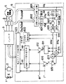
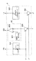
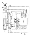
図17は、前記論文に記載されたトルク制御法のブロック線図を示したものである。このブロック線図で、1はバッテリ、2はバッテリ1の電圧検出器、3はPWMインバータでトランジスタなどのスイッチング素子とダイオードとをそれぞれ逆並列接続してなる6つのアームから構成されており、3個の切り替えスイッチとして表すことができる。
4は電流検出器、5は3相の誘導電動機、6はインバータ制御回路である。
【0003】
インバータ制御回路6において、601は電流検出器4により検出された3相電流iu,iv,iwの一次電流ベクトルをd,qの2軸成分i1d,i1qに変換するブロック、602はインバータ制御回路3内のスイッチング状態(Su,Sv,Sw)から一次端子電圧の単位ベクトルを算出するブロック、603,604はその単位ベクトルに電圧検出器2で検出したバッテリ電圧を乗じて一次端子電圧ベクトルの各軸成分V1d,V1qを算出するブロックである。
605,606は、3相電流の一次電流ベクトルの2軸成分i1d,i1qに誘導電動機5の一次巻線抵抗値R1を乗じて電圧値を算出するブロック、607,608は ブロック603,604による一次端子電圧の各軸成分V1d,V1qからブロック605,606による各電圧値を減算するブロック、609,610はブロック607,608の電圧値を積分演算することにより一次磁束ベクトルの各軸成分φ1d,φ1qを算出するブロックである。
【0004】
611は一次磁束ベクトルの各軸成分φ1d,φ1qから一次磁束ベクトルの長さφ1を算出するブロック、612は一次磁束指令値φ1*から一次磁束ベクトルの長さφ1を減算して一次磁束偏差Δφを求めるブロック、613,614はブロック601による一次電流ベクトルの2軸成分i1d,i1qとブロック609,610による一次磁束ベクトルの各軸成分φ1d,φ1qとの積を演算して瞬時トルクTの各軸成分を求めるブロック、615はブロック613,614による各軸成分から瞬時トルクTを求めるブロック、616はトルク指令値T*から瞬時トルクTを減算してトルク偏差ΔTを求めるブロックである。
【0005】
620は、3値ヒステリシスコンパレータで、ブロック616で求めたトルク偏差ΔTに応じて、一次磁束ベクトルと電動機電流のベクトル積として演算された瞬時トルクTとトルク指令値T*とのトルク偏差ΔTが所定の範囲に収まっている場合にはトルクの現状保持指令を表し、所定の範囲を越えている場合には増減指令を表すトルクフラグfTを生成する。
621は、2値ヒステリシスコンパレータで、ブロック612で求めた一次磁束偏差Δφに応じて、ブロック611で演算した一次磁束ベクトルの長さφ1が一次磁束指令値φ1*に対して大きい場合には一次磁束の減少指令を表し、小さい場合には一次磁束の増加指令を表す一次磁束フラグfφを生成する。
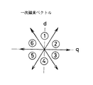
622は、ベクトル位相判定ブロックで、一次磁束ベクトルの位相角θが、図18に示すように、d軸を基準として時計方向の30°,90°,150°,210°,270°,330°の60°毎に仕切られた6つの領域▲1▼〜▲6▼のどの領域に属するかを判定し、その属する領域に応じた位相フラグfθを発生する。
【0006】
623はROMにより構成されたスイッチングテーブルで、トルク応答を最適化した電圧ベクトルを記憶している。ここでは、表1に示す8通りのパターンが記憶されており、トルクフラグfT、一次磁束フラグfφ、位相フラグfθが与えられると、これらのフラグに対応した最適の電圧ベクトルに相当するPWMインバータ3のスイッチングパターンを出力する。
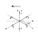
なお、表1における各数値は、図19に数値で示した各電圧ベクトルの方向を示す。
【0007】
【表1】

以上の構成により、インバータ制御回路6は、スイッチングテーブル623が出力する電圧ベクトルとバッテリ電圧と電動機電流および電動機一次巻線抵抗値を用いて一次磁束ベクトルが演算され、それに応じたスイッチングパターンを時々刻々決定してPWMインバータ3に出力する。
一方、実公平6−26079号公報では、与えられたトルク指令値に対して所定の誤差内でトルクが追従するように一次磁束ベクトルの位相の進行、停止を生成するヒステリシスコンパレータのヒステリシス値よりも低いトルク指令値が与えられた場合に、トルク指令値をヒステリシス値に等しい振幅のオンオフパルス列に変換する手段を上記の構成に設けて、電動機の起動や変速の衝撃を低下させている。
【0009】
【発明が解決しようとする課題】
このように、上述の従来技術は、予めROMに記憶された電圧ベクトルを時々刻々の制御フラグ(トルクフラグfT、一次磁束フラグfφ、位相フラグfθ)に応じて読み出す方式であり、PWMインバータのスイッチングの時間間隔は、各ブロックにおける演算の結果として現れるものであるため、電圧ベクトルが次の状態に遷移するまでの時間間隔が不定となり、PWMインバータのスイッチング周波数を所定の値にできない。
このため、例えば、PWMインバータのスイッチング周波数が所定の値に比べて低い場合には、電動機の一次巻線電流に含まれる可聴領域の周波数成分が増加するので、電動機からの耳障りな磁気雑音が発生したり、電動機に流れる電流の歪みが大きくなることによるトルク変動が増大したり、予期しない大電流が電動機に流れることによりインバータの過電流保護機能が作動して運転が円滑に行えないなどの問題がある。
また、電動機内部で発生する逆起電力による影響で、トルク指令値に対する瞬時トルクの平均値が回転数の上昇と共に減少するため、回転数の上昇と共に出力トルクが減少するなどの問題点がある。
また、上記公報では、トルク指令値がヒステリシスコンパレータのヒステリシス値よりも低い場合のみに、パルス幅変調動作を行うだけであるため、これらの問題を解決することができない。
【0010】
本発明は、簡単な構成によってインバータのスイッチング周波数を所望の値に設定し、小型で磁気雑音やトルク変動の少ないインバータ制御装置を提供することを目的とする。
【0011】
【課題を解決するための手段】
本発明の請求項1では、多相誘導電動機に印加される一次端子電圧と多相誘導電動機に流れる一次電流が電圧検出手段と電流検出手段とによってそれぞれ検出されると、これらの検出値から、一次磁束ベクトルおよび瞬時トルク値が磁束ベクトル演算手段とトルク演算手段によりそれぞれ演算され、これらの演算値と一次磁束指令値およびトルク指令値との各偏差および一次磁束ベクトルの位相角に基づいて電圧ベクトルが電圧ベクトル生成手段により生成される。
電圧ベクトルを生成する電圧ベクトル生成手段は、電圧ベクトルの遷移を制御する電圧ベクトル制御手段を備えているため、一次磁束ベクトルおよび瞬時トルク値の演算周期に関係なく、電圧ベクトルの遷移を所望の周期にすることができる。
従って、インバータにおけるスイッチング速度を制限し、スイッチング周波数の上限を制御することによりインバータの発熱を抑えてインバータ冷却装置の小型化を図ることができ、あるいは、電圧ベクトルを決まった時間間隔で強制的に異なる電圧ベクトルに変更することにより、スイッチング周波数を高くすることができ、スイッチング周波数の下限を制限することによって、電動機の磁気雑音やトルク変動の発生を防止することができる。
具体的には、電圧ベクトル制御手段が、電圧ベクトルの変更を所定の期間制限する制限手段を有するため、インバータにおけるスイッチング速度を制限してスイッチング周波数の上限を設定することにより、インバータの発熱を抑えてインバータ冷却装置の小型化を図ることができる。
また、電圧ベクトル制御手段が、生成された電圧ベクトルに対して、任意の時間間隔で異なる電圧ベクトルに操作する操作手段を有するため、電圧ベクトルを決まった時間間隔で強制的に異なる電圧ベクトルに変更することにより、スイッチング周波数を高くすることができる。これにより、スイッチング周波数の低下を防止してスイッチング周波数の下限を制限することによって、所望のスイッチング周波数に設定し、電動機の磁気雑音やトルク変動の発生を防止することができる。
【0014】
請求項2では、多相誘導電動機に印加される一次電圧と多相誘導電動機に流れる一次電流から一次磁束ベクトルおよび瞬時トルク値が演算される。一次磁束指令値と一次磁束ベクトルの一次磁束偏差およびトルク指令値と瞬時トルク値との偏差から制御フラグを決定し、この制御フラグと一次磁束ベクトルの位相角に基づいてインバータに出力する電圧ベクトルが生成される。
制御フラグ群生成手段が、所定の時間が経過する間に制御フラグがオンオフを繰り返すパルスを生成するパルス生成手段を有することにより、所定の時間が経過する度に電圧ベクトルが変更されるので、一次磁束ベクトルおよび瞬時トルク値の演算周期に関係なく、電圧ベクトルの遷移を所望の周期にすることができる。すなわち、パルスの周期により、インバータにおけるスイッチング周波数の上限および下限が制限される。そのスイッチング周波数の上限が制限されることにより、インバータの発熱を抑えてインバータ冷却装置の小型化を図ることができる。また、スイッチング周波数の下限が制限されることにより、電動機の磁気雑音やトルク変動の発生を防止することができる。
【0015】
請求項3では、制御フラグを所定の時間毎に、この所定の時間より短い時間だけ異なる値に変更する変更手段を設けることにより、所定の時間が経過する度に電圧ベクトルが変更されるので、一次磁束ベクトルおよび瞬時トルク値の演算周期に関係なく、電圧ベクトルの遷移を所望の周期にすることができる。すなわち、インバータにおけるスイッチング周波数の下限が制限されることによって、電動機の磁気雑音やトルク変動の発生を防止することができる。
【0016】
請求項4では、パルス生成手段あるいは変更手段により操作された電圧ベクトルにゼロ電圧ベクトルを適用することによって、一次電流の急激な変化を抑制することができるので、電動機のトルク変動の発生を防止することができる。
【0017】
請求項5では、変調波発生手段により所定の振幅で交互に増加と減少を繰り返す変調波を発生し、パルス幅変調手段によりこの変調波に基づき一次磁束偏差またはトルク偏差のパルス幅変調を行う。電動機の起動時または運転時に小さなトルク指令値が与えられた場合、平均的な電圧ベクトルが、従来の制御で実施した時に比べて小さな値として生成されるため、電動機の起動時の衝撃が小さくなる利点が得られる。
【0018】
請求項6では、パルス幅変調する際に、一次磁束偏差またはトルク偏差を比例または比例積分増幅した補償信号をこの変調波に基づきパルス幅変調を行うと、トルク指令値の誤差が少ない制御を実現することができる。
請求項7では、リミッタ手段により変調波を横切るように、一次磁束偏差、トルク偏差またはこれらの補償信号の大きさを制限してパルス幅変調を行うと、変調波の周期内で異なる電圧ベクトルに変更されるので、インバータにおけるスイッチング周波数の下限を制御することが可能になる。
【0019】
請求項8では、符号操作手段により多相誘導電動機の運転象限に基づき一次磁束偏差またはトルク偏差またはこれらの補償信号または変調波のいずれか一つの符号を操作してパルス幅変調を行うことにより、電動機の4象限運転が可能になる。
【0020】
請求項9では、パルス生成手段あるいは変更手段が制御フラグを操作した時間を検出し、この時間に基づいて一次電圧の演算値を実際値に補正する電圧補正手段を備える。これにより、電圧ベクトルを異なる値に操作した場合、電動機のトルクや一次磁束ベクトルの実際の値と演算値との間に誤差が生じても、その誤差分を考慮した電圧ベクトルを出力させることができる。
【0021】
【発明の実施の形態】
次に本発明を図に示す実施例に基づいて説明する。
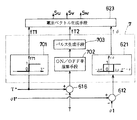
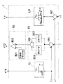
図1は、本発明の第1実施例に係わるインバータ制御装置である。図において、図17の従来技術と同符号にて記したものは従来技術と同構成のものを示すものであるため、説明を省略する。なお、電圧ベクトル生成手段623は、従来技術におけるスイッチングテーブル623と同等のものである。
本発明では、従来技術における3値ヒステリシスコンパレータ620及び2値ヒステリシスコンパレータ621の相当部分に電圧ベクトル制御手段7を設けている。
【0022】
図17の従来技術において、3値ヒステリシスコンパレータ620の出力であるトルクフラグfTは、周知の通り、トルクの増加・減少・現状保持の3状態のいずれかを持つ制御フラグである。このため、第1実施例では、このトルクフラグfTを、誘導電動機5を正転あるいは逆転方向のいずれにトルクを増加させるかを指令する制御フラグとしての第1のトルクフラグfT1と、トルクの増加・現状保持を指令する制御フラグとしての第2のトルクフラグfT2との2つのトルクフラグとして表現している。
表2に従来制御におけるトルクフラグfTとの対応関係を示す。
【0023】
【表2】
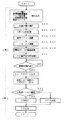
第1実施例に係わる制御フラグ生成手段(電圧ベクトル制御手段)7は、図2に示すように、トルク指令値の極性を判別して電圧ベクトル生成手段623に第1のトルクフラグfT1を出力する極性判別手段701と、トルク偏差からON/OFF率を演算するON/OFF率演算手段702と、ON/OFF率に応じてオンオフパルスを生成して電圧ベクトル生成手段623に第2のトルクフラグfT2を出力するパルス生成手段703と、2値ヒステリシスコンパレータ621を備えている。
【0025】
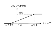
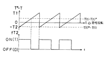
図3は第1実施例におけるON/OFF率演算手段702の動作を示したものである。
第1のトルクフラグfT1は、極性判別手段701により生成され、トルク指令値が正(誘導電動機を正転・力行または逆転・回生で運転する)の場合、正転方向(従来技術における3値ヒステリシスコンパレータ620の出力が「1」に対応する方向)にトルクを増加させる指令fT1=1として電圧ベクトル生成手段623に与えられる。一方、第2のトルクフラグfT2は、ON/OFF率演算手段702により生成され、図3に示すように、トルク偏差がしきい値Δ−T2以下の場合0%を出力し、ΔT1以上の場合は100%を出力し、その中間の場合は0から100%の間の値を出力するように演算し、演算したON/OFF率をパルス生成手段に出力する。図3において、ON/OFF率は、トルク偏差に対して、直線的に変化しているが、直線に限らず、曲線でもよい。
【0026】
パルス生成手段703は、所定の時間t(秒)の間に、
ON時間(秒)=t(秒)×ON/OFF率(%)/100(%)
OFF時間(秒)=t(秒)×(100−ON/OFF率(%)/100(%)
の割合でオンオフを繰り返すパルスを生成する。生成したパルスは第2のトルクフラグfT2として電圧ベクトル生成手段623に与えられる。
なお、上式において、ONは第2のトルクフラグfT2が表2における1に対応し、OFFは第2のトルクフラグfT2が0に対応する。
【0027】
以上の構成によって、第1実施例では、ON/OFF率が0%あるいは100%でない限り、所定の時間t(秒)の間に生成された第2のトルクフラグfT2がオンオフを繰り返すことによって、電圧ベクトルがt(秒)の間に少なくとも2回更新されるため、一次磁束ベクトルおよび瞬時トルクの演算周期に関係なく、電圧ベクトルの遷移を所望の周期にすることができる。従って、PWMインバータ3におけるスイッチ周波数の上限を制限することによりPWMインバータ3の発熱を抑えてインバータ冷却装置の小型化を計ることができ、あるいは、スイッチング周波数の下限を制限することによって、誘導電動機5の磁気雑音やトルク変動の発生を防止することができる。
【0028】
また、表2から分かるとおり、第2のトルクフラグfT2がOFFの時には、電圧ベクトル生成手段623は誘導電動機5の線間電圧をすべて0とする電圧ベクトルであるゼロ電圧ベクトルを選択する。上記実施例のように、第2のトルクフラグfT2をトルク偏差に対応した割合でオンオフ制御することで、トルク偏差の小さい時は、ゼロ電圧ベクトルを多用でき、逆に、トルク偏差の大きい時は、トルクを増加させる電圧ベクトルを多用できる。従って、誘導電動機5の起動時あるいは運転時に小さなトルク指令値が与えられた場合、平均的な電圧ベクトルが、従来の制御で実施した時に比べ小さな値として生成されるため、誘導電動機5の衝撃を小さくできる。また、ゼロ電圧ベクトルを用いることで、一次電流の急激な変化を抑制して、誘導電動機5で発生する急激なトルク変化を抑制できるため、電動機の衝撃を小さくできる。
【0029】
第1の実施例では、制御フラグ群生成手段(電圧ベクトル制御手段)7において、ON/OFF率演算手段702とパルス生成手段703をトルク偏差演算手段616の後段に設け、2値ヒステリシスコンパレータ621を一次磁束偏差演算手段612の後段に設けたが、制御フラグ群生成手段7において、図示を省略するが、ON/OFF率演算手段702とパルス生成手段703を一次磁束偏差演算手段612の後段に設け、3値ヒステリシスコンパレータ620をトルク偏差演算手段616の後段に設けても、電圧ベクトルがt(秒)の間に少なくとも2回更新されるため、一次磁束ベクトルおよび瞬時トルク値の演算周期に関係なく、電圧ベクトルの遷移を所望の周期にすることができる。なお、この構成においては、極性判別手段701は不要である。
【0030】
また、第1の実施例では、制御フラグ群生成手段7において、図示を省略するが、ON/OFF率演算手段702とパルス生成手段703をトルク偏差演算手段616の後段と一次磁束偏差演算手段612の後段にそれぞれ設けても上記実施例と同様の効果がある。
また、第1の実施例では、制御フラグ群生成手段7において、図示を省略するが、ON/OFF率演算手段702に、一次磁束偏差またはトルク偏差またはON/OFF率の上限値および下限値を制限するリミッタ手段を設けることによって、所定の時間t(秒)の間に生成されたトルクフラグfT2が必ずオンオフを繰り返すので、一次磁束偏差またはトルク偏差またはON/OFF率がいかなる値であっても電圧ベクトルがt(秒)の間に少なくも2回更新され、誘導電動機5の磁気雑音やトルク変動をさらに小さくすことができる。
また、第1の実施例では、制御フラグ群生成手段7において、図示を省略するが、極性判別手段701をトルク偏差演算手段616の後段に設けても、上記実施例と同様の効果がある。
【0031】
また、第1の実施例では、制御フラグ群生成手段7において、図4のように、パルス生成手段703で生成したパルスにより、複数の電圧ベクトル生成手段(スイッチングテーブル)623、624から生成したそれぞれの電圧ベクトルを切り替えて、PWMインバータ3に電圧ベクトルを出力する構成も上記実施例と同様の効果がある。
また、第2のトルクフラグfT2のオンオフ周期tは、その時間幅tを変えることにより、任意に設定してもよい。
【0032】
図5に本発明の第2実施例を示す。
第2実施例では、上記図2のON/OFF率演算手段702およびパルス生成手段703に代えて、トルク偏差に対応した割合で第2のトルクフラグfT2をオンオフパルスに変換するパルス幅変調手段80を設けている。パルス幅変調手段80は、変調波を発生する変調波発生手段801と、変調波およびトルク偏差の大小を比較してONまたはOFFの2値を出力する比較手段802を備えている。
【0033】
図6は、第2実施例の動作を詳細に示したものである。
変調波発生手段801は、図6上段に示すように、例えば周期が所定の時間tおよび最小値が−ΔT2、最大値がΔTの三角波を比較手段802に出力する。比較手段は、図6下段に示すように、
変調波の大きさ>トルク偏差 ならば fT2=ON
変調波の大きさ<トルク偏差 ならば fT2=OFF
を出力する。変調波は周期tで増加減少を繰り返すため、比較手段802は周期tでオンオフを繰り返すパルスを出力する。生成したパルスは第2のトルクフラグrfT2として電圧ベクトル生成手段623に与えられる。なお、上記において、ONは第2のトルクフラグfT2が表2における「1」に対応し、OFFは第2のトルクフラグfT2が表2における「0」に対応する。
【0034】
以上の構成によって、第2実施例では第1実施例と同様の効果がある。すなわちインバータ冷却装置の小型化を図ることができ、あるいは誘導電動機5の磁気雑音やトルク変動の発生を防止することができ、あるいは電動機の起動時、運転時における衝撃を小さくできる。
【0035】
第2実施例において、変調波発生手段801の変調波(三角波)の周期tを可変にしてもよい。また、第2実施例では、制御フラグ群生成手段7において、パルス幅変調手段80をトルク偏差演算手段616の後段に設け、2値ヒステリシスコンパレータ621を一次磁束偏差演算手段612の後段に設けたが、制御フラグ群生成手段7において、図示を省略するが、パルス幅変調手段80を一次磁束偏差演算手段612の後段に設け、図17の従来技術に示した3値ヒステリシスコンパレータ620をトルク偏差演算手段616の後段に設けても、上記実施例と同様の効果がある。
また、第2実施例では、制御フラグ群生成手段7において、図示を省略するが、パルス幅変調手段80をトルク偏差演算手段616の後段と一次磁束偏差演算手段612の後段にそれぞれ設けても上記実施例と同様の効果がある。
【0036】
図7に本発明の第3実施例を示す。
第3実施例では、図5に示した第2実施例における制御フラグ群生成手段7において、トルク偏差演算手段616の後段とパルス幅変調手段80の前段との間にトルク偏差を比例積分して補償信号を出力する比例積分手段85を追加した構成となっている。比例積分手段85は、トルク偏差を増幅する比例手段852と、トルク偏差を積分する積分手段853と、各出力を加算して補償信号を出力する加算手段851を備えている。
【0037】
図7に示す構成において、第2のトルクフラグfT2のON時間とOFF時間の割合は、比例積分手段85の出力する補償信号の値に基づいて決定される。補償信号の値を大きくする程ON時間が長くなり、結果としてトルクは増加し、逆に補償信号の値を小さくする程ON時間が短くなり、結果としてトルクは減少する。
【0038】
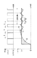
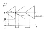
図8は第3実施例の動作を詳細に示したものである。
図の上段は、第2のトルクフラグfT2が所定の周期tでオンオフを繰り返している様子を示した図で、図の下段は、第2のトルクフラグfT2により瞬時トルクが変化している様子を示した図である。
【0039】
積分手段853は、トルク指令値と瞬時トルクの誤差の総和を蓄え出力することで、トルク指令値と瞬時トルクの平均値が一致するように第2のトルクフラグfT2のON時間とOFF時間の割合を逐次操作している。すなわち、図8における斜線A部の面積と斜線B部の面積の総和が等しくなるまで積分を行い続けるので、各面積の総和が等しくなる定常状態cにおいては、積分結果としての補償信号を出力しつつ、トルク指令値と瞬時トルクの平均値が一致している。
【0040】
比例手段852は、トルク指令値T*と瞬時トルクTが素早く一致するように第2のトルクフラグfT2のON時間とOFF時間の割合を逐次操作している。例えば、図8において、トルク指令値T*より瞬時トルクTが小さい区間aにおいては、比例手段852は出力を大きくし、その結果トルクを増加する電圧ベクトルを多用することにより、瞬時トルクはトルク指令値に追従する。また、トルク指令値T*より瞬時トルクTが大きい区間bにおいて、比例手段852は出力を小さくし、その結果トルクを減少するゼロ電圧ベクトルを多用することにより、瞬時トルクはトルク指令値に追従する。このように、比例手段852は、トルク指令値と瞬時トルクの誤差を小さくするように動作する。
なお、上記において、ONは第2のトルクフラグfT2が表2における「1」に対応し、OFFは第2のトルクフラグfT2が表2における「0」に対応する。
【0041】
以上の構成によって、第3実施例では、第2実施例における制御フラグ群生成手段7に、トルク偏差を比例積分して補償信号を出力する比例積分手段85を設けることによって、瞬時トルクの平均値は誘導電動機5の回転数に影響されることなくトルク指令値に一致するため、従来の制御で困難であった高精度のトルク制御を高応答に実現できる。
【0042】
第3実施例において、比例積分手段85は、トルク偏差を増幅する比例手段852のみでもよい。
また、第3実施例では、制御フラグ群生成手段7において、比例積分手段85をトルク偏差演算手段616の後段に設け、2値ヒステリシスコンパレータ621を一次磁束偏差演算手段612の後段に設けたが、図示を省略するが、制御フラグ群生成手段7において、比例積分手段85を一次磁束偏差演算手段612の後段に設け、図17の従来技術に示した3値ヒステリシスコンパレータ620をトルク偏差演算手段616の後段に設けてもよい。
また、第3実施例では、制御フラグ群生成手段7において、図示を省略するが、比例積分手段85をトルク偏差演算手段616の後段と一次磁束偏差演算手段612の後段にそれぞれ設けても上記実施例と同様の効果がある。
【0043】
図9に本発明の第4実施例を示す。
第4実施例では、図5に示した第2実施例における制御フラグ群生成手段7において、極性判別手段701の出力する第1のトルクフラグfT1に応じてトルク偏差の極性を操作する符号操作手段711を追加した構成になっている。
第4実施例に係わる制御フラグ群生成手段7の動作を図10を参照にして説明する。
【0044】
図10はトルク指令値T*の極性が負(誘導電動機を正転・回生または逆転・力行で運転する)の場合のパルス発生手段80の動作を示すものである。
トルク指令値T*の極性が正(誘導電動機を正転・力行または逆転・回生で運転する)の場合、符号操作手段711は、トルク偏差の極性を操作せずそのまま出力する。制御フラグ群生成手段7は、第1実施例で示した動作と同様の動作をするため、説明を省略する。
【0045】
以下、トルク指令値T*の極性が負(誘導電動機を正転・回生または逆転・力行で運転する)の場合のパルス発生手段80の動作を図10を参照に説明する。この場合、符号操作手段711は、トルク偏差の極性を反転して改良トルク偏差T−T*を出力する。
第1のトルクフラグfT1は、極性判別手段701により生成され、逆転方向(3値ヒステリシスコンパレータ620の出力が−1に対応する方向)にトルクを増加させる指令fT1=0として電圧ベクトル生成手段623に与えられる。
【0046】
一方、第2のトルクフラグfT2は、パルス幅変調手段80により生成され図10に示すように、
変調波の大きさ>トルク偏差 ならばfT2=ON
変調波の大きさ<トルク偏差 ならば fT2=OFF
の変調波周期tでオンオフを繰り返すパルスとして電圧ベクトル生成手段623に与えられる。
なお、上記において、ONは第2のトルクフラグfT2が表2における「1」に対応し、OFFは第2のトルクフラグfT2が「0」に対応する。
【0047】
以上の構成によって。第4実施例では、トルク指令値T*の負極性でも運転することができるため、誘導電動機5のすべての運転モード(正・逆転および電動・発電の4象限)における運転が可能になる。従って、すべての運転モードにおいて、第2実施例と同様の効果がある。
符号操作手段711でトルク偏差の極性の反転操作を行う理由は、トルク指令値T*および瞬時トルクTの符号がトルク指令値T*を正極性で運転する時と比べて共に反対の極性となっているためで、上記のように、反転操作を行うことで、正極性で運転する時と同様のオンオフ制御が可能になる。
【0048】
第4実施例は、図示を省略するが、トルク指令値T*の極性に応じてパルス幅変調手段の変調波の極性を反転操作しても上記実施例と同様の効果がある。
また、第4実施例は、図11に示すように、トルク偏差を互いに極性の異なる2つの変調波を用いてパルス幅変調を行うことでfTを与えても上記実施例と同様の効果がある。
また、第3実施例の効果と第4実施例の効果は、それぞれ独立した効果であるため、第3実施例の構成と第4実施例の構成を組み合わせた構成としてもよい。
【0049】
また、第4実施例は、図示を省略するが、符号操作手段711の後段とパルス幅変調手段80の前段の間に比例積分手段85を設け、トルク指令値T*の極性に応じて比例積分手段85の出力である補償信号の極性を操作しても上記実施例と同様の効果がある。
また、図示を省略するが、第1実施例におけるON/OFF率演算手段702と第3実施例における比例積分手段85は、同一の作用をする手段であるため、ON/OFF率演算手段702と比例積分手段85を入れ替えた構成としてもよい。
【0050】
図12に本発明の第5実施例を示す。
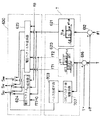
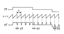
第5実施例では、上記制御フラグ群生成手段7は、図12に示すように、一次磁束偏差から一次磁束ベクトルの大きさの増加/減少を指令する一次磁束フラグfφを出力する2値ヒステリシスコンパレータ621と、トルク偏差から前記瞬時トルク値の増加/減少/現状保持を指令するトルクフラグfTを出力する3値ヒステリシスコンパレータ620と、3値ヒステリシスコンパレータ620の後段に、トルクフラグfTのパルス列に所定の間隔T(例えば、100マイクロ秒)で短い時間幅ΔtのトルクフラグfTとは異なる論理(例えば現状保持を表す論理)のパルスを挿入し改良トルクフラグfT’を出力する変更手段75を備えている。上記変更手段75は、図11に示すように、上記所定の間隔Tを計測するタイマ手段751と、上記短い時間幅Δtのパルスを発生する鋸波加算手段752とを設けている。
【0051】
図13は第5実施例の動作を詳細に示したものである。
3値ヒステリシスコンパレータ620から出力されるトルクフラグfTはトルク偏差に応じてトルクの増加・減少・現状保持の3状態のいずれかを持つ制御フラグであるため、3値ヒステリシスコンパレータ620で得られたトルクフラグfTをそのままスイッチングテーブル(電圧ベクトル生成手段)623に出力すると、PWMインバータ3のスイッチング周波数は、所望の周波数より低くなる場合が十分に考えられる。このため、図13の上段に示すようなパルス列となっているトルクフラグfTに対して、図13の中断に示すように、鋸波加算手段752は、タイマ751による所定の間隔t(例えば100マイクロ秒)でトルクフラグfTのパルス列に、短い時間幅ΔtのトルクフラグfTとは異なる論理(例えば現状保持を表す論理)のパルスを挿入するよう動作することで、図13の下段に示すように、スイッチングテーブル623に出力する改良トルクフラグfT’のパルス列の周波数を増加させて所定の値に規定している。
【0052】
このように、改良トルクフラグfT’が変更される時間を所定の間隔tに設定することで、PWMインバータ3に出力するスイッチング周波数の下限値が規定できる。
従って、制御フラグ群生成手段7において、変更手段75を設けることによって、スイッチング周波数が低くなりすぎることを防止できる。
改良トルクフラグfT’の操作周期tは、タイマ751で計測する時間幅を変えることにより、任意に設定してもよい。
第5実施例では、変更手段75において、タイマ751および鋸波加算手段752を、トルクフラグfTを出力する3値ヒステリシスコンパレータ620の後段に設けたが、一次磁束フラグfφを出力する2値ヒステリシスコンパレータ621の後段に適用して、一次磁束フラグfφを操作するようにしてもよい。
【0053】
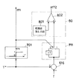
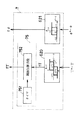
図14に本発明の第6実施例を示す。
第6実施例は、第2実施例から第5実施例を兼ね備えたインバータ制御装置をマイクロプロセッサ9を用いて制御するものである。
図14において、マイクロプロセッサ9は、トルク指令値Tと一次磁束指令値φ1と、バッテリ電圧Eと、モータ電流(Iu,Iv,Iw)と電圧ベクトル(Su,Sv,Sw)を入力して、トルクの増加/減少/現状保持指令であるトルクフラグfTと、一次磁束の増減指令を表す一次磁束フラグfφと、一次磁束の位相角を表す位相フラグfθを出力する。
【0054】
スイッチングテーブル623は、上記各実施例と同様にPWMインバータ3に送り出す電圧ベクトル(Su,Sv,Sw)を記憶しているスイッチングテーブルである。
スイッチングテーブル625は、マイクロプロセッサ9に送り出す電圧ベクトル(Su,Sv,Sw)を記憶しているスイッチングテーブルで、表3に示すように、スイッチングテーブル623に記憶されている電圧ベクトルのゼロ電圧ベクトル(0および7)を消去した内容を記憶している。
【0055】
【表3】
マイクロプロセッサ9の内部構造は、周知のように、プログラムに従って逐次演算を実行するCPUと、アナログ信号をディジタル信号に変換するA/D変換器とディジタル信号をCPUに入力する入力ポートと、ディジタル信号をCPUから出力する出力ポートと、CPUで演算した値を三角波で大小比較を行い、その大小に応じたON/OFFパルスを出力するPWMポートなどから構成される。
【0057】
図15に、第6実施例のインバータ制御装置におけるマイクロプロセッサ9の動作を示す。図中、A区間のルーチンをCPUで繰り返し演算を行い、一方、図中、B区間のルーチンをPWMポートで繰り返し並列演算される様子を示したものである。
図15において、図17の従来制御装置または上記実施例の制御装置と同一の機能のステップについては、同一符号を付して示したので説明を省略し、ここでは、ステップ903の一次端子電圧補正について以下に説明する。
【0058】
従来技術及び上記各実施例で示したインバータ制御装置においては、一次端子電圧は、実際にPWMインバータ3に与えている電圧ベクトル(Su,Sv,Sw)から演算を行う構成になっているが、本実施例のように、マイクロプロセッサ9を使用してインバータ制御を行う場合では、PWMポートを用いて電圧ベクトルを操作しているため、CPU9が一次電流や電圧ベクトルなどの誘導電動機5の状態量を入力してから演算周期T0後に各フラグを出力するまでの間に、途中で電圧ベクトルがゼロベクトルに遷移してしまうため、トルクの実際値と演算値および一次磁束ベクトルの実際値と演算値との間にゼロ電圧ベクトル挿入による誤差が生じる。
そのため、この誤差を補正するためにステップ903において一次端子電圧補正機能を与えている。
【0059】
以下に、ステップ903における一次端子電圧の補正方法を、図16を参照して説明する。
図16の上段はPWMポートの動作を示した図で、三角波と改良トルク偏差(破線)の大小を比較している様子を表している。中段は、上段の比較によって決まるスイッチングテーブル623に出力する第2のトルクフラグfT2の遷移を表している。下段は、第2のトルクフラグfT2がON(トルク増加指令)になっている時間を計測するカウンタの様子を表している。
ここでは、上述の表2に示したとおり、第2トルクフラグfT2がOFF状態の時に、必ずスイッチングテーブル623がゼロ電圧ベクトルを選択することを利用して、CPUの演算周期T0と第2トルクフラグfT2がONになっている時間の割合(duty)を演算し、この割合とスイッチングテーブル625が出力する電圧ベクトル(Su´,Sv´,Sw´)から、
U相端子電圧=E×Su´×duty
V相端子電圧=E×Sv´×duty
W相端子電圧=E×Sw´×duty
により、一次端子電圧の補正を行うように動作する。
【0060】
第6実施例は、トルク偏差をPWMポートに与えてパルス幅変調をする個性として、トルクフラグfTを操作したが、一次磁束変化さをPWMポートに与えてパルス幅変調をする構成として、一次磁束フラグfφを操作するようにしてもよい。
この第6実施例は、第5実施例の変更手段を用いて実施した場合についても同様に適用できる。
【0061】
以上各実施例により詳細に説明したごとく、本発明に係わる誘導電動機のインバータ制御装置によれば、従来の高速トルク方式では困難であったインバータスイッチング周波数の一定化が簡単な装置を追加するだけで可能となるため、インバータ冷却装置を大型にすることなく、また、電動機の磁気騒音やトルク変動を抑制できる。
【図面の簡単な説明】
【図1】本発明に係る誘導電動機のインバータ制御装置を示すブロック線図である。
【図2】本発明の第1実施例の制御フラグ群生成手段を示すブロック線図である。
【図3】本発明の第1実施例のON/OFF率生成手段の動作示すグラフである。
【図4】本発明の第1実施例の制御フラグ群生成手段の変形例を示すブロック線図である。
【図5】本発明の第2実施例のパルス幅変調手段を示すブロック線図である。
【図6】本発明の第2実施例のパルス幅変調手段の動作を示すタイムチャート。
【図7】本発明の第3実施例の比例積分手段を示すブロック線図である。
【図8】本発明の第3実施例の積分手段の動作を示すタイムチャート。
【図9】本発明の第4実施例の符号操作手段を示すブロック線図である。
【図10】本発明の第4実施例の符号操作手段の動作を示すタイムチャート。
【図11】本発明の第4実施例の符号操作手段の変形例の動作を示すタイムチャート。
【図12】本発明の第5実施例の変更手段を示すブロック線図である。
【図13】本発明の第5実施例の変更手段の動作を示すタイムチャート。
【図14】本発明の第6実施例に係る誘導電動機のインバータ制御装置を示すブロック線図である。
【図15】本発明の第6実施例のマイクロプロセッサの動作を示す流れ図である。
【図16】本発明の第6実施例の一次端子電圧補正を示すタイムチャートである。
【図17】従来の誘導電動機のインバータ制御装置を示すブロック線図である。
【図18】誘導電動機の一次磁束ベクトルの位相角θの領域を示す位相分割図である。
【図19】誘導電動機の電圧ベクトルとスイッチングテーブルの数値との関係を示す図。
【符号の説明】
2 電圧検出器(電圧検出手段)
3 PWMインバータ(インバータ)
4 電流検出器(電流検出手段)
5 誘導電動機(多相誘導電動機)
6 インバータ制御回路(インバータ制御装置)
609,610 ブロック(磁束ベクトル演算手段)
612 ブロック(一次磁束偏差演算手段)
615 ブロック(トルク演算手段)
616 ブロック(トルク偏差演算手段)
622 ブロック(位相角演算手段)
623 スイッチングテーブル(電圧ベクトル生成手段)
624 スイッチングテーブル(電圧ベクトル生成手段)
625 スイッチングテーブル(電圧ベクトル生成手段)
7 制御フラグ群生成手段(電圧ベクトル制御手段、制御フラグ群生成手段)
701 極性判定手段
702 ON/OFF率演算手段
703 パルス生成手段(操作手段、パルス生成手段)
711 符号操作手段
75 変更手段
751 タイマ手段
752 鋸波加算手段
80 パルス幅変調手段
801 変調波発生手段
802 比較手段
85 比例積分手段(制限手段、補償手段)
852 比例手段
853 積分手段
9 マイクロプロセッサ(電圧補正手段)
φ1* 一次磁束指令値
T* トルク指令値[0001]
BACKGROUND OF THE INVENTION
The present invention relates to a method for controlling torque vector of an induction motor by controlling a voltage vector of a PWM inverter, and relates to an inverter control device capable of operating with low frequency magnetic noise by operating an inverter switching frequency in a desired band. In addition, the present invention relates to an inverter control device with good torque response.
[0002]
[Prior art]
Conventionally, as a method for controlling torque of an induction motor at high speed, “New High Speed Torque Control Method for Induction Motor Based on Instantaneous Slip Frequency Control” on Vol.
FIG. 17 shows a block diagram of the torque control method described in the paper. In this block diagram, 1 is a battery, 2 is a voltage detector of the
4 is a current detector, 5 is a three-phase induction motor, and 6 is an inverter control circuit.
[0003]
In the
[0004]
[0005]
622 is a vector phase determination block, and the phase angle θ of the primary magnetic flux vector is 30 °, 90 °, 150 °, 210 °, 270 °, 330 ° in the clockwise direction with respect to the d-axis as shown in FIG. It is determined which of the six areas {circle around (1)} to {circle around (6)} divided every 60 °, and a phase flag fθ corresponding to the belonging area is generated.
[0006]
Each numerical value in Table 1 indicates the direction of each voltage vector indicated by the numerical value in FIG.
[0007]
[Table 1]
With the above configuration, the
On the other hand, in Japanese Utility Model Publication No. 6-26079, the hysteresis value of the hysteresis comparator that generates the advance and stop of the phase of the primary magnetic flux vector so that the torque follows the given torque command value within a predetermined error. When a low torque command value is given, means for converting the torque command value into an on / off pulse train having an amplitude equal to the hysteresis value is provided in the above configuration to reduce the start-up of the motor and the impact of the shift.
[0009]
[Problems to be solved by the invention]
As described above, the above-described conventional technique is a method of reading a voltage vector stored in advance in the ROM according to the control flag (torque flag fT, primary magnetic flux flag fφ, phase flag fθ) every moment. Since this time interval appears as a result of calculation in each block, the time interval until the voltage vector transitions to the next state becomes indefinite, and the switching frequency of the PWM inverter cannot be set to a predetermined value.
For this reason, for example, when the switching frequency of the PWM inverter is lower than a predetermined value, the frequency component of the audible region included in the primary winding current of the motor increases, so that annoying magnetic noise from the motor is generated. Problems such as increased torque fluctuation due to large distortion of the current flowing through the motor, and the inverter's overcurrent protection function being activated due to unexpectedly large current flowing through the motor, which prevents smooth operation. There is.
Further, due to the influence of the counter electromotive force generated inside the motor, the average value of the instantaneous torque with respect to the torque command value decreases as the rotational speed increases, and thus there is a problem that the output torque decreases as the rotational speed increases.
Further, in the above publication, since the pulse width modulation operation is only performed when the torque command value is lower than the hysteresis value of the hysteresis comparator, these problems cannot be solved.
[0010]
An object of the present invention is to provide an inverter control device that is small in size and has little magnetic noise and torque fluctuation by setting the switching frequency of an inverter to a desired value with a simple configuration.
[0011]
[Means for Solving the Problems]
The present inventionIn claim 1 ofWhen the primary terminal voltage applied to the multiphase induction motor and the primary current flowing through the multiphase induction motor are detected by the voltage detection means and the current detection means, respectively,,The primary magnetic flux vector and the instantaneous torque value are respectively calculated by the magnetic flux vector calculating means and the torque calculating means, and the voltage vector based on the deviation between these calculated values and the primary magnetic flux command value and the torque command value and the phase angle of the primary magnetic flux vector. Is generated by the voltage vector generating means.
Since the voltage vector generating means for generating the voltage vector includes voltage vector control means for controlling the transition of the voltage vector, the voltage vector transition can be changed to a desired period regardless of the calculation period of the primary magnetic flux vector and the instantaneous torque value. Can be.
Therefore, by limiting the switching speed in the inverter and controlling the upper limit of the switching frequency, the inverter cooling can be suppressed to reduce the size of the inverter cooling device, or the voltage vector can be forced at fixed time intervals. By changing to a different voltage vector, the switching frequency can be increased, and by limiting the lower limit of the switching frequency, it is possible to prevent the occurrence of magnetic noise and torque fluctuation of the motor.
Specifically, since the voltage vector control means has a limiting means for limiting the change of the voltage vector for a predetermined period, the switching speed in the inverter is limited to set the upper limit of the switching frequency, thereby suppressing the heat generation of the inverter. Thus, the inverter cooling device can be downsized.
In addition, since the voltage vector control means has an operation means for operating the generated voltage vector to a different voltage vector at an arbitrary time interval, the voltage vector is forcibly changed to a different voltage vector at a fixed time interval. As a result, the switching frequency can be increased. Thereby, by lowering the switching frequency and limiting the lower limit of the switching frequency, it is possible to set the desired switching frequency and prevent the occurrence of magnetic noise and torque fluctuation of the electric motor.
[0014]
Claim 2The primary magnetic flux is calculated from the primary voltage applied to the multiphase induction motor and the primary current flowing through the multiphase induction motor.vectorAnd instantaneous torquevalueIs calculated. Primary magnetic flux command value and primary magnetic fluxvectorofPrimary magnetic fluxDeviation, torque command value and instantaneous torquevalueControl flag from deviation fromDecisionThen, a voltage vector to be output to the inverter is generated based on the control flag and the phase angle of the primary magnetic flux vector.
A control flag group generating means for generating a pulse generating means for generating a pulse for repeatedly turning on and off the control flag while a predetermined time elapses;HaveBy a given timeButVoltage vector every timeButBecause it is changed, the primary magnetic flux vector and instantaneous torquevalueRegardless of the calculation cycle, the transition of the voltage vector can be set to a desired cycle. That is, the upper limit of the switching frequency in the inverter, depending on the pulse periodandThe lower limit is limitedTheThatSwitchingBy limiting the upper frequency limit,It is possible to reduce the size of the inverter cooling device by suppressing the heat generation of the inverter.The AlsoBy limiting the lower limit of the switching frequency, it is possible to prevent the occurrence of magnetic noise and torque fluctuation of the motor.
[0015]
Claim 3Let's set the control flag every predetermined time,By providing changing means for changing to a different value for a time shorter than the predetermined time, the voltage vector isButBecause it is changed, the primary magnetic flux vector and instantaneous torquevalueRegardless of the calculation cycle, the transition of the voltage vector can be set to a desired cycle. In other words, the lower limit of the switching frequency in the inverter is limited, preventing the occurrence of magnetic noise and torque fluctuations in the motor.To doit can.
[0016]
Claim 4Then, by applying the zero voltage vector to the voltage vector operated by the pulse generating means or changing means, the rapid change of the primary current is suppressed.To doCan prevent motor torque fluctuationsTo doit can.
[0017]
Claim 5Then, the modulated wave generating means generates a modulated wave that repeatedly increases and decreases alternately with a predetermined amplitude, and the pulse width modulating means generates a modulated wave based on the modulated wave.Primary flux deviation or torquePerform pulse width modulation of the deviation. When a small torque command value is given at the time of starting or operating the motor, the average voltage vector is generated as a small value compared to the case where the conventional control is performed, so that the shock at the time of starting the motor is reduced.Benefits.
[0018]
Claim 6Then, when performing pulse width modulation,Primary flux deviation or torqueWhen the compensation signal with proportional or proportional integral amplification of the deviation is subjected to pulse width modulation based on this modulation wave,torqueControl with less command value errorTheRealizationTo doit can.
Claim 7Then, the limiter means to cross the modulated wave, Primary magnetic flux deviation, torqueDeviation ortheseWhen pulse width modulation is performed with the compensation signal size limited, the voltage is changed to a different voltage vector within the period of the modulated wave.InControls the lower limit of switching frequencyCan beThe
[0019]
Claim 8Then, based on the operating quadrant of the multiphase induction motor by the sign operating meansPrimary flux deviation or torqueDeviation orthesePulse width modulation is performed by operating one of the codes of the compensation signal or the modulated waveBy4 quadrant operation of the motorPossibleThe
[0020]
In claim 9Detects the time when the pulse generating means or changing means operates the control flag, and based on this time, the primary voltage is detected.ofCorrecting the calculated value to the actual valueVoltageCorrection means are provided. This manipulated the voltage vector to a different valueIf the motorEven if an error occurs between the actual value of the torque or primary magnetic flux vector and the calculated value, a voltage vector that takes into account the error is output.LetCan.
[0021]
DETAILED DESCRIPTION OF THE INVENTION
Next, the present invention will be described based on embodiments shown in the drawings.
FIG. 1 shows an inverter control apparatus according to a first embodiment of the present invention. In the figure, what is denoted by the same reference numerals as those of the prior art in FIG. The voltage vector generation means 623 is equivalent to the switching table 623 in the prior art.
In the present invention, the voltage vector control means 7 is provided in the corresponding part of the
[0022]
In the prior art of FIG. 17, the torque flag fT that is the output of the
Table 2 shows the correspondence with the torque flag fT in the conventional control.
[0023]
[Table 2]
As shown in FIG. 2, the control flag generation means (voltage vector control means) 7 according to the first embodiment determines the polarity of the torque command value and outputs the first torque flag fT1 to the voltage vector generation means 623. The polarity discriminating means 701, the ON / OFF rate calculating means 702 for calculating the ON / OFF rate from the torque deviation, the ON / OFF pulse is generated according to the ON / OFF rate, and the voltage vector generating means 623 receives the second torque flag fT2. And a
[0025]
FIG. 3 shows the operation of the ON / OFF rate calculating means 702 in the first embodiment.
The first torque flag fT1 is generated by the polarity discriminating means 701, and when the torque command value is positive (the induction motor is operated by normal rotation / power running or reverse rotation / regeneration), the normal rotation direction (three-value hysteresis in the prior art) The output of the
[0026]
The pulse generation means 703 has a predetermined time t (seconds).
ON time (seconds) = t (seconds) × ON / OFF rate (%) / 100 (%)
OFF time (seconds) = t (seconds) × (100−ON / OFF rate (%) / 100 (%)
A pulse that repeats on / off at a rate of is generated. The generated pulse is given to the voltage vector generating means 623 as the second torque flag fT2.
In the above equation, ON corresponds to the second torque flag fT2 corresponding to 1 in Table 2, and OFF corresponds to the second torque flag fT2 corresponding to 0.
[0027]
With the above configuration, in the first embodiment, unless the ON / OFF rate is 0% or 100%, the second torque flag fT2 generated during the predetermined time t (seconds) is repeatedly turned on and off, Since the voltage vector is updated at least twice during t (seconds), the transition of the voltage vector can be set to a desired period regardless of the calculation period of the primary magnetic flux vector and the instantaneous torque. Accordingly, by limiting the upper limit of the switch frequency in the
[0028]
As can be seen from Table 2, when the second torque flag fT2 is OFF, the voltage vector generation means 623 selects a zero voltage vector that is a voltage vector in which all line voltages of the
[0029]
In the first embodiment, in the control flag group generation means (voltage vector control means) 7, an ON / OFF rate calculation means 702 and a pulse generation means 703 are provided in the subsequent stage of the torque deviation calculation means 616 and a
[0030]
In the first embodiment, although not shown in the control flag group generation means 7, the ON / OFF rate calculation means 702 and the pulse generation means 703 are replaced with the subsequent stage of the torque deviation calculation means 616 and the primary magnetic flux deviation calculation means 612. Even if each is provided in the subsequent stage, the same effect as in the above embodiment can be obtained.
In the first embodiment, although not shown in the control flag
In the first embodiment, although not shown in the control flag group generation means 7, even if the polarity determination means 701 is provided in the subsequent stage of the torque deviation calculation means 616, the same effect as in the above embodiment is obtained.
[0031]
In the first embodiment, the control flag
The on / off cycle t of the second torque flag fT2 may be arbitrarily set by changing the time width t.
[0032]
FIG. 5 shows a second embodiment of the present invention.
In the second embodiment, instead of the ON / OFF rate calculating means 702 and the pulse generating means 703 in FIG. 2, the pulse width modulating means 80 for converting the second torque flag fT2 into on / off pulses at a rate corresponding to the torque deviation. Is provided. The pulse
[0033]
FIG. 6 shows the operation of the second embodiment in detail.
As shown in the upper part of FIG. 6, the modulated
If modulation wave size> torque deviation, fT2 = ON
If modulation wave size <torque deviation, fT2 = OFF
Is output. Since the modulated wave repeats increasing and decreasing at the period t, the comparing means 802 outputs a pulse that repeats on and off at the period t. The generated pulse is given to the voltage vector generating means 623 as the second torque flag rfT2. In the above, ON corresponds to the second torque flag fT2 corresponding to “1” in Table 2, and OFF corresponds to the second torque flag fT2 corresponding to “0” in Table 2.
[0034]
With the above configuration, the second embodiment has the same effects as the first embodiment. That is, it is possible to reduce the size of the inverter cooling device, to prevent the
[0035]
In the second embodiment, the period t of the modulated wave (triangular wave) of the modulated wave generating means 801 may be variable. In the second embodiment, in the control flag group generation means 7, the pulse width modulation means 80 is provided in the subsequent stage of the torque deviation calculation means 616, and the
In the second embodiment, although not shown in the control flag group generation means 7, the pulse width modulation means 80 may be provided in the subsequent stage of the torque deviation calculation means 616 and the subsequent stage of the primary magnetic flux deviation calculation means 612. There are the same effects as in the embodiment.
[0036]
FIG. 7 shows a third embodiment of the present invention.
In the third embodiment, in the control flag group generation means 7 in the second embodiment shown in FIG. 5, the torque deviation is proportionally integrated between the subsequent stage of the torque deviation calculation means 616 and the previous stage of the pulse width modulation means 80. A proportional integration means 85 for outputting a compensation signal is added. The
[0037]
In the configuration shown in FIG. 7, the ratio between the ON time and the OFF time of the second torque flag fT2 is determined based on the value of the compensation signal output from the proportional integration means 85. Increasing the value of the compensation signal increases the ON time, resulting in an increase in torque. Conversely, decreasing the value of the compensation signal decreases the ON time, resulting in a decrease in torque.
[0038]
FIG. 8 shows the operation of the third embodiment in detail.
The upper part of the figure shows how the second torque flag fT2 is repeatedly turned on and off at a predetermined period t, and the lower part of the figure shows how the instantaneous torque changes due to the second torque flag fT2. FIG.
[0039]
The integrating means 853 stores and outputs the sum of the errors between the torque command value and the instantaneous torque, so that the ratio between the ON time and the OFF time of the second torque flag fT2 so that the torque command value and the average value of the instantaneous torque coincide with each other. Are operated sequentially. That is, the integration is continued until the sum of the areas of the hatched portion A and the hatched portion B in FIG. 8 becomes equal. Therefore, in the steady state c where the sum of the areas becomes equal, a compensation signal as an integration result is output. However, the torque command value and the average value of the instantaneous torque match.
[0040]
The proportional means 852 sequentially operates the ratio between the ON time and the OFF time of the second torque flag fT2 so that the torque command value T * and the instantaneous torque T quickly coincide with each other. For example, in FIG. 8, in the section a where the instantaneous torque T is smaller than the torque command value T *, the proportional means 852 increases the output, and as a result, the voltage vector that increases the torque is used frequently, so that the instantaneous torque becomes the torque command. Follow the value. Further, in the section b where the instantaneous torque T is larger than the torque command value T *, the
In the above, ON corresponds to the second torque flag fT2 corresponding to “1” in Table 2, and OFF corresponds to the second torque flag fT2 corresponding to “0” in Table 2.
[0041]
With the above configuration, in the third embodiment, the control flag group generation means 7 in the second embodiment is provided with the proportional integration means 85 that proportionally integrates the torque deviation and outputs a compensation signal, so that the average value of the instantaneous torque is obtained. Since it matches the torque command value without being affected by the rotational speed of the
[0042]
In the third embodiment, the proportional integration means 85 may be only the proportional means 852 that amplifies the torque deviation.
Further, in the third embodiment, in the control flag group generation means 7, the proportional integration means 85 is provided after the torque deviation calculation means 616, and the
In the third embodiment, although not shown in the control flag group generation means 7, the proportional integration means 85 may be provided in the subsequent stage of the torque deviation calculation means 616 and the subsequent stage of the primary magnetic flux deviation calculation means 612, respectively. Has the same effect as the example.
[0043]
FIG. 9 shows a fourth embodiment of the present invention.
In the fourth embodiment, in the control flag group generation means 7 in the second embodiment shown in FIG. 5, the sign operation means for manipulating the polarity of the torque deviation according to the first torque flag fT1 output from the polarity determination means 701. 711 is added.
The operation of the control flag group generation means 7 according to the fourth embodiment will be described with reference to FIG.
[0044]
FIG. 10 shows the operation of the pulse generating means 80 when the polarity of the torque command value T * is negative (the induction motor is operated by normal rotation / regeneration or reverse rotation / power running).
When the polarity of the torque command value T * is positive (the induction motor is operated by normal rotation / power running or reverse rotation / regeneration), the sign operating means 711 outputs the torque deviation polarity without operation. Since the control flag group generation means 7 operates in the same manner as the operation shown in the first embodiment, description thereof is omitted.
[0045]
Hereinafter, the operation of the pulse generation means 80 when the polarity of the torque command value T * is negative (the induction motor is operated by forward rotation / regeneration or reverse rotation / power running) will be described with reference to FIG. In this case, the
The first torque flag fT1 is generated by the
[0046]
On the other hand, the second torque flag fT2 is generated by the pulse width modulation means 80, and as shown in FIG.
If modulation wave size> torque deviation, fT2 = ON
If modulation wave size <torque deviation, fT2 = OFF
Is supplied to the voltage vector generation means 623 as a pulse that repeatedly turns on and off at the modulation wave period t.
In the above, ON corresponds to the second torque flag fT2 corresponding to “1” in Table 2, and OFF corresponds to the second torque flag fT2 corresponding to “0”.
[0047]
With the above configuration. In the fourth embodiment, since the operation can be performed with the negative polarity of the torque command value T *, it is possible to operate the
The reason why the sign operation means 711 reverses the polarity of the torque deviation is that the signs of the torque command value T * and the instantaneous torque T are opposite in polarity compared to when the torque command value T * is operated with positive polarity. Therefore, by performing the reversal operation as described above, the same on / off control as when operating with positive polarity can be performed.
[0048]
Although illustration is omitted in the fourth embodiment, the same effect as in the above embodiment can be obtained even if the polarity of the modulation wave of the pulse width modulation means is reversed according to the polarity of the torque command value T *.
In addition, as shown in FIG. 11, the fourth embodiment has the same effect as the above-described embodiment even when fT is given by performing pulse width modulation on the torque deviation using two modulated waves having different polarities. .
Moreover, since the effects of the third embodiment and the effects of the fourth embodiment are independent effects, the configuration of the third embodiment and the configuration of the fourth embodiment may be combined.
[0049]
Although not shown in the fourth embodiment, a proportional integration means 85 is provided between the subsequent stage of the sign operation means 711 and the previous stage of the pulse width modulation means 80, and proportional integration is performed according to the polarity of the torque command value T *. Manipulating the polarity of the compensation signal, which is the output of the
Although not shown in the figure, the ON / OFF rate calculating means 702 in the first embodiment and the proportional integration means 85 in the third embodiment are the means that perform the same operation, and therefore the ON / OFF rate calculating means 702 and The proportional integration means 85 may be replaced.
[0050]
FIG. 12 shows a fifth embodiment of the present invention.
In the fifth embodiment, as shown in FIG. 12, the control flag group generation means 7 is a binary hysteresis comparator that outputs a primary magnetic flux flag fφ for commanding the increase / decrease of the magnitude of the primary magnetic flux vector from the primary magnetic flux deviation. 621, a
[0051]
FIG. 13 shows the operation of the fifth embodiment in detail.
The torque flag fT output from the
[0052]
Thus, the lower limit value of the switching frequency output to the
Therefore, by providing the change means 75 in the control flag group generation means 7, it is possible to prevent the switching frequency from becoming too low.
The operation period t of the improved torque flag fT ′ may be arbitrarily set by changing the time width measured by the
In the fifth embodiment, in the changing means 75, the
[0053]
FIG. 14 shows a sixth embodiment of the present invention.
In the sixth embodiment, the
In FIG. 14, the
[0054]
The switching table 623 is a switching table that stores voltage vectors (Su, Sv, Sw) sent to the
The switching table 625 is a switching table that stores voltage vectors (Su, Sv, Sw) to be sent to the
[0055]
[Table 3]
As is well known, the internal structure of the
[0057]
FIG. 15 shows the operation of the
In FIG. 15, steps having the same functions as those of the conventional control device of FIG. 17 or the control device of the above-described embodiment are denoted by the same reference numerals and description thereof is omitted. Here, the primary terminal voltage correction of
[0058]
In the inverter control apparatus shown in the prior art and each of the above embodiments, the primary terminal voltage is configured to calculate from the voltage vector (Su, Sv, Sw) actually applied to the
Therefore, in order to correct this error, a primary terminal voltage correction function is provided in
[0059]
Hereinafter, a method of correcting the primary terminal voltage in
The upper part of FIG. 16 is a diagram showing the operation of the PWM port, and shows a state in which the magnitude of the triangular wave and the improved torque deviation (broken line) are compared. The middle row represents the transition of the second torque flag fT2 output to the switching table 623 determined by the comparison in the upper row. The lower part shows the state of the counter that measures the time during which the second torque flag fT2 is ON (torque increase command).
Here, as shown in Table 2 above, the CPU uses the fact that the switching table 623 selects the zero voltage vector when the second torque flag fT2 is in the OFF state. The ratio (duty) of the time when fT2 is ON is calculated, and from this ratio and the voltage vector (Su ′, Sv ′, Sw ′) output from the switching table 625,
U-phase terminal voltage = E x Su 'x duty
V-phase terminal voltage = E × Sv ′ × duty
W-phase terminal voltage = E × Sw ′ × duty
Thus, the primary terminal voltage is corrected.
[0060]
In the sixth embodiment, the torque flag fT is manipulated as a characteristic of applying a torque deviation to the PWM port and performing pulse width modulation. The flag fφ may be operated.
The sixth embodiment can be similarly applied to a case where the sixth embodiment is implemented using the changing means of the fifth embodiment.
[0061]
As described in detail in the above embodiments, according to the inverter control device for an induction motor according to the present invention, it is only necessary to add a device that makes it easy to make the inverter switching frequency constant, which is difficult with the conventional high-speed torque method. Therefore, the magnetic noise and torque fluctuation of the electric motor can be suppressed without increasing the size of the inverter cooling device.
[Brief description of the drawings]
FIG. 1 is a block diagram showing an inverter control device for an induction motor according to the present invention.
FIG. 2 is a block diagram showing control flag group generation means according to the first embodiment of the present invention.
FIG. 3 is a graph showing the operation of the ON / OFF rate generation means of the first embodiment of the present invention.
FIG. 4 is a block diagram showing a modification of the control flag group generation means of the first embodiment of the present invention.
FIG. 5 is a block diagram showing pulse width modulation means of a second embodiment of the present invention.
FIG. 6 is a time chart showing the operation of the pulse width modulation means of the second embodiment of the present invention.
FIG. 7 is a block diagram showing proportional integration means of a third embodiment of the present invention.
FIG. 8 is a time chart showing the operation of the integrating means of the third embodiment of the present invention.
FIG. 9 is a block diagram showing sign operation means of a fourth embodiment of the present invention.
FIG. 10 is a time chart showing the operation of the sign operating means of the fourth embodiment of the present invention.
FIG. 11 is a time chart showing the operation of a modification of the sign operating means of the fourth embodiment of the present invention.
FIG. 12 is a block diagram showing changing means of the fifth embodiment of the present invention.
FIG. 13 is a time chart showing the operation of the changing means of the fifth embodiment of the present invention.
FIG. 14 is a block diagram showing an inverter control apparatus for an induction motor according to a sixth embodiment of the present invention.
FIG. 15 is a flowchart showing the operation of the microprocessor according to the sixth embodiment of the present invention.
FIG. 16 is a time chart showing primary terminal voltage correction according to a sixth embodiment of the present invention;
FIG. 17 is a block diagram showing a conventional inverter control device for an induction motor.
FIG. 18 is a phase division diagram showing a region of a phase angle θ of a primary magnetic flux vector of an induction motor.
FIG. 19 is a diagram showing the relationship between the voltage vector of the induction motor and the numerical value of the switching table.
[Explanation of symbols]
2 Voltage detector (voltage detection means)
3 PWM inverter (inverter)
4 Current detector (current detection means)
5 Induction motor (multi-phase induction motor)
6 Inverter control circuit (inverter controller)
609,610 blocks (magnetic flux vector calculation means)
612 blocks (primary magnetic flux deviation calculation means)
615 block (torque calculation means)
616 blocks (torque deviation calculation means)
622 blocks (phase angle calculation means)
623 Switching table (voltage vector generation means)
624 switching table (voltage vector generation means)
625 switching table (voltage vector generation means)
7 Control flag group generation means (voltage vector control means, control flag group generation means)
701 Polarity determination means
702 ON / OFF rate calculation means
703 Pulse generation means (operation means, pulse generation means)
711 Sign operation means
75 Change means
751 Timer means
752 Saw-wave addition means
80 Pulse width modulation means
801 Modulated wave generating means
802 comparison means
85 Proportional integration means (limitation means, compensation means)
852 Proportional means
853 Integration means
9 Microprocessor (voltage correction means)
φ1 * Primary magnetic flux command value
T * Torque command value
Claims (9)
前記多相誘導電動機に印加される一次端子電圧を検出する電圧検出手段と、
前記多相誘導電動機に流れる一次電流を検出する電流検出手段と、
前記一次端子電圧と前記一次電流から一次磁束ベクトルを演算する磁束ベクトル演算手段と、
前記一次端子電圧と前記一次電流から瞬時トルク値を演算するトルク演算手段と、
前記一次磁束指令値と前記一次磁束ベクトルとの偏差および前記トルク指令値と前記瞬時トルク値とのトルク偏差および前記一次磁束ベクトルの位相角に基づき前記インバータより出力する電圧ベクトルを生成する電圧ベクトル生成手段とを備えたインバータ制御装置において、
前記電圧ベクトル生成手段により生成された前記電圧ベクトルの遷移を制御する電圧ベクトル制御手段を備え、
前記電圧ベクトル制御手段は、前記電圧ベクトルの変更を所定の期間制限する制限手段および前記電圧ベクトルを任意の時間間隔で異なる電圧ベクトルに操作する操作手段を有することを特徴とするインバータ制御装置。A device for controlling a primary magnetic flux generated in a stator of a multiphase induction motor operated using an inverter and a torque generated in the multiphase induction motor by a primary magnetic flux command value and a torque command value, respectively.
Voltage detecting means for detecting a primary terminal voltage applied to the multiphase induction motor;
Current detecting means for detecting a primary current flowing in the multiphase induction motor;
Magnetic flux vector computing means for computing a primary magnetic flux vector from the primary terminal voltage and the primary current;
Torque calculating means for calculating an instantaneous torque value from the primary terminal voltage and the primary current;
Voltage vector generation for generating a voltage vector output from the inverter based on a deviation between the primary magnetic flux command value and the primary magnetic flux vector, a torque deviation between the torque command value and the instantaneous torque value, and a phase angle of the primary magnetic flux vector In an inverter control device comprising means,
Voltage vector control means for controlling transition of the voltage vector generated by the voltage vector generation means ,
The inverter control apparatus, wherein the voltage vector control means includes a limiting means for restricting the change of the voltage vector for a predetermined period and an operation means for operating the voltage vector to a different voltage vector at an arbitrary time interval .
前記多相誘導電動機に印加される一次電圧と前記多相誘導電動機に流れる一次電流から一次磁束ベクトルを演算する磁束ベクトル演算手段と、
前記一次磁束ベクトルと前記一次電流から瞬時トルク値を演算するトルク演算手段と、 前記一次磁束指令値と前記一次磁束ベクトルの大きさとの一次磁束偏差を演算する一次磁束偏差演算手段と、
前記トルク指令値と前記瞬時トルク値とのトルク偏差を演算するトルク偏差演算手段と、
前記一次磁束ベクトルの位相角を演算する位相角演算手段と、
前記一次磁束偏差から前記一次磁束ベクトルの大きさの増加/減少を指令する制御フラグおよび前記トルク偏差から前記瞬時トルク値の増加/減少/現状保持を指令する制御フラグ群生成手段と、
前記位相角および前記制御フラグから前記インバータに出力する電圧ベクトルを生成する電圧ベクトル生成手段とを備えたインバータ制御装置において、
前記制御フラグ群生成手段は、所定の時間でオンオフを繰り返すパルスを生成するパルス生成手段を備え、このパルスにより前記制御フラグを決定し、前記パルスのオン時間とオフ時間の割合が前記一次磁束偏差または前記トルク偏差の少なくともいずれかの偏差に対応した割合であることを特徴とするインバータ制御装置。 A device for controlling a primary magnetic flux generated in a stator of a multiphase induction motor operated using an inverter and a torque generated in the multiphase induction motor by a primary magnetic flux command value and a torque command value, respectively.
Magnetic flux vector computing means for computing a primary magnetic flux vector from a primary voltage applied to the multiphase induction motor and a primary current flowing through the multiphase induction motor;
Torque calculating means for calculating an instantaneous torque value from the primary magnetic flux vector and the primary current; primary magnetic flux deviation calculating means for calculating a primary magnetic flux deviation between the primary magnetic flux command value and the magnitude of the primary magnetic flux vector;
Torque deviation calculating means for calculating a torque deviation between the torque command value and the instantaneous torque value;
Phase angle calculating means for calculating the phase angle of the primary magnetic flux vector;
A control flag for instructing an increase / decrease in the magnitude of the primary magnetic flux vector from the primary magnetic flux deviation, and a control flag group generating means for instructing an increase / decrease / maintenance of the instantaneous torque value from the torque deviation;
In an inverter control device comprising voltage vector generation means for generating a voltage vector to be output to the inverter from the phase angle and the control flag,
The control flag group generation means includes pulse generation means for generating a pulse that repeats on and off at a predetermined time, and determines the control flag based on the pulse, and the ratio of the on time and off time of the pulse is the primary magnetic flux deviation. Alternatively, the inverter control device is a ratio corresponding to at least one of the torque deviations .
前記多相誘導電動機に印加される一次電圧と前記多相誘導電動機に流れる一次電流から一次磁束ベクトルを演算する磁束ベクトル演算手段と、
前記一次磁束ベクトルと前記一次電流から瞬時トルク値を演算するトルク演算手段と、 前記一次磁束指令値と前記一次磁束ベクトルの大きさとの一次磁束偏差を演算する一次磁束偏差演算手段と、
前記トルク指令値と前記瞬時トルク値とのトルク偏差を演算するトルク偏差演算手段と、
前記一次磁束ベクトルの位相角を演算する位相角演算手段と、
前記一次磁束偏差から前記一次磁束ベクトルの大きさの増加/減少を指令する制御フラ グおよび前記トルク偏差から前記瞬時トルク値の増加/減少/現状保持を指令する制御フラグ群生成手段と、
前記位相角および前記制御フラグから前記インバータに出力する電圧ベクトルを生成する電圧ベクトル生成手段とを備えたインバータ制御装置において、
所定の時間が経過するごとに、前記制御フラグを前記所定の時間より短い時間異なる値に変更する変更手段を備えたことを特徴とするインバータ制御装置。 A device for controlling a primary magnetic flux generated in a stator of a multiphase induction motor operated using an inverter and a torque generated in the multiphase induction motor by a primary magnetic flux command value and a torque command value, respectively.
Magnetic flux vector computing means for computing a primary magnetic flux vector from a primary voltage applied to the multiphase induction motor and a primary current flowing through the multiphase induction motor;
Torque calculating means for calculating an instantaneous torque value from the primary magnetic flux vector and the primary current; primary magnetic flux deviation calculating means for calculating a primary magnetic flux deviation between the primary magnetic flux command value and the magnitude of the primary magnetic flux vector;
Torque deviation calculating means for calculating a torque deviation between the torque command value and the instantaneous torque value;
Phase angle calculating means for calculating the phase angle of the primary magnetic flux vector;
A control flag group generation means for instructing the control flag and the torque deviation increases / decreases / current retention of the instantaneous torque value commanding an increase / decrease in the magnitude of the primary magnetic flux vector from the primary flux deviation,
In an inverter control device comprising voltage vector generation means for generating a voltage vector to be output to the inverter from the phase angle and the control flag,
Given to every time, it features and be Louis inverter control device further comprising a changing means for changing the control flag in a short time a different value than the predetermined time.
Priority Applications (2)
| Application Number | Priority Date | Filing Date | Title |
|---|---|---|---|
| JP01428796A JP3675014B2 (en) | 1995-06-08 | 1996-01-30 | Inverter control device |
| US08/659,887 US5798628A (en) | 1995-06-08 | 1996-06-07 | Inverter control system which dynamically varies a voltage vector applied to the inverter based on primary flux and torque deviations |
Applications Claiming Priority (3)
| Application Number | Priority Date | Filing Date | Title |
|---|---|---|---|
| JP7-142224 | 1995-06-08 | ||
| JP14222495 | 1995-06-08 | ||
| JP01428796A JP3675014B2 (en) | 1995-06-08 | 1996-01-30 | Inverter control device |
Publications (2)
| Publication Number | Publication Date |
|---|---|
| JPH0956195A JPH0956195A (en) | 1997-02-25 |
| JP3675014B2 true JP3675014B2 (en) | 2005-07-27 |
Family
ID=26350205
Family Applications (1)
| Application Number | Title | Priority Date | Filing Date |
|---|---|---|---|
| JP01428796A Expired - Fee Related JP3675014B2 (en) | 1995-06-08 | 1996-01-30 | Inverter control device |
Country Status (2)
| Country | Link |
|---|---|
| US (1) | US5798628A (en) |
| JP (1) | JP3675014B2 (en) |
Families Citing this family (19)
| Publication number | Priority date | Publication date | Assignee | Title |
|---|---|---|---|---|
| US6014007A (en) * | 1998-09-29 | 2000-01-11 | Allen-Bradley Company Llc | Method and apparatus for starting an AC drive into a rotating motor |
| US6459230B1 (en) | 2001-02-13 | 2002-10-01 | Rockwell Automation Technologies, Inc. | Method and system for measuring a parameter of motor operation |
| JP3636098B2 (en) * | 2001-06-06 | 2005-04-06 | 東芝三菱電機産業システム株式会社 | Power converter control circuit |
| WO2003030348A1 (en) * | 2001-09-29 | 2003-04-10 | Daikin Industries, Ltd. | Phase current detection method, inverter control method, motor control method, and apparatuses used in these methods |
| JP3864308B2 (en) * | 2002-06-12 | 2006-12-27 | 株式会社安川電機 | PWM inverter control method |
| US7304451B2 (en) * | 2004-03-17 | 2007-12-04 | Kabushiki Kaisha Yasakawa Denki | Motor control apparatus and method for generating modulation wave instruction of PWM inverter of the same motor control apparatus |
| US6972534B1 (en) * | 2004-09-03 | 2005-12-06 | General Motors Corporation | Delay compensation for stable current regulation when using variable-delay random PWM switching |
| US7095209B2 (en) * | 2004-09-29 | 2006-08-22 | Rockwell Automation Technologies, Inc. | Method and apparatus to regulate torque provided to loads |
| EP1873002B1 (en) * | 2005-04-01 | 2012-09-12 | Mitsubishi Denki Kabushiki Kaisha | Electric car control device |
| JP4483749B2 (en) | 2005-09-12 | 2010-06-16 | 株式会社デンソー | Control device for power conversion circuit |
| WO2008107992A1 (en) * | 2007-03-08 | 2008-09-12 | Mitsubishi Electric Corporation | Controller of electric vehicle |
| US7821224B2 (en) * | 2008-04-10 | 2010-10-26 | Tesla Motors, Inc. | Voltage estimation feedback of overmodulated signal for an electrical vehicle |
| JP4858597B2 (en) * | 2008-11-28 | 2012-01-18 | 株式会社デンソー | Rotating machine control device and manufacturing method thereof |
| EP2469692B1 (en) * | 2010-12-24 | 2019-06-12 | ABB Research Ltd. | Method for controlling a converter |
| JP5413420B2 (en) * | 2011-08-08 | 2014-02-12 | 株式会社デンソー | Rotating machine control device |
| CN103875177B (en) * | 2012-01-11 | 2016-10-26 | 日本电产株式会社 | Motor controller |
| CN102684592B (en) * | 2012-05-10 | 2014-10-15 | 南京航空航天大学 | Torque and flux linkage control method for permanent synchronous motor |
| JP6030511B2 (en) * | 2013-07-02 | 2016-11-24 | パナソニック株式会社 | Motor control device, generator control device, and motor control method |
| JP6372448B2 (en) * | 2015-08-19 | 2018-08-15 | 株式会社デンソー | Rotating machine control device |
Family Cites Families (10)
| Publication number | Priority date | Publication date | Assignee | Title |
|---|---|---|---|---|
| JPH06101959B2 (en) * | 1987-05-20 | 1994-12-12 | 東洋電機製造株式会社 | Low noise driving method for induction motor |
| JP2821679B2 (en) * | 1988-07-19 | 1998-11-05 | 株式会社日立製作所 | Method and apparatus for generating gate signal of PWM inverter, PWM inverter apparatus |
| JPH02193587A (en) * | 1988-10-28 | 1990-07-31 | Toyo Electric Mfg Co Ltd | Momentary current control system for induction motor |
| JP2954333B2 (en) * | 1990-11-28 | 1999-09-27 | 株式会社日立製作所 | AC motor variable speed system |
| US5083039B1 (en) * | 1991-02-01 | 1999-11-16 | Zond Energy Systems Inc | Variable speed wind turbine |
| CA2101796C (en) * | 1992-07-21 | 1996-10-01 | Tetsuo Yamada | Vector control apparatus for induction motor |
| US5166593A (en) * | 1991-10-02 | 1992-11-24 | General Electric Company | Closed-loop torque feedback for a universal field-oriented controller |
| GB2261966B (en) * | 1991-11-30 | 1995-11-08 | Toshiba Kk | Driving control apparatus for induction motor |
| JP2760706B2 (en) * | 1992-07-08 | 1998-06-04 | 日立建機株式会社 | Hydraulic construction machine torque control device |
| JPH06351292A (en) * | 1993-06-07 | 1994-12-22 | Sharp Corp | Controller for induction motor |
-
1996
- 1996-01-30 JP JP01428796A patent/JP3675014B2/en not_active Expired - Fee Related
- 1996-06-07 US US08/659,887 patent/US5798628A/en not_active Expired - Fee Related
Also Published As
| Publication number | Publication date |
|---|---|
| US5798628A (en) | 1998-08-25 |
| JPH0956195A (en) | 1997-02-25 |
Similar Documents
| Publication | Publication Date | Title |
|---|---|---|
| JP3675014B2 (en) | Inverter control device | |
| JP3396440B2 (en) | Control device for synchronous motor | |
| US8285451B2 (en) | Method and apparatus for controlling electric power steering system | |
| US8373380B2 (en) | Device and method for controlling alternating-current motor | |
| US5247237A (en) | Control device of induction motor | |
| US6307336B1 (en) | Closed loop control of PWM duty cycle | |
| JPH02219498A (en) | Current controller of inverter | |
| US6504329B2 (en) | Apparatus and method for controlling permanent magnet electric machines | |
| TW200924366A (en) | Matrix converter | |
| JPH11299297A (en) | Controller for permanent magnet synchronous motor | |
| JP2019193445A (en) | Motor drive device | |
| JPH1023756A (en) | Voltage inverter device and method for controlling it | |
| JP5204463B2 (en) | Motor control device | |
| JP3678558B2 (en) | Control device for permanent magnet type synchronous motor | |
| JP3677804B2 (en) | Inverter control device | |
| JP2017127046A (en) | Power converter control device | |
| JP2009284598A (en) | Controller for alternating-current motors | |
| CN112567620B (en) | Inverter device | |
| JPH0517800B2 (en) | ||
| JP3933348B2 (en) | Control device for embedded magnet type synchronous motor | |
| JP2003111428A (en) | Inverter controlled engine generator | |
| JP3287186B2 (en) | PWM control inverter device and PWM control method | |
| JP2006109541A (en) | Controller for power converter | |
| JP5475534B2 (en) | Control device for voltage source inverter | |
| JP2682657B2 (en) | Inverter current controller |
Legal Events
| Date | Code | Title | Description |
|---|---|---|---|
| A131 | Notification of reasons for refusal |
Free format text: JAPANESE INTERMEDIATE CODE: A131 Effective date: 20040706 |
|
| A521 | Request for written amendment filed |
Free format text: JAPANESE INTERMEDIATE CODE: A523 Effective date: 20040903 |
|
| TRDD | Decision of grant or rejection written | ||
| A01 | Written decision to grant a patent or to grant a registration (utility model) |
Free format text: JAPANESE INTERMEDIATE CODE: A01 Effective date: 20050412 |
|
| A61 | First payment of annual fees (during grant procedure) |
Free format text: JAPANESE INTERMEDIATE CODE: A61 Effective date: 20050425 |
|
| R150 | Certificate of patent or registration of utility model |
Free format text: JAPANESE INTERMEDIATE CODE: R150 |
|
| FPAY | Renewal fee payment (event date is renewal date of database) |
Free format text: PAYMENT UNTIL: 20080513 Year of fee payment: 3 |
|
| FPAY | Renewal fee payment (event date is renewal date of database) |
Free format text: PAYMENT UNTIL: 20110513 Year of fee payment: 6 |
|
| LAPS | Cancellation because of no payment of annual fees |