EP1203202B1 - Enhancing voltmeter functionality - Google Patents
Enhancing voltmeter functionality Download PDFInfo
- Publication number
- EP1203202B1 EP1203202B1 EP00948813A EP00948813A EP1203202B1 EP 1203202 B1 EP1203202 B1 EP 1203202B1 EP 00948813 A EP00948813 A EP 00948813A EP 00948813 A EP00948813 A EP 00948813A EP 1203202 B1 EP1203202 B1 EP 1203202B1
- Authority
- EP
- European Patent Office
- Prior art keywords
- voltmeter
- load
- test
- circuit
- leads
- Prior art date
- Legal status (The legal status is an assumption and is not a legal conclusion. Google has not performed a legal analysis and makes no representation as to the accuracy of the status listed.)
- Expired - Lifetime
Links
Images


Classifications
-
- G—PHYSICS
- G01—MEASURING; TESTING
- G01R—MEASURING ELECTRIC VARIABLES; MEASURING MAGNETIC VARIABLES
- G01R15/00—Details of measuring arrangements of the types provided for in groups G01R17/00 - G01R29/00, G01R33/00 - G01R33/26 or G01R35/00
- G01R15/12—Circuits for multi-testers, i.e. multimeters, e.g. for measuring voltage, current, or impedance at will
- G01R15/125—Circuits for multi-testers, i.e. multimeters, e.g. for measuring voltage, current, or impedance at will for digital multimeters
-
- G—PHYSICS
- G01—MEASURING; TESTING
- G01R—MEASURING ELECTRIC VARIABLES; MEASURING MAGNETIC VARIABLES
- G01R31/00—Arrangements for testing electric properties; Arrangements for locating electric faults; Arrangements for electrical testing characterised by what is being tested not provided for elsewhere
- G01R31/50—Testing of electric apparatus, lines, cables or components for short-circuits, continuity, leakage current or incorrect line connections
-
- G—PHYSICS
- G01—MEASURING; TESTING
- G01R—MEASURING ELECTRIC VARIABLES; MEASURING MAGNETIC VARIABLES
- G01R1/00—Details of instruments or arrangements of the types included in groups G01R5/00 - G01R13/00 and G01R31/00
- G01R1/36—Overload-protection arrangements or circuits for electric measuring instruments
-
- G—PHYSICS
- G01—MEASURING; TESTING
- G01R—MEASURING ELECTRIC VARIABLES; MEASURING MAGNETIC VARIABLES
- G01R31/00—Arrangements for testing electric properties; Arrangements for locating electric faults; Arrangements for electrical testing characterised by what is being tested not provided for elsewhere
- G01R31/005—Testing of electric installations on transport means
- G01R31/006—Testing of electric installations on transport means on road vehicles, e.g. automobiles or trucks
Definitions
- the invention relates to enhancing voltmeter functionality, and more particularly, enhancing voltmeter functionality for isolating faults in electrical circuitry.
- Modem vehicles systems incorporate digital (computer) diagnostic systems that can detect many circuit faults in electrical components and systems (e.g., on vehicles). But such systems typically cannot detect all possible circuit faults, for example, high resistance faults caused by corrosion. Moreover, electrical troubleshooting on vehicles and other systems can be time-consuming, labor-intensive, costly, and often ineffective, especially if a component must be disconnected and/or removed for testing circuit continuity.
- circuit faults in wiring and connectors result from abuse, exposure, wear, and normal use. Failures in circuit wiring typically are caused by a change in circuit resistance and fall into one of three categories - an open circuit, a short-to-ground, or a high resistance (e.g., due to corrosion). Other faults, such as a circuit short to another circuit, can be more obvious because they typically show signs of failure that are easier to discern.
- Apparatus typically used to detect electrical faults include ohmmeters, ammeters, and voltmeters.
- the voltmeter measures voltage (potential difference) at any open in a functional circuit, or voltage drop across a resistance with the circuit intact and operating, which is usually safer and more effective, respectively, tan using the ammeter or the ohmmeter. This is because the ammeter must complete a circuit to obtain a reading and the ohmmeter must have all circuit voltage removed and the circuit completely isolated.
- a typical voltmeter can, in some circumstances, be used to locate faults, such as those described above. Simply connecting and turning on the voltmeter, however, may be insufficient or inadequate to solve the problem, and require a time consuming effort to reach an incomplete conclusion. For best results the circuit must be active or energized to detect faults, which requires the circuit to be intact and the load to be installed. Further, to prevent corrosive faults from occurring, if the manufacturer intentionally designs wiring and component terminals not to be externally accessible without the component being removed, performing dynamic circuit tests with typical voltmeter leads can be impossible.
- US 2, 432,013 describes the operation of systems of electrolytic cells operating on direct current, and particularly the location of ground faults in such systems by periodically measuring the resistance between the electrolytic cell, DC circuit and ground, and measuring the voltage at a selected point between the cell circuit and ground. The degree and location of the current leakage is determined from the results of these periodic measurements.
- US 2,785,378 describes an electrical measuring system, for the measurement of the voltage-current characteristics of electrical circuits or apparatus.
- US 4,777,430 describes a circuit for measuring the effective series resistance and Q-factor of a capacitive device that has an operational amplifier with an input to which a source of AC input voltage is applied. A feedback circuit is connected between input and output of the amplifier.
- embodiments of the invention feature circuitry for dynamic testing of a circuit under load.
- the circuitry includes a test load adapted to be coupled between inputs of a voltmeter, and a switch adapted to short circuit test leads of the voltmeter through the test load.
- Embodiments of the invention feature enhanced voltmeter test load circuitry having a test load that can be coupled to or decoupled from the test leads of a voltmeter.
- the embodiments can be used to help identify the location and type of faults, such as a short-to-ground, an open circuit, and a high (e.g., corrosive) resistance, in a circuit under test.
- a fuse or circuit breaker can be provided with the enhanced voltmeter test load circuitry for safety reasons.
- the circuitry can be located within a voltmeter or test leads of a voltmeter, or portions of the circuitry can be located in both.
- the circuitry can be used systematically in locating and identifying the fault from voltage readings at the location of a removed component or a blown fuse or circuit breaker in the circuit under test. Voltage drop readings are obtained at various points in the circuit under test with the test load both coupled and decoupled between (or effectively coupled between) the test leads. A negative or black test lead can be moved to a convenient machine ground during the test and the test can be repeated to confirm the location of the fault. A change in reading can indicate the fault is on the ground side of the circuit under test while no change can indicate the fault is on the positive side of the circuit under test. Conventional test leads can be used if the load circuitry is incorporated or integrated in the voltmeter or if the load circuitry has a separate coupling or connection to the voltmeter inputs.
- embodiments of the invention provide the ability to make a confident and conclusive decision about the type and general location of the electrical fault from component connections, with only two voltmeter readings. No circuit disassembly is required to determine the type of fault, and the user/technician is able to avoid the use of meters less safe than the voltmeter to quantify resistance and current disposition.
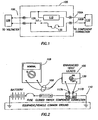
- Fig. 1 shows enhanced voltmeter test load circuitry 100 that includes load circuitry 105 adaptable to any digital voltmeter 108, in accordance with an embodiment of the invention.
- the enhanced voltmeter test load circuitry 100 couples to a "positive" input test lead 100A (e.g. a ''red'' test lead) and a "negative" input test lead 100B (e.g., a "black” test lead).
- the load circuitry 105 adds to the functionality of the voltmeter 108 by allowing a user/technician systematically to identify the type and location of a voltage drop caused by a fault in a circuit under test (CUT) 110.
- CUT circuit under test
- the enhanced voltmeter test load circuitry 100 can help reduce or eliminate the need for additional tests or circuit modification to isolate the circuit fault by enabling dynamic circuit tests to be performed with a circuit component of the CUT 110 removed.
- the load circuitry 105 is coupled to the leads 100A and 100B.
- the load circuitry 105 includes a test load 115, for example, a load, resistor, resistive load, emulated resistive load, and the like of known resistance that can couple across the leads 100A and 100B.
- Other non-limiting possibilities for the test load include transistors, diodes, resistive networks, and the like, as bulk or integrated circuits.
- the test load 115 can be any component or circuit capable of presenting the same or similar load to the CUT 110 as the removed component (i.e., it produces a similar voltage drop).
- the resistance or resistive load value of the test load 115 may be determined, in non-limiting fashion, by taking an average of resistance or resistive load values of components present in systems for which the enhanced voltmeter test load circuitry 100 will be used. This value will change in various embodiments of the invention, as will be appreciated by those skilled in the art. For example, in another embodiment, the value could be the same as that of the component having the highest resistive load value among such system components.
- the typical resistive loads of components in a given system incorporating the CUT 110 will be known, and the user/technician can manually adjust or switch (or activate an automatic adjustment of) the resistive load value of the test load 115 correspondingly at the load circuitry 105 or at the voltmeter 108.
- the adjustment in value of the test load 115 could be automated using knowledge of the maximum current allowed for the CUT 110.
- the resistive load value of the test load 115 is adapted to drop an equivalent voltage drop to the removed component of the CUT 110.
- the test load 115 is in effect an artificial load for the removed component from the CUT 110.
- the load circuitry 105 and the test load 115 thus extend the functionality of the voltmeter 108.
- the load circuitry 105 also includes a switch 130 (termed an "ETL" switch, which can be a push button or other type of switch) and preferably includes, for safety reasons, a fuse or circuit breaker 135 or equivalent (referred to hereinafter simply as the fuse 135).
- the fuse 135 limits the maximum current that can be pulled by the test load 115, ensuring that maximum current during test will remain safely below the maximum allowable for circuits such as the CUT 110.
- the current rating of the fuse 135 is of a value appropriate for this purpose. It is possible that the type or rating of the fuse 135 could vary with application to the particular CUT 110.
- a switch could be provided (not shown) to adjust the rating of the fuse 135 (e.g., by switching between different fuses or circuit breakers) to the particular resistive load of the test load 115 to accommodate the maximum current of the CUT 110.
- the switch 130 and the fuse 135 can be located on either the positive test lead 100Aside or the negative test lead 100B-side of the test load 115.
- a variety of other configurations for the load circuitry 105 can be envisioned.
- the load circuitry 105 instead could be integrated within the test leads 100A and 100B or incorporated as circuitry resident in the voltmeter 108 for use with conventional or other test leads, as will be discussed below.
- Conventional test leads that can be directly coupled to the CUT 110 for testing the CUT 110 can also be used with (i.e., coupled to) the load circuitry 105 if the load circuitry 105 has a separate coupling or connection to the inputs of the voltmeter 108.
- the resistance value of the test load 115 will of necessity be low enough so as to make it possible to detect relatively small resistance faults, and be large enough so as to limit the current through the test load 115 and the CUT 110 to a value below (or well below) the maximum allowable system current through the CUT 110.
- the value chosen for the test load 115 should be as near to the average resistance value(s) of any or all load components that may reside in the CUT 110.
- the test load may have a value designed to work with a 12 volt CUT like the CUT 110 having resistive components typically between approximately 5 ⁇ _and 300 ⁇ (or double that for a 24 volt CUT).
- test load 115 may be required to perform a dynamic test, replacing a coil load of approximately 2000 ⁇ .
- test load 115 values are possible depending on parameters or characteristics of the CUT 110, as will be appreciated by those skilled in the art.
- the resistance or resistive load value of the test load 115 can be variable and adjustable (e.g., between the above values). This can be accomplished with a variable resistor, a potentiometer, or a total resistance chosen from a sequence of series connected or parallel connected resistors of known resistance making up the test load 115, whether integrated in the voltmeter 108 or not
- Other configurations that produce variable resistive load are possible, as will be appreciated by those skilled in the art. These other configurations are included within the scope and spirit of the present invention.
- the total resistive load value can be adjusted manually by a switch (not shown) or a slide or rotating contact, or the like (not shown) at the load circuitry 105 or at the voltmeter 108 (e.g., if the circuitry 105 were contained within the voltmeter 108), as will be appreciated by those skilled in the art.
- the resistive load value can be adjusted and set automatically at the circuitry or under control of the voltmeter (e.g., if the circuitry 105 were contained within the voltmeter 108).
- the total resistance could be set by first starting with the highest resistive load possible and then, if necessary, manually or controllably stepping down in or adjusting (or setting the) value until the highest voltmeter 108 on-scale voltage reading were obtained with a safe current level for the CUT 110 while using the voltmeter 108 as described herein.
- the value of the test load can be set manually, automatically, or both.
- the test load 115 can be switchably coupled (i.e., "on/off' switched between switchable states) into the CUT 110.
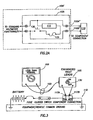
- the test load 115 can be coupled to the CUT 110 via the leads 100A and 100B typically after removal from the CUT 110 of a component (not shown), as illustrated in Fig. 2.
- Contact can be made with the leads 100A and 100B, respectively, to terminals 117A and 117B of the CUT 110 that usually couple to the component before its removal.
- the test load 115 can be coupled to the CUT. 110 (the terminals 117A and 117B are not shown in Fig.
- a voltmeter 108' is illustrated that includes the circuitry 105.
- the voltmeter 108' is like the voltmeter 108 except that the additional functionality available with the circuitry 105 as described herein is included within the voltmeter package.
- the switch 130 With the switch 130 in the load circuitry 105 turned “on” (i.e., closed), the switch 130 completes (in the sense of completing a circuit) the CUT 110 instead of the circuit component.
- the switch 130 short circuits the leads 100A and 100B of the voltmeter 108 (or short circuits the leads 10A" and 100B" of the voltmeter 108') for the purpose of completing the CUT 110 to make a dynamic test of the CUT 110 under load.
- the test load 115 can be electrically decoupled from the leads 100A and 100B (or the leads 100A" and 100B" of the voltmeter 108') and the CUT 110 by turning “off' (i.e., by opening) the switch 130 (see, e.g., Figs. 1, 2, and 2A).
- the switch 130 can be located directly in one of the leads 100A or 100B or in the lead handle of one of these leads. This is shown in Fig. 2B as lead 100A'(e.g., a "positive" lead like the lead 100A) having lead handle 100C' in which the switch 130' (like the switch 130) is located.
- lead 100A' will be, for example, a three-wire lead, one wire being the usual lead wire and the other two wires coupling the switch 130' to circuitry 105' (like the remainder of the circuitry 105), as will be appreciated by those skilled in the art.
- the switch 130' is easily accessible by a finger or thumb of the user/technician.
- the (e.g., three-wire) lead 100A' can be used with a voltmeter 108".
- the voltmeter 108" includes load circuitry 105", which is like the load circuitry 105' except that the load circuitry 105" is incorporated within the voltmeter 108" much like the load circuitry 105 is incorporated within the voltmeter 108'.
- the switch 130' is located in the lead handle 100C' of the lead 100A' for ease of accessibility.
- the conventional lead 100B" is used with the voltmeter 108".
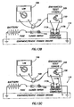
- a nominal standard voltage reading (e.g., system voltage from a circuit battery or other power source) is expected with the voltmeter 108, as shown in Fig. 2.
- a nominal or nearly nominal (i.e., slightly less than) standard voltage reading is expected across the load 115 that completes the CUT 110 without any adjustment in the location or settings of the voltmeter 108.
- the nominal or nearly nominal voltage drop value is obtained in the latter situation from the series combination of the test load 115 and the negligible circuit resistance being tested under load. This difference between a static voltage test and a dynamic voltage drop test is one of the primary improvements of embodiments of the invention over existing circuit troubleshooting systems..
- the operation and analysis of the results obtained when testing the CUT 110 for circuit faults assumes that the sole load in the CUT 110 is the test load 115, as discussed above. Then, a voltage drop across the test load 115 far below an expected voltage drop (e.g., well or substantially below the expected system voltage) indicates that an undesired high resistance fault exists somewhere in the CUT 110.
- the typical types of faults detected with embodiments of the present invention include resistance-based faults, such as a short-to-ground (short circuit or short), a high resistance (e.g., due to corrosion), or an open circuit (e.g., a blown fuse, an electrical conductor breaks, and the like). A variety of other types of faults may be detectable as well.
- Careful manipulation of the meter leads 100A and 100B (or the leads 110A'/100B or the leads 100A"/100B" as described above) in a specified manner will enable the user/technician to determine if the fault is "in front of' (i.e., before) or "behind” (i.e., after) the location of the removed component in the CUT 110 relative to the ground of the CUT 110. This will be discussed in more detail below.
- test leads 100A and 100B or the voltmeter 108 or the load circuitry 105 is understood to include an implied reference to the test leads 100A', 100B', 100A", and 100B" and their respective voltmeters 108' and 108" (and the load circuitry 105' and 105").
- a flow chart can guide a user/technician through a prescribed troubleshooting process that provides the steps to be followed and details the meaning of the results of each test. This can simplify fault troubleshooting and expand the capabilities of any voltmeter 108 by allowing circuit systems like the CUT 110 to be tested dynamically under load using voltage conditions and readings exclusively to identify and locate the fault, such as resistance, short or open circuit fault problems.
- the use of the enhanced voltmeter test load circuitry 100 obviate, in many cases, the need for either an ohmmeter or ammeter to reach a troubleshooting conclusion by using instead voltage readings to locate resistance faults and confirm current flow.
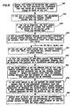
- FIG. 4 An exemplary flow chart of such a process or method is shown in Fig. 4, in accordance with an embodiment of the invention.
- the user/technician determines, at block 200, whether the failed circuit contains a short-to-ground or a wiring problem by determining if there is a blown fuse or open circuit breaker in the CUT 110. Such an event is likely to occur if there is a short-to-ground.
- the enhanced voltmeter test load circuitry 100 (e.g., using the test leads 100A and 100B) can be installed, with the component removed, from the voltmeter 108 and coupled, at block 210, to the terminals 119A and 119B, replacing the fuse or breaker in the suspect CUT 110.
- the threat of further short circuit or harm is unlikely because of the input resistance (or impedance), which is typically greater than 50,000 Ohms per volt (>50k ⁇ /V), of the voltmeter 108 (e.g., when the switch 130 is off) and because of the test load 115 and the fuse 135, which are coupled to the leads (e.g., the leads 100A and 100B) (e.g., when the switch 130 is on).
- the voltage reading, at block 220 would be a "ghost" reading. This is because there is not a complete circuit since the ground of the CUT 110 has been removed by removal of the component. If the user/technician turns the switch 130 on, a ghost reading would again be obtained. The ghost reading is due to the peculiar characteristics of a digital voltmeter. Such a voltmeter is sensitive enough that it would float (i.e., detect and read a fluctuating static or earth-magnetic voltage with the test leads, e.g., the leads 100A and 100B isolated from each other while on a millivolt range).
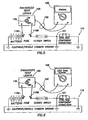
- the voltmeter 108 would read the nominal system voltage due to the presence of an inadvertent circuit ground caused by the fault With the voltmeter 108 set to acquire the voltage across the open fuse or breaker position of the CUT 110, as shown in Fig. 6, if the switch 130 is turned on and a short circuit exists, at block 240, the voltmeter 108 would indicate nearly the nominal system voltage or slightly less. A reading significantly lower than the nominal system voltage indicates the presence of the short 121 with some added (e.g., corrosive) resistance.
- the user/technician would leave the leads 100A and 100B installed in the open fuse or breaker position of the CUT 110, and begin to isolate circuit segments from ground by using standard disconnection methods (i.e., disconnection of connectors, switches, terminals, and the like).
- disconnection methods i.e., disconnection of connectors, switches, terminals, and the like.
- the voltage reading either would remain substantially constant (e.g., at or near the nominal system voltage) or change to a ghost reading, as shown in Fig. 7.
- the ghost reading again indicates a loss of ground (in this case, the loss of the inadvertent ground caused by the short-to-ground 121), and provides the ability for the user/technician to identify the segment or section of the CUT 110 being tested that includes the short 121.
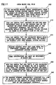
- circuit fault is not a short-to-ground (as indicated by the circuit fuse or circuit breaker remaining intact), reference is made to Fig. 8.
- CUT 110 component connections 117A and 117B as reference, CUT faults caused by an open circuit or unintentional high resistance can occur only in the wiring either on the positive side (i.e., in front of) or on the negative side (i.e., behind) the component connections 117A and 117B.
- the user/technician will repeat the initial test (at block 320 discussed below) after removing the negative lead 100B to a convenient machine ground (see blocks 350 and 430 (Fig. 11) discussed below). This action has the effect of removing the ground portion of the CUT 110 (e.g., the wiring "behind" the component connection 117B), thereby allowing the circuit to be isolated to a degree. This further affords an opportunity to use a process of elimination to locate the fault relative to the component connections 117A and 117B.
- the abnormal reading e.g., a ghost reading in the case of an open circuit, or a substantially lower than normal reading in the case of a high resistance
- the fault must be located in the positive side of the CUT 110. If the reading changes to a "normal" reading under the same circumstances, then the fault must be in the negative side of the CUT 110.
- the user/technician compares the reading taken initially with the reading taken after removing the lead 100B to a machine ground. It is this expected change in the reading of the voltmeter 108 that differentiates embodiments of the invention from any other existing device.
- the load circuitry 105 essentially mimics the electrical effect of the CUT 110 load (i.e., the component to be removed), thereby allowing a dynamic voltage drop reading rather than simply a static voltage reading.
- the user/technician couples, at block 300, the test leads 100A and 100B of the voltmeter 108 on the CUT 110, replacing the component normally resident in the CUT 110.
- the voltmeter 108 would indicate nominal system voltage with the switch 130 turned off. If the CUT 110 is complete, as indicated by the presence of a nominal voltage reading, the user/technician then activates, at block 320, the enhanced voltmeter test load circuitry 100 by closing the switch 130 to couple in the test load 115.
- the voltmeter 108 reading remains substantially constant at the nominal system voltage or drops only slightly, then the user/technician can assume that no additional undesired resistance exists in the CUT 110 and the component itself that was removed probably has failed. This is because any added resistance (e.g. if there were no open circuit) in the CUT 110 would cause the voltmeter 108 reading to drop significantly due to the added voltage drop, according to Kirchoff's Law.
- the CUT 110 has an open circuit 138, as shown in Figs. 9A and 9B, with the switch 130 turned off (or on), the voltmeter 108 would indicate a ghost reading.
- the user/technician can remove, at block 350, the negative input test lead 100B to the voltmeter 108 from the component connection terminal 117B and couple the lead 100B to a convenient machine ground 140 (see Figs. 10A and 10B, corresponding to Figs. 9A and 9B, respectively).
- This action has the effect of removing the ground portion of the circuit from the test and allows the test to use the process of elimination to isolate the location of the fault.
- the open circuit 138 is on the ground side of the terminal 117B and the switch 130 is off (Fig. 10A)
- the reading on the voltmeter 108 would be the nominal system voltage.
- the reading would be nearly or slightly less than the nominal system voltage. This will help the user/technician to identify that the segment of the CUT 110 containing the open circuit 138 is on the ground side of the component terminal 117B. If, however, the reading is substantially below the nominal system voltage (with the switch 130 on), then this indicates the presence of a high resistance fault, as discussed above, on the battery or other power source side of the terminal 117A. On the other hand, if, at block 370, the open circuit were on the battery or other power source side of the terminal 117A, then the reading on the voltmeter 108 would remain a ghost reading (see Figs. 10A and 10B).
- Fig. 11 can continue from block 330 in Fig. 8 with the test leads 100A and 100B coupled to the terminals 117A and 117B.
- the voltmeter 108 reading drops significantly below the nominal system voltage with the switch 130 significantly below the nearly (or slightly less than nominal system voltage with the switch 130 on)
- the only cause would be an added high resistance fault in the CUT 110.
- Figs. 12A and 13A show the situation with the switch 130 off and a high resistance fault 145 located on the ground side and on the battery or other power source side of the component terminals 117A and 117B, respectively.
- the voltmeter 108 would read the nominal system voltage, given that there is no current flow in the CUT 110 and the meter is sensitive enough to allow a full system voltage reading though a significant resistance.
- Figs. 12B and 13B show the analogous situations to Figs. 12A and 13A with the switch 130 on, respectively.
- the voltmeter 108 With the switch 130 on, at block 420, the voltmeter 108 would read a low value because the voltage drop reading across the test load 115 is a voltage- divided value and is only a portion of the full circuit voltage drop. This low value is less than the previously referred to nearly or slightly less than nominal system voltage.
- the user/technician then would remove, at block 430, the negative input test lead 100B, as before, from the component terminal 117B and place it onto the convenient machine ground 140.
- the user/technician would then, at block 440, make the same observations described above for block 420 (Fig.12C and 13C).
- the switch 130 on (or off) at block 450, if the voltmeter 108 reading rises to, or nearly to, or is slightly less than, the nominal system voltage, then the high resistance fault is located on the ground side of the CUT 110, after the component terminal 117B, as shown in Fig. 12C.
- the high resistance fault is located on the battery or other power source side of the CUT 110 in front of or before the component terminal 117A, as shown in Fig. 13C.
- the voltmeter 108 reading rises to a normal reading (e.g., at, nearly to, or slightly less than, the nominal system voltage)
- the high resistance would be bypassed or corrected. This can aid the user/technician in locating and identifying the segment of the CUT 110 having the high resistance fault.
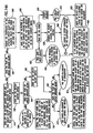
- Figs. 14A and 14B are a simplified flowchart diagram of a method in accordance with an embodiment of the invention for troubleshooting a CUT, such as the CUT 110.
- Figs. 14A and 14B in a simple and systematic method, summarize, combine; and add to the descriptions of procedures that were provided above in more detail
- the user/technician determines whether or not the fuse or circuit breaker is blown (i.e., the fuse or circuit breaker in the CUT). If the fuse or circuit breaker is blown, then it is assumed that the CUT has a short-to-ground fault. On the other hand, if the fuse or circuit breaker is not blown, then it is assumed that the fault would either be due to an open circuit or a high resistance.
- the user/technician turns off the battery master switch (not shown in the drawings) and the CUT on/off switch (see e.g., Fig. 5 for an indication of the CUT on/off switch), and replaces the fuse with another of the correct rating.
- the user/technician turns on the battery master switch (if present).
- the user/technician determines again if the fuse or circuit breaker blows. If the fuse or circuit breaker does blow, at block 540, this indicates that the short-to-ground is in front of (before) the CUT on/off switch.
- the user/technician installs the test leads (e.g., leads 100A and 100B) into the CUT in place of the fuse or circuit breaker (e.g., at the terminal 119A and 119B) and checks to see that the voltmeter (e.g., the voltmeter 108) reads nominal system voltage.
- the user/technician should check all wiring in that part of the circuit that connects the fuse or battery to the CUT on/off switch. The confirmation of the correction of the fault will be if the voltmeter reads a ghost reading.
- the user/technician turns on the CUT on/off switch.
- the user/technician determines, at block 560, whether the fuse or circuit breaker blows. If the fuse or circuit breaker blows, then, at block 570, the short-to-ground is behind (after) the CUT switch. Then, at block 800, the user/technician installs the test leads into the CUT in place of the fuse or circuit breaker (e.g., at the terminals 119A and 119B) and checks to see that the voltmeter reads nominal system voltage.
- the user/technician should check all wiring in that part of the CUT that connects the CUT switch to the component. The confirmation of the correction of the fault will be if the voltmeter reads a ghost reading. If, at block 560, the fuse or circuit breaker instead is not blown, then, at block 580, the short-to-ground is intermittent. At block 810, an intermittent short will require that the user/technician attempt to determine when the short occurs ⁇ either before or after the CUT switch is closed ⁇ and then use the appropriate method described above at blocks 790 or 800.
- the user/technician removes the component in the effected CUT (e.g., light bulb, solenoid, relay coil, horn and the like) and turns the CUT on.
- the user/technician makes sure the voltmeter is on the correct voltage setting (AC or DC) and that the voltmeter is set to auto-range (preferred) or on the correct range.
- the user/technician connects the enhanced test leads into the CUT in place of the component (e.g., at the terminals 117A and 117B), making sure the polarity is correct (e.g., red lead on (+) and black lead on (-)).
- Polarity is important, and if the user/technician sees the negative sign (-) on the voltmeter face, the leads are connected backwards.
- the user/technician determines the reading on the voltmeter.
- the voltmeter reads true zero volts (0.00V)
- the only cause can be from the leads being in contact with each other through the CUT and/or ground. This condition indicates that the CUT is cut (i.e., broken) between the switch and the component, and the wire connected to the component is touching ground.
- the confirmation of the correction of the fault will be the voltmeter reading a nominal voltage.
- the voltmeter reads a ghost reading
- the CUT is open.
- the user/technician then, at block 830, moves the black lead (e.g., 100B) to a machine ground and rereads the voltmeter. If the reading changes to a nominal voltage reading, then the fault is in the ground. If the voltmeter reading remains a ghost reading, then the fault is in the positive portion of the CUT. In either case, the user/technician should check the appropriate wiring for failed or broken connections, or for a wire that is cut or otherwise disconnected.
- the CUT is either corroded or the component has failed.
- the user/technician then, at block 680 (see Fig. 14B through tab A from block 660 in Fig. 14A), activates (i.e., closes or depresses) the (ETL) switch 130 in the leads 100A and 100B to engage the test load 115 in the CUT.
- the user/technician determines the voltmeter reading. If the voltmeter reads nominal system voltage or nearly nominal system voltage, at block 770, then, at block 780, the component has failed. Reaching this point, at block 860, indicates that there are no readable faults or unexpected resistance in the CUT causing an extra voltage drop, and the user/technician should test the component by connecting it to an independent power source to see if it activates or has failed.
- the voltmeter reads, at block 700, significantly below the system voltage (e.g., more than 0.5 volts below system voltage)
- the user/technician then removes the black (-) lead from the component connection, places it upon a convenient machine ground, and activates the switch 130 in the enhanced voltmeter test load circuitry 100.
- the user/technician determines a voltmeter reading. If, at block 730, the reading is again significantly below the system voltage (e.g., more than 0.5 volts below system voltage), then, at block 740, there is added resistance corrosion in the CUT positive side, most likely caused by corrosion.
- the user/technician then should check all wires, connectors and switches, fuse connections and other CUT components in the wire that connects the fuse to the component. Even small amounts of rust or other corrosion can cause the CUT to not operate.
- the voltmeter reads, at block 750, nominal system voltage or nearly nominal system voltage (i.e., changes from low to nominal), then, at block 760, corrosion (high resistance) is present in the CUT negative or ground side.
- corrosion high resistance
- the user/technician should check all wires, connectors, switches, and other circuit components in the wire that connects the component to ground for rust or other corrosion. Even small amounts of rust or other corrosion can cause the CUT to not operate.
- FIGs. 14A and 14B provide the user/technician a workable and systematic procedure to determine the type and location of common circuit faults in electrical systems. Other modifications of these procedures are contemplated, which are included in the spirit and scope of the invention.
Landscapes
- Physics & Mathematics (AREA)
- General Physics & Mathematics (AREA)
- Testing Of Short-Circuits, Discontinuities, Leakage, Or Incorrect Line Connections (AREA)
- Testing Electric Properties And Detecting Electric Faults (AREA)
- Measuring Instrument Details And Bridges, And Automatic Balancing Devices (AREA)
- Organic Low-Molecular-Weight Compounds And Preparation Thereof (AREA)
- Polysaccharides And Polysaccharide Derivatives (AREA)
- Acyclic And Carbocyclic Compounds In Medicinal Compositions (AREA)
- Photoreceptors In Electrophotography (AREA)
- Glass Compositions (AREA)
- Tires In General (AREA)
Applications Claiming Priority (5)
| Application Number | Priority Date | Filing Date | Title |
|---|---|---|---|
| US36006699A | 1999-07-23 | 1999-07-23 | |
| US360066 | 1999-07-23 | ||
| US472425 | 1999-12-27 | ||
| US09/472,425 US6356853B1 (en) | 1999-07-23 | 1999-12-27 | Enhancing voltmeter functionality |
| PCT/US2000/019759 WO2001007871A1 (en) | 1999-07-23 | 2000-07-21 | Enhancing voltmeter functionality |
Publications (3)
| Publication Number | Publication Date |
|---|---|
| EP1203202A1 EP1203202A1 (en) | 2002-05-08 |
| EP1203202A4 EP1203202A4 (en) | 2005-01-12 |
| EP1203202B1 true EP1203202B1 (en) | 2006-03-29 |
Family
ID=27000740
Family Applications (1)
| Application Number | Title | Priority Date | Filing Date |
|---|---|---|---|
| EP00948813A Expired - Lifetime EP1203202B1 (en) | 1999-07-23 | 2000-07-21 | Enhancing voltmeter functionality |
Country Status (8)
| Country | Link |
|---|---|
| US (1) | US6356853B1 (enExample) |
| EP (1) | EP1203202B1 (enExample) |
| JP (1) | JP2003505684A (enExample) |
| AT (1) | ATE322021T1 (enExample) |
| AU (1) | AU6225500A (enExample) |
| CA (1) | CA2380267A1 (enExample) |
| DE (1) | DE60027010T2 (enExample) |
| WO (1) | WO2001007871A1 (enExample) |
Families Citing this family (31)
| Publication number | Priority date | Publication date | Assignee | Title |
|---|---|---|---|---|
| US6646562B1 (en) * | 2002-05-28 | 2003-11-11 | Appa Technology Corp. | Hooking-type fully automatic electric meter |
| BRPI0205470B1 (pt) * | 2002-12-05 | 2017-01-24 | Multibrás S A Eletrodomésticos | sistema de diagnósticos para aparelhos eletrodomésticos |
| US8540493B2 (en) | 2003-12-08 | 2013-09-24 | Sta-Rite Industries, Llc | Pump control system and method |
| US8043070B2 (en) | 2004-08-26 | 2011-10-25 | Pentair Water Pool And Spa, Inc. | Speed control |
| US7686589B2 (en) | 2004-08-26 | 2010-03-30 | Pentair Water Pool And Spa, Inc. | Pumping system with power optimization |
| US7845913B2 (en) | 2004-08-26 | 2010-12-07 | Pentair Water Pool And Spa, Inc. | Flow control |
| US8469675B2 (en) | 2004-08-26 | 2013-06-25 | Pentair Water Pool And Spa, Inc. | Priming protection |
| US8602745B2 (en) | 2004-08-26 | 2013-12-10 | Pentair Water Pool And Spa, Inc. | Anti-entrapment and anti-dead head function |
| US7874808B2 (en) | 2004-08-26 | 2011-01-25 | Pentair Water Pool And Spa, Inc. | Variable speed pumping system and method |
| US8019479B2 (en) | 2004-08-26 | 2011-09-13 | Pentair Water Pool And Spa, Inc. | Control algorithm of variable speed pumping system |
| US8480373B2 (en) | 2004-08-26 | 2013-07-09 | Pentair Water Pool And Spa, Inc. | Filter loading |
| FR2875603A1 (fr) * | 2004-09-20 | 2006-03-24 | Pierre Henri Churlet | Voltmetre a charge adaptee |
| JP4632747B2 (ja) * | 2004-10-29 | 2011-02-16 | 中国電力株式会社 | 電圧計付ヒューズクリップ |
| US7504830B2 (en) * | 2005-06-06 | 2009-03-17 | Associated Equipment Corp. | Dual load tester |
| US7696760B2 (en) * | 2007-11-30 | 2010-04-13 | Caterpillar Inc. | High voltage harness testing system |
| DE102007061729A1 (de) * | 2007-12-20 | 2009-06-25 | Robert Bosch Gmbh | Verfahren zur Erkennung eines elektrischen Fehlers in einem elektrischen Netzwerk eines Kraftfahrzeugs |
| US7777508B2 (en) * | 2008-01-07 | 2010-08-17 | Armstrong Eric A | Electrical test lead with a replaceable inline fuse |
| US7948227B2 (en) * | 2008-09-08 | 2011-05-24 | Beckmann Robert U | Electrical circuit diagnostic tool |
| MX2011003708A (es) | 2008-10-06 | 2011-06-16 | Pentair Water Pool & Spa Inc | Metodo para operar un sistema de seguridad para alivio de vacio. |
| US9556874B2 (en) | 2009-06-09 | 2017-01-31 | Pentair Flow Technologies, Llc | Method of controlling a pump and motor |
| US8564233B2 (en) | 2009-06-09 | 2013-10-22 | Sta-Rite Industries, Llc | Safety system and method for pump and motor |
| MX344350B (es) | 2010-12-08 | 2016-12-13 | Pentair Water Pool & Spa Inc | Válvula de descarga con vacío para sistema de liberación de vacío de seguridad. |
| TW201248383A (en) * | 2011-05-25 | 2012-12-01 | Hon Hai Prec Ind Co Ltd | Power supplying circuit |
| DE102011107206A1 (de) * | 2011-07-13 | 2013-01-17 | Howaldtswerke-Deutsche Werft Gmbh | Verfahren zur Überprüfung einer Messanordnung zur Spannungsbestimmung und Verfahren zum Laden einer ladbaren Spannungsquelle |
| CN102435879B (zh) * | 2011-09-22 | 2013-10-09 | 重庆大学 | 一种合闸前对线路进行检测的方法 |
| CN102818964B (zh) * | 2012-09-12 | 2016-01-13 | 成都光码智能科技有限公司 | 一种基于逆卡诺原理设备工况的监测装置及方法 |
| US9885360B2 (en) | 2012-10-25 | 2018-02-06 | Pentair Flow Technologies, Llc | Battery backup sump pump systems and methods |
| CN103176099B (zh) * | 2013-03-01 | 2015-05-13 | 常熟理工学院 | 低压断路器合闸前主接线短路检测传感装置 |
| US9590537B2 (en) * | 2013-03-15 | 2017-03-07 | Pentair Flow Technologies, Llc | Method of controlling a pump and motor |
| US11249117B2 (en) | 2018-08-02 | 2022-02-15 | Jetperch Llc | Autoranging ammeter with fast dynamic response |
| US12498398B2 (en) * | 2023-02-23 | 2025-12-16 | Snap-On Incorporated | Electrical testing device with probe having an adjustable angle |
Family Cites Families (13)
| Publication number | Priority date | Publication date | Assignee | Title |
|---|---|---|---|---|
| US2432013A (en) * | 1942-04-16 | 1947-12-02 | Du Pont | Measurement of leakage resistance in electrolytic cell systems |
| US2785378A (en) * | 1953-01-30 | 1957-03-12 | Western Electric Co | Electrical measuring system |
| US4001686A (en) * | 1975-05-28 | 1977-01-04 | Storage Technology Corporation | Electronic circuit testing apparatus |
| US4409732A (en) * | 1981-01-05 | 1983-10-18 | John Grant | Circuit isolator |
| US4808915A (en) * | 1981-10-30 | 1989-02-28 | Honeywell Bull, Inc. | Assembly of electronic components testable by a reciprocal quiescent testing technique |
| JPS6144371A (ja) | 1984-08-06 | 1986-03-04 | Mitsubishi Electric Corp | 半導体試験装置 |
| US4709366A (en) * | 1985-07-29 | 1987-11-24 | John Fluke Mfg. Co., Inc. | Computer assisted fault isolation in circuit board testing |
| US4777430A (en) * | 1987-03-16 | 1988-10-11 | American Technical Ceramics Corp. | Circuit for determining the effective series resistance and Q-factor of capacitors |
| US4884034A (en) * | 1989-01-03 | 1989-11-28 | Hermilo Guzman | Ground fault detector and locator |
| JPH03277983A (ja) | 1990-03-28 | 1991-12-09 | Ando Electric Co Ltd | Db型asによるdut負荷切換回路 |
| US5699402A (en) * | 1994-09-26 | 1997-12-16 | Teradyne, Inc. | Method and apparatus for fault segmentation in a telephone network |
| JPH1123635A (ja) * | 1997-07-08 | 1999-01-29 | Ricoh Keiki Kk | 電源用負荷制御方法及びその装置 |
| US5952821A (en) | 1997-08-29 | 1999-09-14 | Credence Systems Corporation | Load circuit for integrated circuit tester |
-
1999
- 1999-12-27 US US09/472,425 patent/US6356853B1/en not_active Expired - Lifetime
-
2000
- 2000-07-21 CA CA002380267A patent/CA2380267A1/en not_active Abandoned
- 2000-07-21 AT AT00948813T patent/ATE322021T1/de active
- 2000-07-21 WO PCT/US2000/019759 patent/WO2001007871A1/en not_active Ceased
- 2000-07-21 EP EP00948813A patent/EP1203202B1/en not_active Expired - Lifetime
- 2000-07-21 DE DE60027010T patent/DE60027010T2/de not_active Expired - Lifetime
- 2000-07-21 JP JP2001512254A patent/JP2003505684A/ja active Pending
- 2000-07-21 AU AU62255/00A patent/AU6225500A/en not_active Abandoned
Also Published As
| Publication number | Publication date |
|---|---|
| AU6225500A (en) | 2001-02-13 |
| ATE322021T1 (de) | 2006-04-15 |
| DE60027010T2 (de) | 2007-06-14 |
| WO2001007871A1 (en) | 2001-02-01 |
| DE60027010D1 (de) | 2006-05-18 |
| US6356853B1 (en) | 2002-03-12 |
| CA2380267A1 (en) | 2001-02-01 |
| EP1203202A4 (en) | 2005-01-12 |
| EP1203202A1 (en) | 2002-05-08 |
| JP2003505684A (ja) | 2003-02-12 |
| WO2001007871A9 (en) | 2002-09-06 |
Similar Documents
| Publication | Publication Date | Title |
|---|---|---|
| EP1203202B1 (en) | Enhancing voltmeter functionality | |
| CN109521359B (zh) | 一种动力电池负极继电器状态检测电路及方法 | |
| US5396172A (en) | Transformer fault analyzer | |
| US5359290A (en) | Method and apparatus using a pair of test circuits having LED indicators for testing engine sensors and ignition modules in vehicles | |
| RU2488131C2 (ru) | Способ и устройство детектирования неисправности в обратной линии нейтрали электрической сети | |
| EP0225904B1 (en) | Improvements in or relating to apparatuses for testing cables | |
| US6559673B2 (en) | Apparatus and method for power continuity testing in a parallel testing system | |
| AU6555699A (en) | Wiring harness diagnostic system | |
| US20040085071A1 (en) | Testing apparatus | |
| US4130794A (en) | Methods and means for identifying and testing circuit connections | |
| EP0418321B1 (en) | A system and a method for detecting and locating liquid leaks | |
| US20230396095A1 (en) | Current Distribution Device Comprising A Load Detection Unit For Measuring A Detection Voltage | |
| US6943555B2 (en) | Redundant safety circuit for squib testing | |
| US5043655A (en) | Current sensing buffer for digital signal line testing | |
| US5631570A (en) | Protective grounding jumper cable tester and testing method | |
| JP2003294803A (ja) | 電気回路の配線の絶縁の健全性を検証するテスター | |
| CZ78294A3 (en) | Process and apparatus for testing electric drive | |
| US7710121B2 (en) | Electrical connector integrity tester | |
| US7071699B2 (en) | Non-load driven fault monitor for electrical circuits | |
| KR100929499B1 (ko) | 자동 복구기능을 구비한 전원차단장치 | |
| US20210311108A1 (en) | Protection adapter for oscilloscope probes | |
| JP4712594B2 (ja) | 接地極付きコンセントの誤接続判別方法および接地極付きコンセントの誤接続判別試験器 | |
| JP2543646B2 (ja) | 接地極付電源コンセントの配線状態検査治具 | |
| KR20000011002A (ko) | 버스 시스템 및 버스 시스템을 통해 서로 연결된 가입자 진단방법 | |
| JPH0954143A (ja) | 半導体試験装置における並列接続する電圧発生器及びコンタクト試験方法 |
Legal Events
| Date | Code | Title | Description |
|---|---|---|---|
| PUAI | Public reference made under article 153(3) epc to a published international application that has entered the european phase |
Free format text: ORIGINAL CODE: 0009012 |
|
| 17P | Request for examination filed |
Effective date: 20020222 |
|
| AK | Designated contracting states |
Kind code of ref document: A1 Designated state(s): AT BE CH CY DE DK ES FI FR GB GR IE IT LI LU MC NL PT SE |
|
| AX | Request for extension of the european patent |
Free format text: AL;LT;LV;MK;RO;SI |
|
| A4 | Supplementary search report drawn up and despatched |
Effective date: 20041125 |
|
| RIC1 | Information provided on ipc code assigned before grant |
Ipc: 7G 01R 1/067 B Ipc: 7G 06F 19/00 B Ipc: 7G 01R 31/28 B Ipc: 7G 01C 25/00 A |
|
| 17Q | First examination report despatched |
Effective date: 20050420 |
|
| GRAP | Despatch of communication of intention to grant a patent |
Free format text: ORIGINAL CODE: EPIDOSNIGR1 |
|
| RIC1 | Information provided on ipc code assigned before grant |
Ipc: 7G 01R 15/12 B Ipc: 7G 01R 1/067 A Ipc: 7G 01R 31/28 B |
|
| GRAS | Grant fee paid |
Free format text: ORIGINAL CODE: EPIDOSNIGR3 |
|
| GRAA | (expected) grant |
Free format text: ORIGINAL CODE: 0009210 |
|
| AK | Designated contracting states |
Kind code of ref document: B1 Designated state(s): AT BE CH CY DE DK ES FI FR GB GR IE IT LI LU MC NL PT SE |
|
| PG25 | Lapsed in a contracting state [announced via postgrant information from national office to epo] |
Ref country code: BE Free format text: LAPSE BECAUSE OF FAILURE TO SUBMIT A TRANSLATION OF THE DESCRIPTION OR TO PAY THE FEE WITHIN THE PRESCRIBED TIME-LIMIT Effective date: 20060329 Ref country code: CH Free format text: LAPSE BECAUSE OF FAILURE TO SUBMIT A TRANSLATION OF THE DESCRIPTION OR TO PAY THE FEE WITHIN THE PRESCRIBED TIME-LIMIT Effective date: 20060329 Ref country code: NL Free format text: LAPSE BECAUSE OF FAILURE TO SUBMIT A TRANSLATION OF THE DESCRIPTION OR TO PAY THE FEE WITHIN THE PRESCRIBED TIME-LIMIT Effective date: 20060329 Ref country code: LI Free format text: LAPSE BECAUSE OF FAILURE TO SUBMIT A TRANSLATION OF THE DESCRIPTION OR TO PAY THE FEE WITHIN THE PRESCRIBED TIME-LIMIT Effective date: 20060329 |
|
| REG | Reference to a national code |
Ref country code: GB Ref legal event code: FG4D |
|
| REG | Reference to a national code |
Ref country code: CH Ref legal event code: EP |
|
| REG | Reference to a national code |
Ref country code: IE Ref legal event code: FG4D |
|
| REF | Corresponds to: |
Ref document number: 60027010 Country of ref document: DE Date of ref document: 20060518 Kind code of ref document: P |
|
| PG25 | Lapsed in a contracting state [announced via postgrant information from national office to epo] |
Ref country code: DK Free format text: LAPSE BECAUSE OF FAILURE TO SUBMIT A TRANSLATION OF THE DESCRIPTION OR TO PAY THE FEE WITHIN THE PRESCRIBED TIME-LIMIT Effective date: 20060629 |
|
| PG25 | Lapsed in a contracting state [announced via postgrant information from national office to epo] |
Ref country code: ES Free format text: LAPSE BECAUSE OF FAILURE TO SUBMIT A TRANSLATION OF THE DESCRIPTION OR TO PAY THE FEE WITHIN THE PRESCRIBED TIME-LIMIT Effective date: 20060710 |
|
| REG | Reference to a national code |
Ref country code: SE Ref legal event code: TRGR |
|
| PG25 | Lapsed in a contracting state [announced via postgrant information from national office to epo] |
Ref country code: MC Free format text: LAPSE BECAUSE OF NON-PAYMENT OF DUE FEES Effective date: 20060731 |
|
| PG25 | Lapsed in a contracting state [announced via postgrant information from national office to epo] |
Ref country code: PT Free format text: LAPSE BECAUSE OF FAILURE TO SUBMIT A TRANSLATION OF THE DESCRIPTION OR TO PAY THE FEE WITHIN THE PRESCRIBED TIME-LIMIT Effective date: 20060829 |
|
| REG | Reference to a national code |
Ref country code: CH Ref legal event code: PL |
|
| NLV1 | Nl: lapsed or annulled due to failure to fulfill the requirements of art. 29p and 29m of the patents act | ||
| ET | Fr: translation filed | ||
| PLBE | No opposition filed within time limit |
Free format text: ORIGINAL CODE: 0009261 |
|
| STAA | Information on the status of an ep patent application or granted ep patent |
Free format text: STATUS: NO OPPOSITION FILED WITHIN TIME LIMIT |
|
| 26N | No opposition filed |
Effective date: 20070102 |
|
| PG25 | Lapsed in a contracting state [announced via postgrant information from national office to epo] |
Ref country code: GR Free format text: LAPSE BECAUSE OF FAILURE TO SUBMIT A TRANSLATION OF THE DESCRIPTION OR TO PAY THE FEE WITHIN THE PRESCRIBED TIME-LIMIT Effective date: 20060630 |
|
| PG25 | Lapsed in a contracting state [announced via postgrant information from national office to epo] |
Ref country code: FI Free format text: LAPSE BECAUSE OF FAILURE TO SUBMIT A TRANSLATION OF THE DESCRIPTION OR TO PAY THE FEE WITHIN THE PRESCRIBED TIME-LIMIT Effective date: 20060329 |
|
| PG25 | Lapsed in a contracting state [announced via postgrant information from national office to epo] |
Ref country code: LU Free format text: LAPSE BECAUSE OF NON-PAYMENT OF DUE FEES Effective date: 20060721 |
|
| PG25 | Lapsed in a contracting state [announced via postgrant information from national office to epo] |
Ref country code: CY Free format text: LAPSE BECAUSE OF FAILURE TO SUBMIT A TRANSLATION OF THE DESCRIPTION OR TO PAY THE FEE WITHIN THE PRESCRIBED TIME-LIMIT Effective date: 20060329 |
|
| PGFP | Annual fee paid to national office [announced via postgrant information from national office to epo] |
Ref country code: AT Payment date: 20110726 Year of fee payment: 12 Ref country code: FR Payment date: 20110816 Year of fee payment: 12 |
|
| PGFP | Annual fee paid to national office [announced via postgrant information from national office to epo] |
Ref country code: IT Payment date: 20110728 Year of fee payment: 12 |
|
| PGFP | Annual fee paid to national office [announced via postgrant information from national office to epo] |
Ref country code: SE Payment date: 20120711 Year of fee payment: 13 Ref country code: IE Payment date: 20120710 Year of fee payment: 13 Ref country code: GB Payment date: 20120718 Year of fee payment: 13 |
|
| PGFP | Annual fee paid to national office [announced via postgrant information from national office to epo] |
Ref country code: DE Payment date: 20120718 Year of fee payment: 13 |
|
| REG | Reference to a national code |
Ref country code: AT Ref legal event code: MM01 Ref document number: 322021 Country of ref document: AT Kind code of ref document: T Effective date: 20120721 |
|
| REG | Reference to a national code |
Ref country code: FR Ref legal event code: ST Effective date: 20130329 |
|
| PG25 | Lapsed in a contracting state [announced via postgrant information from national office to epo] |
Ref country code: FR Free format text: LAPSE BECAUSE OF NON-PAYMENT OF DUE FEES Effective date: 20120731 |
|
| PG25 | Lapsed in a contracting state [announced via postgrant information from national office to epo] |
Ref country code: IT Free format text: LAPSE BECAUSE OF NON-PAYMENT OF DUE FEES Effective date: 20120721 |
|
| PG25 | Lapsed in a contracting state [announced via postgrant information from national office to epo] |
Ref country code: AT Free format text: LAPSE BECAUSE OF NON-PAYMENT OF DUE FEES Effective date: 20120721 |
|
| REG | Reference to a national code |
Ref country code: SE Ref legal event code: EUG |
|
| GBPC | Gb: european patent ceased through non-payment of renewal fee |
Effective date: 20130721 |
|
| REG | Reference to a national code |
Ref country code: IE Ref legal event code: MM4A |
|
| REG | Reference to a national code |
Ref country code: DE Ref legal event code: R119 Ref document number: 60027010 Country of ref document: DE Effective date: 20140201 |
|
| PG25 | Lapsed in a contracting state [announced via postgrant information from national office to epo] |
Ref country code: SE Free format text: LAPSE BECAUSE OF NON-PAYMENT OF DUE FEES Effective date: 20130722 Ref country code: DE Free format text: LAPSE BECAUSE OF NON-PAYMENT OF DUE FEES Effective date: 20140201 Ref country code: GB Free format text: LAPSE BECAUSE OF NON-PAYMENT OF DUE FEES Effective date: 20130721 |
|
| PG25 | Lapsed in a contracting state [announced via postgrant information from national office to epo] |
Ref country code: IE Free format text: LAPSE BECAUSE OF NON-PAYMENT OF DUE FEES Effective date: 20130721 |