EP1202246A2 - Matrixanzeigetafel mit Bildelementen deren Seitenverhältnis auf einem vorausbestimmten Wert eingestellt ist und Anzeigegerät mit dieser Anzeigetafel - Google Patents
Matrixanzeigetafel mit Bildelementen deren Seitenverhältnis auf einem vorausbestimmten Wert eingestellt ist und Anzeigegerät mit dieser Anzeigetafel Download PDFInfo
- Publication number
- EP1202246A2 EP1202246A2 EP01309052A EP01309052A EP1202246A2 EP 1202246 A2 EP1202246 A2 EP 1202246A2 EP 01309052 A EP01309052 A EP 01309052A EP 01309052 A EP01309052 A EP 01309052A EP 1202246 A2 EP1202246 A2 EP 1202246A2
- Authority
- EP
- European Patent Office
- Prior art keywords
- pixels
- display panel
- width
- ratio
- picture data
- Prior art date
- Legal status (The legal status is an assumption and is not a legal conclusion. Google has not performed a legal analysis and makes no representation as to the accuracy of the status listed.)
- Withdrawn
Links
Images




Classifications
-
- H—ELECTRICITY
- H04—ELECTRIC COMMUNICATION TECHNIQUE
- H04N—PICTORIAL COMMUNICATION, e.g. TELEVISION
- H04N5/00—Details of television systems
- H04N5/66—Transforming electric information into light information
-
- G—PHYSICS
- G02—OPTICS
- G02F—OPTICAL DEVICES OR ARRANGEMENTS FOR THE CONTROL OF LIGHT BY MODIFICATION OF THE OPTICAL PROPERTIES OF THE MEDIA OF THE ELEMENTS INVOLVED THEREIN; NON-LINEAR OPTICS; FREQUENCY-CHANGING OF LIGHT; OPTICAL LOGIC ELEMENTS; OPTICAL ANALOGUE/DIGITAL CONVERTERS
- G02F1/00—Devices or arrangements for the control of the intensity, colour, phase, polarisation or direction of light arriving from an independent light source, e.g. switching, gating or modulating; Non-linear optics
- G02F1/01—Devices or arrangements for the control of the intensity, colour, phase, polarisation or direction of light arriving from an independent light source, e.g. switching, gating or modulating; Non-linear optics for the control of the intensity, phase, polarisation or colour
- G02F1/13—Devices or arrangements for the control of the intensity, colour, phase, polarisation or direction of light arriving from an independent light source, e.g. switching, gating or modulating; Non-linear optics for the control of the intensity, phase, polarisation or colour based on liquid crystals, e.g. single liquid crystal display cells
- G02F1/133—Constructional arrangements; Operation of liquid crystal cells; Circuit arrangements
- G02F1/136—Liquid crystal cells structurally associated with a semi-conducting layer or substrate, e.g. cells forming part of an integrated circuit
- G02F1/1362—Active matrix addressed cells
-
- G—PHYSICS
- G09—EDUCATION; CRYPTOGRAPHY; DISPLAY; ADVERTISING; SEALS
- G09G—ARRANGEMENTS OR CIRCUITS FOR CONTROL OF INDICATING DEVICES USING STATIC MEANS TO PRESENT VARIABLE INFORMATION
- G09G2340/00—Aspects of display data processing
- G09G2340/04—Changes in size, position or resolution of an image
-
- G—PHYSICS
- G09—EDUCATION; CRYPTOGRAPHY; DISPLAY; ADVERTISING; SEALS
- G09G—ARRANGEMENTS OR CIRCUITS FOR CONTROL OF INDICATING DEVICES USING STATIC MEANS TO PRESENT VARIABLE INFORMATION
- G09G2340/00—Aspects of display data processing
- G09G2340/04—Changes in size, position or resolution of an image
- G09G2340/0442—Handling or displaying different aspect ratios, or changing the aspect ratio
-
- G—PHYSICS
- G09—EDUCATION; CRYPTOGRAPHY; DISPLAY; ADVERTISING; SEALS
- G09G—ARRANGEMENTS OR CIRCUITS FOR CONTROL OF INDICATING DEVICES USING STATIC MEANS TO PRESENT VARIABLE INFORMATION
- G09G5/00—Control arrangements or circuits for visual indicators common to cathode-ray tube indicators and other visual indicators
- G09G5/003—Details of a display terminal, the details relating to the control arrangement of the display terminal and to the interfaces thereto
- G09G5/005—Adapting incoming signals to the display format of the display terminal
-
- G—PHYSICS
- G09—EDUCATION; CRYPTOGRAPHY; DISPLAY; ADVERTISING; SEALS
- G09G—ARRANGEMENTS OR CIRCUITS FOR CONTROL OF INDICATING DEVICES USING STATIC MEANS TO PRESENT VARIABLE INFORMATION
- G09G5/00—Control arrangements or circuits for visual indicators common to cathode-ray tube indicators and other visual indicators
- G09G5/003—Details of a display terminal, the details relating to the control arrangement of the display terminal and to the interfaces thereto
- G09G5/006—Details of the interface to the display terminal
Definitions
- the present invention relates to a display panel adapted for displaying a television picture for example, and also to a display device equipped with such a display panel.
- LCD liquid crystal display
- CTR cathode ray tubes
- VGA panel VGA control standards
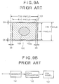
- Fig. 9A shows an effective screen 102a of a VGA panel 102.
- an effective screen is defined as an ,area where a picture can be actually displayed and viewed.
- the effective screen 102a of the VGA panel 102 has a resolution of 640 x 480 pixels.
- Such frame picture data are outputted to the VGA panel at a predetermined timing, and the VGA panel is driven by an unshown driving circuit to display the picture.
- the effective pixels of the frame picture data 101 representing one frame picture are composed of 720 pixels x 483 pixels.
- the video signals are overscanned in such a manner that the image of the edge portion is positioned outside the screen instead of displaying the entire picture within the screen, whereby the image of the edge portion containing some noise components is not displayed.
- the frame picture data 101 is composed of 720 pixels whereas the effective screen 102a is composed of 640 pixels, so that 80 pixels are surplus in the frame picture data 101. For this reason, an overscan area OS of 40 pixels is formed in each of the left and right edge portions equally.
- the frame picture data 101 is composed of 483 pixels whereas the effective screen 102a is composed of 480 pixels, so that 3 pixels are surplus in the frame picture data 101.
- an overscan area OS of 1.5 pixels for example is formed in each of the top and bottom edge portions equally.
- the horizontal overscan quantity is approximately 11% (80 pixels), whereas the vertical overscan quantity is merely 0.6% (3 pixels), whereby a remarkable difference is existent between the horizontal and vertical overscan quantities. If the overscan quantity is insufficient, it is impossible to conceal the noise of the picture edge portion completely. Meanwhile, if the overscan quantity is excessive, the displayed picture area is rendered narrow. As long as no noise appears in the picture data, it is preferred that the widest area be displayed effectively.
- the rate of the overscan quantities needs to be raised as a whole by increasing the vertical overscan quantity to attain a proper value.
- the horizontal overscan quantity which is sufficient from the beginning, is also rendered greater to consequently cause a disadvantage that the horizontal picture range displayed on the effective screen 102a is further narrowed. If a sufficient horizontal picture range is to be ensured in this case, the vertical overscan quantity needs to be maintained small, hence inducing a possibility of failure in completely concealing the noise or distortion that appears in the top and bottom edge portions of the effective screen 102a.
- the frame picture data 101 is processed through reduction or interpolation to be thereby converted into desired frame picture data where the width-to-height ratio of the picture is proper.
- Fig. 9B shows a structural example of a conversion block to execute such conversion of frame picture data.
- input video signals are converted into RGB data by a decoder 121 and then are supplied to a scan converter 122.
- the scan converter 122 executes reduction or interpolation of the input RGB data
- the input RGB data are converted, through reduction of the vertical data thereof, into frame picture data of a proper width-to-height ratio and then are outputted to the VGA panel 102, whereby a desired picture having a proper aspect ratio of 4:3 is displayed on the VGA panel 102.
- Fig. 10A shows an exemplary case where frame picture data are displayed on an effective screen of a VGA panel in such an LCD device.
- masking areas 104a and 104b are formed either electrically or mechanically in the top and bottom portions of an effective screen 102a.
- the horizontal and vertical overscan quantities can be rendered substantially equal to each other by adjusting the masking quantities of such masking areas 104a and 104b.
- the masking areas 104a and 104b each corresponding to 25 pixels are formed in the top and bottom portions of the effective screen 102a respectively.
- Fig. 10B shows a structural example of conversion blocks to convert video signal data for realizing the picture display shown in Fig. 10A.
- the input video signals are converted into RGB data in a decoder 121 and then are inputted to an IP (interlace-progressive) converter 123.
- IP interlace-progressive
- the IP converter 123 converts the input RGB data, which are received field by field, into frame picture data so as to conform the same with the display performed by the LCD panel.
- the frame picture data thus obtained are supplied to a mask generator 124.
- the mask generator 124 executes a predetermined masking process for the top and bottom portions of the frame picture data received from the IP converter 123, and outputs the processed data to the VGA panel 102.
- the production cost is raised due to the necessity of newly providing the mask generator 124 in the conversion block to execute conversion of the video signal data.
- the image of the frame picture data 101 is left contracted in its vertical direction to consequently fail in eliminating the known disadvantage that an elliptical picture 103, which is vertically flat, is displayed in place of an exactly circular picture on the effective screen 102a.
- a display panel where a display screen is formed with matrix-arrayed pixels driven to display a picture.
- the width-to-height ratio of the pixels is set in accordance with a corrective value for achieving a required width-to-height ratio with regard to the picture displayed on the screen, on the basis of the ratio of the number of effective horizontal pixels to the number of effective vertical pixels of the frame picture data obtained by converting the video signals of a predetermined television system into digital video signals in conformity with predetermined standards, and also on the basis of the aspect ratio prescribed by the above television system.
- a display device equipped with a display panel where a display screen is formed with matrix-arrayed pixels driven to display a picture.
- the display panel is so contrived that the width-to-height ratio of the pixels is set in accordance with a corrective value acquired on the basis of the ratio of the number of effective horizontal pixels to the number of effective vertical pixels of the frame picture data obtained by converting the video signals of a predetermined television system into digital video signals in conformity with predetermined standards, and also on the basis of the aspect ratio prescribed by the above television system.
- the display panel is so contrived as to set the width-to-height ratio of the pixels in accordance with a corrective value which is acquired on the basis of the ratio of the number of effective horizontal pixels to the number of effective vertical pixels of the frame picture data obtained by converting the video signals of a predetermined television system into digital video signals in conformity with predetermined standards, and also on the basis of the aspect ratio prescribed by the above television system.
- a desired aspect ratio adapted for each use and the like can be achieved with ease by changeably setting the width-to-height ratio of the pixels with regard to the picture to be displayed on the screen, and a proper picture of the original aspect ratio conforming with the relevant television system can be displayed on the screen. Further, it becomes possible to eliminate the necessity of any signal processing circuit such as a scan converter required heretofore to change the aspect ratio in displaying a television picture in the conventional display device, hence causing no deterioration of the displayed picture quality.
- the horizontal and vertical overscan quantities can be well balanced with facility.
- the display device of any embodiment is not on the premise of displaying a picture of a computer for example, but is one specialized for displaying a television picture.
- the display device of any embodiment is equipped with a liquid crystal display (LCD) panel, whose structure, driving mode and the like may be conventional ones known heretofore.
- LCD liquid crystal display
- the signals are sampled according to sampling clock pulses of 14.31818 MHz, so that one pixel is obtained per sampling clock pulse. Therefore, 910 pixel data are obtained according to 910 sampling clock pulses during 1 line corresponding to one horizontal scanning interval. Further 756 effective pixels are obtained out of such 1-line pixel data.
- the number of scanning lines per frame i.e., the number of lines
- the number of effective lines after such digitization is 480.
- the effective lines described here are different from those in analog form.
- the number of effective lines after digitization is 576.
- sampling frequency and the like are different in the NTSC system and the PAL system as mentioned, so that it has been highly demanded heretofore to realize sampling at a common sampling frequency in both the NTSC and PAL systems.
- CCIR International Radio Consultative Committee
- the sampling frequency is 13.5 MHz in each of the NTSC and PAL systems.
- the number of pixels per line is 858 in the NTSC system or 864 in the PAL system, wherein the number of effective pixels is 720 which is set common to both systems.
- the number of lines per frame is 525 in the NTSC system or 625 in the PAL system, and the number of effective lines after digitization is 480 in the NTSC system or 576 in the PAL system.
- the frame picture data of the NTSC system digitized in conformity with the CCIR601 format is composed of 720 x 483 pixels.
- the frame picture data of the PAL system digitized similarly is composed of 720 x 576 pixels.
- the explanation of this embodiment connotes an exemplary display panel for displaying a picture based on the video signal data of one system (hereinafter referred to as CCIR601-NTSC system) that digitizes the NTSC video signals according to the CCIR601 format, and also another exemplary display panel for displaying a picture based on the video signal data of another system (hereinafter referred to as CCIR601-PAL system) that digitizes the PAL video signals according to the CCIR601 format.
- CCIR601-NTSC system the video signal data of one system
- CCIR601-PAL system another exemplary display panel for displaying a picture based on the video signal data of another system
- FIG. 1A shows an effective screen 1a where a picture is actually displayed in the display panel 1.
- the effective screen 1a is composed of pixels 2 arrayed to form a matrix.
- the display panel 1 in this case has R (red), G (green) and B (blue) light emitting regions in each unit pixel 2 so as to be capable of displaying a color picture.
- the number of pixels in the effective screen 1a is determined by the number of effective pixels of the frame picture data based on the CCIR601 format and also by the set overscan quantity. A detailed description will be given later on the concrete number of pixels in the effective screen 1a.
- the width-to-height ratio of each pixel in the known VGA panel is 1:1.
- the width-to-height ratio of each pixel 2 is 1:1.115 as shown in Fig. 1B. The reason for setting such width-to-height ratio in this embodiment will now be described below.
- the LCD device of this embodiment is so structured as to display video signal data of the CCIR601-NTSC system, as mentioned above.
- the NTSC frame picture data converted according to the CCIR601-NTSC system are composed of 720 x 483 pixels, and therefore the width-to-height ratio (horizontal to vertical) is approximately 4:2.68.
- the CCIR601-NTSC frame picture is displayed on the VGA panel where the width-to-height ratio of each pixel is 1:1 as in the prior art, naturally the displayed picture is contracted in its vertical direction.
- the conventional width-to-height ratio 1:1 of each effective pixel is so changed that the aspect ratio of the picture displayed on the effective screen 1a is corrected to 4:3.
- the width-to-height ratio of the frame picture data is expressed as a:b, where a denotes the number of effective pixels in the horizontal direction (width) of the frame picture data, and b denotes the number of effective lines in the vertical direction (height) of the frame picture data.
- the aspect ratio of the original picture to be displayed is expressed as c (width):d (height).
- the desired aspect can be obtained by changing the width-to-height ratio a:b of the picture to c:d.
- CRCT (a x d) / (b x c)
- the total number of effective pixels in the CCIR601-NTSC frame picture data is 720 x 483, and the aspect ratio of the NTSC picture is 4:3, so that the corrective value is obtained from Eq. 2 as
- the height may be set to 1.115 in comparison with the width of 1 as a reference. That is, the corrective value regarding the width-to-height ratio of each pixel may be set to 1 (width):1.115 (height), and this ratio is coincident with the width-to-height ratio of each pixel 2 in this embodiment shown in Fig. 1B.
- the image picture obtained by displaying the frame picture data of a width-to-height ratio 4:2.68 is enlarged 1.115 times only in its vertical direction to consequently change the aspect ratio of the image picture displayed on the effective screen 1a to 4:3 as a whole. As a result, a proper picture can be displayed without any contraction on the display panel 1.
- the video signal data obtained by conversion from the television signals also contain the noise components in the data portions corresponding to the edges of the frame picture.
- the vertical and horizontal overscan quantities be well balanced so as to ensure the possibly widest display area without displaying any noise or the like.
- the experimental result achieved signifies that, on the basis of the relationship between the actual frame picture data 3 and the effective screen 1a for example, satisfactory display of a picture without any practical problem can be realized by obtaining an overscan quantity of approximately 5% in total in the vertical and horizontal directions with respect to the frame picture data 3.
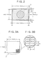
- An overscan area OS of approximately 2.5% is allocated to each of the left and right edges equally in the vertical direction, as shown in Fig. 2.
- an overscan area OS of approximately 2.5% is allocated to each of the top and bottom edges equally in the horizontal direction.
- the number of pixels occupying the effective screen 1a of the display panel 1 is finally determined by the overscan quantity thus set.
- the number of horizontal pixels and that of vertical pixels in the effective screen 1a may be 95% of the number of horizontal pixels and that of vertical pixels of the frame picture data 3, respectively. Therefore, as shown in Fig. 2, the number of horizontal pixels in the effective screen 1a may be 684 pixels equivalent to 95% of 720 effective pixels of the CCIR601-NTSC frame picture data 3. Similarly, the number of vertical pixels in the effective screen 1a may be 459 pixels equivalent to 95% of 483 effective pixels of the frame picture data 3.
- Fig. 8 represents an exemplary case of 480 vertical pixels in the CCIR601-NTSC system, there may be another case of 483 vertical pixels as shown in Fig. 2. For example, in the case of conforming with HDTV also, there may be 483 pixels.
- the display panel 1 of this embodiment is so contrived as to change the width-to-height ratio of each unit pixel 2 by the corrective value calculated as mentioned on the basis of the width-to-height ratio of the picture data and also the aspect ratio 4:3 prescribed in the NTSC system. Consequently, despite input and display of any picture where the width-to-height ratio of the effective pixels thereof is not 4:3 such as frame picture data of the CCIR601-NTSC system, it is still possible to realize display of a proper picture without any image contraction on the effective screen 1a.
- This second embodiment represents a display panel corresponding to PAL frame picture data digitized in conformity with the CCIR601 format.
- an effective screen 11a of a display panel 11 shown in Fig. 3A there are arrayed stationary pixels composed of X pixels x Y pixels.
- the respective numbers of such pixels in this effective screen 11a are determined by overscan quantities of the frame picture data, as will be described later.
- the concrete numbers of unit pixels in the effective screen 11a will also be described later.
- the unit pixels 12 shown in an enlarged view of Fig. 3B are arrayed to form a matrix in the same manner as the aforementioned unit pixels 2 shown in Fig. 1B.
- the frame picture data 13 of each CCIR601-PAL frame are composed of 720 x 576 pixels.
- picture signals originally having an aspect ratio of 4:3 are converted into frame picture data of 4:3.2 (720:576), whereby the picture of the frame data 13 is expanded in its vertical direction.
- the corrective value CRCT required in this case is calculated as follows.
- the number of effective pixels in the CCIR601-PAL frame picture data is 720 x 576, and the aspect ratio of the PAL picture is 4:3. Accordingly, the corrective value is obtained from Eq. 2 as in the first embodiment.
- the height may be set to 0.940 in comparison with the width of 1 as a reference, as shown in Fig. 3B.
- the aspect ratio of the picture displayed on the effective screen 11a can be corrected to 4:3 by setting the width-to-height ratio of each unit pixel 12 in the display panel 11 to 1 (width) : 0.940 (height).
- the overscan quantity is set to 5% of the frame picture data as shown in Fig. 4, the number of horizontal pixels on the effective screen 11a is 684 pixels equivalent to 95% of the 720 effective pixels of the frame picture data 13, as shown in Fig. 4.
- the number of vertical pixels on the effective screen 11a is 548 pixels equivalent to 95% of the 576 effective lines.
- the display panel 1 (11) of each embodiment described above is concerned with an exemplary case where the overscan quantity in displaying the picture on the effective screen 1a (11a) is set approximately to 5% of the frame picture data 3 (13).
- the actual overscan quantity may be changed to any other adequate value in conformity with the specification and the like of the display panel 1 (11).
- the overscan quantity can be set to a smaller value for widening the picture range to be displayed on the effective screen 1a, or the overscan quantity can be set to a greater value when enlarging the picture to be displayed on the effective screen 1a.
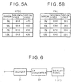
- Figs. 5A and 5B show the relationship between the overscan quantities and the numbers of pixels of the effective screen in the display panel of each embodiment.
- Fig. 5A there is shown an example of the relationship between the overscan quantities and the numbers of pixels of the effective screen 1a in the display panel 1 corresponding to the NTSC system shown in Fig. 2.
- the overscan quantity is set to 5% of the frame picture data with 684 horizontal pixels equivalent approximately to 95% of the 720 effective pixels of the frame picture data 3, and with 460 vertical pixels equivalent approximately to 95% of the 480 effective lines of the frame picture data 3.
- the overscan quantity is set to 3% of the frame picture data with 698 horizontal pixels and 470 vertical pixels.
- the overscan quantity is set to 7% with 670 horizontal pixels and 450 vertical pixels.
- the overscan quantity is set to 10% with 648 horizontal pixels and 436 vertical pixels.
- Fig. 5B there is shown an example of the relationship between the overscan quantities and the numbers of pixels of the effective screen 11a in the display panel 11 corresponding to the PAL system shown in Fig. 4.
- the overscan quantity is set to 3% of the frame picture data with 698 horizontal pixels and 560 vertical pixels.
- the overscan quantity is set to 7% of the frame picture data with 670 horizontal pixels and 536 vertical pixels.
- the overscan quantity is set to 10% with 648 horizontal pixels and 520 vertical pixels.
- the overscan quantity is changed in such display device, the number of pixels of the effective screen is also changed in proportion thereto. Accordingly, when the overscan quantity is increased for example, the number of pixels of the effective screen is diminished to consequently reduce the size of the effective screen. In this case, therefore, the size of the effective screen can be altered to the former size by enlarging the shape of the entire unit pixels formed on the effective screen.
- Fig. 6 schematically shows a structural example of the data conversion block furnished in the display device of this embodiment.
- input NTSC or PAL video signals are converted by a decoder 21 into RGB data and then are supplied to an IP converter 22.
- the IP converter 22 converts the RGB data, which are inputted field by field, into picture data of each frame in conformity with the CCIR601 format mentioned above, and then outputs the frame picture data to the display panel 1 (11) at a predetermined timing. Subsequently the display panel 1 (11) is driven by an unshown driving circuit so that the picture is displayed on the effective screen 1a (11b) as described.
- the image quality of the displayed picture is not deteriorated either.
- the display panel of this embodiment can be manufactured in accordance with the known VGA panel production process merely by altering the shape of a mask used to form pixels of a predetermined width-to-height ratio. Therefore, another advantage is attainable in the point that the production cost of the display panel of this embodiment is suppressed to be substantially equal to that of the conventional VGA panel.
- the aspect ratio of the displayed picture is corrected by changing the width-to-ratio of each pixel itself while fixing the interval between mutually adjacent pixels formed physically on the display panel.
- the aspect ratio of the displayed picture can also be corrected by a modified structure which will be described below.
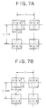
- Figs. 7A and 7B show an enlarged view of pixels arrayed to form a matrix on the display panel.
- the width-to-height ratio of each pixel 2 is set to 1:1 as in the conventional VGA panel shown in the diagram, wherein the distance between horizontally adjacent pixels and the distance between vertically adjacent pixels are set to a ratio of 1:1.115.
- the width-to-height ratio of each pixel 2 is set also to 1:1 as shown in Fig. 7B, and the distance between horizontally adjacent pixels and the distance between vertically adjacent pixels are set to a ratio of 1:0.940.
- a block area consisting of an aggregation of four pixels, in which two pixels are existent in each of horizontal and vertical directions, is regarded as one pixel, and the ratio of the horizontal distance to the vertical distance between such block areas is changed to obtain a width-to-height ratio of 1:1.115 with regard to the pixels of the CCIR601-NTSC system.
- each of the embodiments mentioned above is concerned with an LCD device, it is merely an example, and the display panel and the display device of the present invention are applicable to, e.g., an LED display device using light emitting diodes as pixels or a display device using a fluorescent display tube or the like on condition that individual pixels are arrayed to form a matrix.
- the above embodiments have been explained with reference to exemplary display panels that conform with frame picture data obtained by digitizing video signals of the NTSC system and the PAL system respectively into the CCIR601 format.
- the present invention is not limited to such examples alone, and it may be applied to a display panel corresponding to frame picture data obtained by converting, e.g., picture data of the SECAM system into the CCIR601 format.
- the present invention is applicable also to any video signal data obtained by digitizing the video signals into some other conversion format than the CCIR601 format.
Landscapes
- Physics & Mathematics (AREA)
- Nonlinear Science (AREA)
- Engineering & Computer Science (AREA)
- Mathematical Physics (AREA)
- Chemical & Material Sciences (AREA)
- Crystallography & Structural Chemistry (AREA)
- Microelectronics & Electronic Packaging (AREA)
- General Physics & Mathematics (AREA)
- Optics & Photonics (AREA)
- Multimedia (AREA)
- Signal Processing (AREA)
- Control Of Indicators Other Than Cathode Ray Tubes (AREA)
- Transforming Electric Information Into Light Information (AREA)
- Liquid Crystal Display Device Control (AREA)
- Devices For Indicating Variable Information By Combining Individual Elements (AREA)
Applications Claiming Priority (4)
| Application Number | Priority Date | Filing Date | Title |
|---|---|---|---|
| JP2000332112 | 2000-10-25 | ||
| JP2000332112 | 2000-10-25 | ||
| JP2001174022A JP4144193B2 (ja) | 2000-10-25 | 2001-06-08 | 表示パネル、及びディスプレイ装置 |
| JP2001174022 | 2001-06-08 |
Publications (2)
| Publication Number | Publication Date |
|---|---|
| EP1202246A2 true EP1202246A2 (de) | 2002-05-02 |
| EP1202246A3 EP1202246A3 (de) | 2007-05-09 |
Family
ID=26603110
Family Applications (1)
| Application Number | Title | Priority Date | Filing Date |
|---|---|---|---|
| EP01309052A Withdrawn EP1202246A3 (de) | 2000-10-25 | 2001-10-25 | Matrixanzeigetafel mit Bildelementen deren Seitenverhältnis auf einem vorausbestimmten Wert eingestellt ist und Anzeigegerät mit dieser Anzeigetafel |
Country Status (6)
| Country | Link |
|---|---|
| US (1) | US6970205B2 (de) |
| EP (1) | EP1202246A3 (de) |
| JP (1) | JP4144193B2 (de) |
| KR (1) | KR100777666B1 (de) |
| CN (1) | CN1175364C (de) |
| TW (1) | TW525142B (de) |
Cited By (1)
| Publication number | Priority date | Publication date | Assignee | Title |
|---|---|---|---|---|
| EP1853060A1 (de) * | 2006-05-04 | 2007-11-07 | Syntax Brillian Corp. | Verfahren zum Skalen kontrollieren und Bild abschneiden für eine Fernsehanzeigevorrichtung |
Families Citing this family (6)
| Publication number | Priority date | Publication date | Assignee | Title |
|---|---|---|---|---|
| US7098936B2 (en) * | 2003-03-11 | 2006-08-29 | Hewlett-Packard Development Company, L.P. | Image display system and method including optical scaling |
| CN101627334B (zh) * | 2007-04-16 | 2011-07-20 | 夏普株式会社 | 显示装置、显示装置的驱动装置、及电子设备 |
| KR101500957B1 (ko) * | 2008-10-30 | 2015-03-12 | 삼성전자주식회사 | 영상처리 장치 및 방법 |
| US20140010277A1 (en) * | 2012-07-09 | 2014-01-09 | Qualcomm, Incorporated | Supplemental enhancement information (sei) messages having a fixed-length coded video parameter set (vps) id |
| JP6171425B2 (ja) * | 2013-03-12 | 2017-08-02 | セイコーエプソン株式会社 | 虚像表示装置 |
| CN108012180B (zh) * | 2017-12-06 | 2020-12-08 | 深圳Tcl新技术有限公司 | 节目播放方法、电视及存储介质 |
Family Cites Families (25)
| Publication number | Priority date | Publication date | Assignee | Title |
|---|---|---|---|---|
| US4920409A (en) * | 1987-06-23 | 1990-04-24 | Casio Computer Co., Ltd. | Matrix type color liquid crystal display device |
| JP2909079B2 (ja) * | 1988-09-13 | 1999-06-23 | 株式会社東芝 | 表示制御方式 |
| DE69210303T2 (de) * | 1991-05-23 | 1996-11-14 | Hitachi Ltd | Breitbildschirmfernsehempfänger mit Bildseitenverhältnisumwandlungsfunktion und Verfahren zur Darstellung eines vergrösserten Abschnittes |
| KR960015397B1 (ko) * | 1993-03-17 | 1996-11-11 | 엘지전자 주식회사 | 사이드컷 모드 및 상하절단 모드를 적용한 고화질 티브이신호 변환회로 |
| JP3231142B2 (ja) * | 1993-06-18 | 2001-11-19 | 株式会社日立製作所 | 映像圧縮拡大回路及び装置 |
| JP3329009B2 (ja) * | 1993-06-30 | 2002-09-30 | ソニー株式会社 | アクティブマトリクス表示装置 |
| JP3128034B2 (ja) * | 1993-11-18 | 2001-01-29 | 日本ビクター株式会社 | 画像合成装置 |
| JPH0851600A (ja) * | 1994-08-04 | 1996-02-20 | Sanyo Electric Co Ltd | 映像信号変換装置 |
| JP3362538B2 (ja) * | 1994-12-06 | 2003-01-07 | ソニー株式会社 | ビデオ信号処理装置及びビデオ信号再生装置 |
| DE69522013T2 (de) * | 1995-04-07 | 2002-03-28 | Ifire Technology Inc., Fort Saskatchewan | Ausleseschaltung für eine bildmatrix mit aktiver matrix |
| JPH09294250A (ja) * | 1996-04-26 | 1997-11-11 | Sony Corp | 走査線変換装置 |
| KR100194922B1 (ko) * | 1996-04-29 | 1999-06-15 | 윤종용 | 화면비 변환장치 |
| JPH09307861A (ja) * | 1996-05-17 | 1997-11-28 | Sony Corp | 信号処理方法及び信号処理装置 |
| US6380979B1 (en) * | 1996-07-02 | 2002-04-30 | Matsushita Electric Industrial Co., Ltd. | Scanning line converting circuit and interpolation coefficient generating circuit |
| JP3742167B2 (ja) * | 1996-12-18 | 2006-02-01 | 株式会社東芝 | 画像表示制御装置 |
| KR19980052322A (ko) * | 1996-12-24 | 1998-09-25 | 구자홍 | 티브이의 자동 화면비 검출방법 및 보정장치 |
| JPH11109391A (ja) * | 1997-10-01 | 1999-04-23 | Sanyo Electric Co Ltd | 液晶表示装置 |
| JP3398025B2 (ja) * | 1997-10-01 | 2003-04-21 | 三洋電機株式会社 | 液晶表示装置 |
| JP3349935B2 (ja) * | 1997-12-05 | 2002-11-25 | アルプス電気株式会社 | アクティブマトリクス型液晶表示装置 |
| JP3798150B2 (ja) * | 1998-07-07 | 2006-07-19 | 株式会社リコー | 画像処理方法及び画像処理装置 |
| JP2000184185A (ja) * | 1998-12-15 | 2000-06-30 | Canon Inc | 解像度変換装置、方法及びコンピュータ読み取り可能な記憶媒体 |
| US6115072A (en) * | 1999-01-27 | 2000-09-05 | Motorola, Inc. | 16:9 aspect ratio conversion by letterbox method for an MPEG image |
| JP2000338925A (ja) * | 1999-05-28 | 2000-12-08 | Alps Electric Co Ltd | 映像表示装置 |
| KR100312755B1 (ko) * | 1999-06-03 | 2001-11-03 | 윤종용 | 멀티싱크를 위한 액정 표시 장치 및 디스플레이 장치와 각각의 구동 장치 |
| US6690425B1 (en) * | 2000-06-22 | 2004-02-10 | Thomson Licensing S.A. | Aspect ratio control arrangement in a video display |
-
2001
- 2001-06-08 JP JP2001174022A patent/JP4144193B2/ja not_active Expired - Fee Related
- 2001-10-08 TW TW090124849A patent/TW525142B/zh not_active IP Right Cessation
- 2001-10-12 KR KR1020010062814A patent/KR100777666B1/ko not_active Expired - Fee Related
- 2001-10-19 US US10/002,755 patent/US6970205B2/en not_active Expired - Fee Related
- 2001-10-25 EP EP01309052A patent/EP1202246A3/de not_active Withdrawn
- 2001-10-25 CN CNB011375027A patent/CN1175364C/zh not_active Expired - Fee Related
Non-Patent Citations (1)
| Title |
|---|
| None |
Cited By (1)
| Publication number | Priority date | Publication date | Assignee | Title |
|---|---|---|---|---|
| EP1853060A1 (de) * | 2006-05-04 | 2007-11-07 | Syntax Brillian Corp. | Verfahren zum Skalen kontrollieren und Bild abschneiden für eine Fernsehanzeigevorrichtung |
Also Published As
| Publication number | Publication date |
|---|---|
| US6970205B2 (en) | 2005-11-29 |
| KR20020032307A (ko) | 2002-05-03 |
| CN1350275A (zh) | 2002-05-22 |
| TW525142B (en) | 2003-03-21 |
| JP2002202751A (ja) | 2002-07-19 |
| CN1175364C (zh) | 2004-11-10 |
| JP4144193B2 (ja) | 2008-09-03 |
| EP1202246A3 (de) | 2007-05-09 |
| KR100777666B1 (ko) | 2007-11-21 |
| US20020047855A1 (en) | 2002-04-25 |
Similar Documents
| Publication | Publication Date | Title |
|---|---|---|
| CA2429934C (en) | Method and apparatus for interface-progressive video conversion | |
| US5796442A (en) | Multi-format television reciever | |
| EP0566229A2 (de) | Verfahren und Einrichtung zum Aufheben des Zeilensprungverfahren von Videoeingangssignalen | |
| TW511073B (en) | A method and apparatus in a computer system to generate a downscaled video image for display on a television system | |
| US6970205B2 (en) | Display panel with aspect ratio of matrix-arrayed pixels set to predetermined value, and display device using such display panel | |
| JPH08251504A (ja) | ビデオディスプレイシステム | |
| EP1600005B1 (de) | Verarbeitung von signalen für eine farbsequentielle anzeige | |
| US7397517B2 (en) | Display system and signal processing using diamond-shaped DMDs | |
| US7701519B2 (en) | Display system and signal processing using diamond-shaped DMDs | |
| US7202900B2 (en) | Method of producing frame pair signals from an image sensor and method for displaying same | |
| JPH01194575A (ja) | ビデオディスプレイ装置 | |
| JPH01231474A (ja) | 画像表示管焼付防止方法 | |
| JP2621190B2 (ja) | X−yマトリクス表示装置 | |
| KR100196922B1 (ko) | 4판식 이미지 센서를 이용한 고해상도 영상 신호처리 장치 및 방법 | |
| KR100207984B1 (ko) | 3판식 이미지 센서를 이용한 고해상도 촬상 장치 | |
| JPH03175782A (ja) | テレビジヨン受像機 | |
| KR100231007B1 (ko) | 4판식 이미지 센서를 이용한 고해상도 촬상 장치 및 화소 배치 방법 | |
| KR100225034B1 (ko) | 이중 포트 수평 전달 레지스터 ccd를 이용한 4판식 촬상 장치 | |
| JPH0486083A (ja) | 表示装置 | |
| JPH04352581A (ja) | 液晶表示装置の駆動回路 | |
| JPH05328315A (ja) | 映像信号の方式変換装置 | |
| JP2003198991A (ja) | テレビジョン受信機 | |
| JPH0222996A (ja) | 立体画像表示装置 | |
| JPH02222285A (ja) | ハイビジョン―ntsc変換装置 | |
| JPH03258086A (ja) | 高品位テレビジョン受像機 |
Legal Events
| Date | Code | Title | Description |
|---|---|---|---|
| PUAI | Public reference made under article 153(3) epc to a published international application that has entered the european phase |
Free format text: ORIGINAL CODE: 0009012 |
|
| AK | Designated contracting states |
Kind code of ref document: A2 Designated state(s): AT BE CH CY DE DK ES FI FR GB GR IE IT LI LU MC NL PT SE TR |
|
| AX | Request for extension of the european patent |
Free format text: AL;LT;LV;MK;RO;SI |
|
| PUAL | Search report despatched |
Free format text: ORIGINAL CODE: 0009013 |
|
| AK | Designated contracting states |
Kind code of ref document: A3 Designated state(s): AT BE CH CY DE DK ES FI FR GB GR IE IT LI LU MC NL PT SE TR |
|
| AX | Request for extension of the european patent |
Extension state: AL LT LV MK RO SI |
|
| RIC1 | Information provided on ipc code assigned before grant |
Ipc: G02F 1/1362 20060101ALI20070330BHEP Ipc: G09G 3/20 20060101ALI20070330BHEP Ipc: G09G 3/36 20060101AFI20020204BHEP |
|
| 17P | Request for examination filed |
Effective date: 20070731 |
|
| AKX | Designation fees paid |
Designated state(s): DE FR GB |
|
| 17Q | First examination report despatched |
Effective date: 20080902 |
|
| STAA | Information on the status of an ep patent application or granted ep patent |
Free format text: STATUS: THE APPLICATION IS DEEMED TO BE WITHDRAWN |
|
| 18D | Application deemed to be withdrawn |
Effective date: 20160503 |