EP1198323B1 - Reibgeschweisstes welle-scheibe-verbundwerkstuck und verfahren zu seiner herstellung - Google Patents
Reibgeschweisstes welle-scheibe-verbundwerkstuck und verfahren zu seiner herstellung Download PDFInfo
- Publication number
- EP1198323B1 EP1198323B1 EP00942092A EP00942092A EP1198323B1 EP 1198323 B1 EP1198323 B1 EP 1198323B1 EP 00942092 A EP00942092 A EP 00942092A EP 00942092 A EP00942092 A EP 00942092A EP 1198323 B1 EP1198323 B1 EP 1198323B1
- Authority
- EP
- European Patent Office
- Prior art keywords
- shaft
- disk
- webs
- steps
- composite component
- Prior art date
- Legal status (The legal status is an assumption and is not a legal conclusion. Google has not performed a legal analysis and makes no representation as to the accuracy of the status listed.)
- Expired - Lifetime
Links
- 238000000034 method Methods 0.000 title claims description 11
- 238000004519 manufacturing process Methods 0.000 title claims description 5
- 238000003466 welding Methods 0.000 claims abstract description 42
- 239000002131 composite material Substances 0.000 claims description 40
- 229910052751 metal Inorganic materials 0.000 claims description 18
- 239000002184 metal Substances 0.000 claims description 18
- 239000000463 material Substances 0.000 claims description 10
- 229910000831 Steel Inorganic materials 0.000 claims description 2
- 239000010959 steel Substances 0.000 claims description 2
- 239000012530 fluid Substances 0.000 claims 1
- 239000011343 solid material Substances 0.000 abstract description 2
- 239000000126 substance Substances 0.000 abstract 1
- 238000005304 joining Methods 0.000 description 8
- 239000003921 oil Substances 0.000 description 6
- 230000005540 biological transmission Effects 0.000 description 4
- 238000001816 cooling Methods 0.000 description 3
- 239000003562 lightweight material Substances 0.000 description 3
- 239000010687 lubricating oil Substances 0.000 description 3
- 239000007787 solid Substances 0.000 description 3
- 229910000975 Carbon steel Inorganic materials 0.000 description 2
- 229910052782 aluminium Inorganic materials 0.000 description 2
- XAGFODPZIPBFFR-UHFFFAOYSA-N aluminium Chemical compound [Al] XAGFODPZIPBFFR-UHFFFAOYSA-N 0.000 description 2
- 239000010962 carbon steel Substances 0.000 description 2
- 238000010438 heat treatment Methods 0.000 description 2
- 229910000760 Hardened steel Inorganic materials 0.000 description 1
- 239000011324 bead Substances 0.000 description 1
- 238000009826 distribution Methods 0.000 description 1
- 239000011261 inert gas Substances 0.000 description 1
- 239000007788 liquid Substances 0.000 description 1
- 230000001050 lubricating effect Effects 0.000 description 1
- 238000003754 machining Methods 0.000 description 1
- 238000011089 mechanical engineering Methods 0.000 description 1
- 238000003825 pressing Methods 0.000 description 1
- 238000005096 rolling process Methods 0.000 description 1
Images


Classifications
-
- F—MECHANICAL ENGINEERING; LIGHTING; HEATING; WEAPONS; BLASTING
- F16—ENGINEERING ELEMENTS AND UNITS; GENERAL MEASURES FOR PRODUCING AND MAINTAINING EFFECTIVE FUNCTIONING OF MACHINES OR INSTALLATIONS; THERMAL INSULATION IN GENERAL
- F16D—COUPLINGS FOR TRANSMITTING ROTATION; CLUTCHES; BRAKES
- F16D1/00—Couplings for rigidly connecting two coaxial shafts or other movable machine elements
- F16D1/06—Couplings for rigidly connecting two coaxial shafts or other movable machine elements for attachment of a member on a shaft or on a shaft-end
- F16D1/064—Couplings for rigidly connecting two coaxial shafts or other movable machine elements for attachment of a member on a shaft or on a shaft-end non-disconnectable
- F16D1/068—Couplings for rigidly connecting two coaxial shafts or other movable machine elements for attachment of a member on a shaft or on a shaft-end non-disconnectable involving gluing, welding or the like
-
- B—PERFORMING OPERATIONS; TRANSPORTING
- B23—MACHINE TOOLS; METAL-WORKING NOT OTHERWISE PROVIDED FOR
- B23K—SOLDERING OR UNSOLDERING; WELDING; CLADDING OR PLATING BY SOLDERING OR WELDING; CUTTING BY APPLYING HEAT LOCALLY, e.g. FLAME CUTTING; WORKING BY LASER BEAM
- B23K20/00—Non-electric welding by applying impact or other pressure, with or without the application of heat, e.g. cladding or plating
- B23K20/12—Non-electric welding by applying impact or other pressure, with or without the application of heat, e.g. cladding or plating the heat being generated by friction; Friction welding
- B23K20/129—Non-electric welding by applying impact or other pressure, with or without the application of heat, e.g. cladding or plating the heat being generated by friction; Friction welding specially adapted for particular articles or workpieces
-
- B—PERFORMING OPERATIONS; TRANSPORTING
- B29—WORKING OF PLASTICS; WORKING OF SUBSTANCES IN A PLASTIC STATE IN GENERAL
- B29C—SHAPING OR JOINING OF PLASTICS; SHAPING OF MATERIAL IN A PLASTIC STATE, NOT OTHERWISE PROVIDED FOR; AFTER-TREATMENT OF THE SHAPED PRODUCTS, e.g. REPAIRING
- B29C65/00—Joining or sealing of preformed parts, e.g. welding of plastics materials; Apparatus therefor
- B29C65/02—Joining or sealing of preformed parts, e.g. welding of plastics materials; Apparatus therefor by heating, with or without pressure
- B29C65/06—Joining or sealing of preformed parts, e.g. welding of plastics materials; Apparatus therefor by heating, with or without pressure using friction, e.g. spin welding
- B29C65/0672—Spin welding
-
- B—PERFORMING OPERATIONS; TRANSPORTING
- B29—WORKING OF PLASTICS; WORKING OF SUBSTANCES IN A PLASTIC STATE IN GENERAL
- B29C—SHAPING OR JOINING OF PLASTICS; SHAPING OF MATERIAL IN A PLASTIC STATE, NOT OTHERWISE PROVIDED FOR; AFTER-TREATMENT OF THE SHAPED PRODUCTS, e.g. REPAIRING
- B29C66/00—General aspects of processes or apparatus for joining preformed parts
- B29C66/01—General aspects dealing with the joint area or with the area to be joined
- B29C66/342—Preventing air-inclusions
-
- B—PERFORMING OPERATIONS; TRANSPORTING
- B29—WORKING OF PLASTICS; WORKING OF SUBSTANCES IN A PLASTIC STATE IN GENERAL
- B29C—SHAPING OR JOINING OF PLASTICS; SHAPING OF MATERIAL IN A PLASTIC STATE, NOT OTHERWISE PROVIDED FOR; AFTER-TREATMENT OF THE SHAPED PRODUCTS, e.g. REPAIRING
- B29C66/00—General aspects of processes or apparatus for joining preformed parts
- B29C66/50—General aspects of joining tubular articles; General aspects of joining long products, i.e. bars or profiled elements; General aspects of joining single elements to tubular articles, hollow articles or bars; General aspects of joining several hollow-preforms to form hollow or tubular articles
- B29C66/51—Joining tubular articles, profiled elements or bars; Joining single elements to tubular articles, hollow articles or bars; Joining several hollow-preforms to form hollow or tubular articles
- B29C66/53—Joining single elements to tubular articles, hollow articles or bars
- B29C66/534—Joining single elements to open ends of tubular or hollow articles or to the ends of bars
- B29C66/5344—Joining single elements to open ends of tubular or hollow articles or to the ends of bars said single elements being substantially annular, i.e. of finite length, e.g. joining flanges to tube ends
-
- Y—GENERAL TAGGING OF NEW TECHNOLOGICAL DEVELOPMENTS; GENERAL TAGGING OF CROSS-SECTIONAL TECHNOLOGIES SPANNING OVER SEVERAL SECTIONS OF THE IPC; TECHNICAL SUBJECTS COVERED BY FORMER USPC CROSS-REFERENCE ART COLLECTIONS [XRACs] AND DIGESTS
- Y10—TECHNICAL SUBJECTS COVERED BY FORMER USPC
- Y10T—TECHNICAL SUBJECTS COVERED BY FORMER US CLASSIFICATION
- Y10T428/00—Stock material or miscellaneous articles
- Y10T428/12—All metal or with adjacent metals
- Y10T428/12493—Composite; i.e., plural, adjacent, spatially distinct metal components [e.g., layers, joint, etc.]
Definitions
- the invention relates to a shaft-disc composite workpiece, which by friction welding as well as a method for its production.
- a method is known by means of which a shaft and a Disc can be connected in a connection region by friction welding.
- the shaft is in the connection area with a conical or stepped outer surface provided while the disc with a the connection area on the shaft corresponding conical or stepped through hole is provided.
- This design the connection area causes a centering of the shaft relative to the disc during the friction welding process.
- the invention is therefore based on the object, one over the prior art to propose weight-reduced shaft-disc composite piece, the low Mass moment of inertia relative to the axis of rotation. Furthermore, the invention is the task is based on a method for producing such a composite workpiece propose.
- the shaft is in a connection area in which the disc with the shaft is to be welded, provided with a plurality of rotationally symmetric steps whose Diameter increases in one direction of the axis increasingly.
- the disk provided in the region of the axis of rotation with a through hole; the Through hole is designed so that it has several rotationally symmetrical webs, which protrude from the disk to the axis of rotation.
- the inner diameter of the webs is chosen so that each web forms a through hole, the inner diameter of a Weld overlap is smaller than that of this bridge in the assembly position opposite Stage in the connection area of the shaft.
- the disc is made by friction welding joined the wave.
- the webs are connected to the steps, and arise in the Range of webs annular welds, which - depending on the size of the Weld overlap - more or less conical shaped. Between successive Webs arise thereby annular cavities.
- the shaft is advantageous to design the shaft as a hollow shaft (see claim 7).
- a particularly high weight saving and reduction of the moment of inertia is achieved when the disc of a conical sheet metal plate and a support frame is composed, wherein the support frame has a plurality of annular support ribs on where the sheet metal plate is attached (see claim 4).
- the support bars give the Sheet metal rigidity while passing through the cavities lying between the support webs the weight of the disc is reduced.
- Sheet metal and support structure can thereby consist of different materials (see claim 6): So the sheet metal plate be made of a carbon steel, the highest pressure and frictional forces to endure while the support structure is made of a suitable lightweight material is made. Conveniently, the webs of the support frame through Friction welding with the opposite wall of the sheet metal plate by friction welding connected (see claim 5).
- the formed in the assembly position between the webs and the outer wall of the shaft Cavities may conveniently be used to guide liquid and gaseous media be used; In particular, they serve for the radial (re) distribution of Lubricating oil or pressure oil, which is guided through oil channels in the interior of the shaft and at defined Locations in the vicinity of the disk are directed to the outer surface of the shaft.
- the annular cavity allows a significant simplification in geometry and in the production of oil passages (see claims 3 and 11).
- the opposite Paired arrangement of holes reduces imbalance.
- the inventive method allows the connection of waves with discs different materials.
- it allows a secure joining a Washer made of any friction-weldable material with a hardened steel shaft (see claim 9).
- disc and shaft can be finished separately and each hardened as needed before being assembled into a composite piece become.
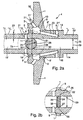
- Figure 1 a shows a rotationally symmetrical disc 1 with a through hole 2 and a Shaft 3, which together to a shaft-disc composite workpiece shown in Figures 1b and 1c 4 are to be joined together.
- the disc 1 points in the area of Through hole 2 two annular, the shaft 3 facing webs 5, 5 ', the one enclose annular recess 6.
- the shaft 3 points in a connection region 7 two stages 8,8 'on, the assembly of shaft 3 and disc 1 with the webs 5,5 'of the disc 1 are connected so that the step 8 with the web 5 and the step 8' with the bridge 5 'coincides.
- the inner diameter 9 of the web 5 is smaller by a Sch Strukturauerlapp 10 than that Outer diameter 11 of the stage 8, and the inner diameter 9 'of the web 5' is by one Weld overlap 10 'less than the outer diameter of the stage 8', so that shaft 3 and disc 1 before assembly in the region of these webs 5, 5 'or steps 8, 8' overlap radially.
- Disk 1 and shaft 3 are joined together by friction welding.
- the shaft 3 is set in rotation and axially moved so far in the direction of the (stationary) disc 1 until the steps 8,8 'of the shaft 3 with the webs 5,5 'of the disc 1 come into contact while a local heating cause the webs 5,5 'and the stages 8,8' in the mutual contact areas.
- shaft 3 and disc 1 typically exist made of steel materials.
- the friction welding also allows the joining of workpieces of different materials and in particular the joining hardened Joints. So can wave 3 and disc 1 made of different materials exist, or the shaft 3 can in the connection region 7 already before joining be hardened.
- Figures 1b and 1c show the welded shaft-disc composite piece 4, wherein the View of Figure 1c relative to the view of Figure 1b by 90 degrees about the shaft axis is turned.
- the shaft 3 is a solid shaft 15 which i.a. for the sake of weight saving is provided with two drilled interiors 16,16 '. Between the interiors 16,16 ' there is a divider 17, which separates the two interiors 16,16 'from each other and supported.
- the interior of the divider 17 is on the right 16 connected via an outlet opening 18 with the outer wall 14 of the shaft 3.
- the left the divider 17 located interior 16 ' is connected via a connecting hole 19 with the closed annular cavity 13 is connected, which in turn with an outlet opening 20 is provided to the outer wall 14 of the shaft 3.
- the two interiors 16,16, 'thus form parts of two independent, in the axial direction of the shaft 3 overlapping Media channels 21, 21 'in which e.g. Pressure oil can be performed.
- Media channels 21,21 ' can be connected fixed or axially displaceable.
- the Media channels 21,21 ' also to guide or distribute any other media such e.g. Lubricating oil, compressed air, cooling media, etc. along the shaft-disk composite 4 are used.
- FIG. 2 a shows a shaft-disk composite workpiece 4 which consists of a hollow shaft 22 Wave 3 and a disc 1 is built.
- Friction welding is - analogous to the embodiment shown in Figure 1 a - the outer wall 14 of the hollow shaft 22 is provided with two stages 8,8 ', with which the webs 5,5' of Disk 1 are connected.
- the steps 8, 8 'on the hollow shaft 22 may be formed by transverse rolling, Querf beaupressen or produced by machining the hollow shaft 22 become.
- the wall thickness of the hollow shaft 22 is low as possible.
- a support member 24 is so in the interior 25 of the hollow shaft 22 positioned that it the stage 8 - and thus the respect the friction welding the weakest point of the hollow shaft 22 - opposite.
- the Support member 24 prevents the hollow shaft 22 during friction welding in Range of level 8 bulges inward, thus ensuring that even with thin-walled Hollow shafts 22 the required friction forces for welding the steps 8,8 'on the shaft 3 and the webs 5, 5 'can be applied to the disk 1.
- Figure 2a shows an embodiment in which the support member 24 is formed as a ball 26 is, before the friction welding in the opposite of the stage 8 area 27th the interior 25 of the hollow shaft 22 is pressed.
- the outer diameter 28 of the ball 26 is in this case adapted to the inner diameter 29 of the hollow shaft 22.
- friction welding of the web 5 with the step 8 are caused by the plastic deformation of the relatively thin-walled hollow shaft 8 annular beads 30 in the vicinity of the pressed-in Ball 26, through which after the cooling of the shaft-disk-composite piece 4 a solid, tight fit of the ball 26 in the interior 25 of the hollow shaft 22 is effected.
- the interior 25 of the hollow shaft 22 is therefore by the ball 26 in two separate inner areas 16 and 16 'shared.
- the Support member 24 a cylindrical portion 33 having an inner diameter 29 of the hollow shaft 22 matched outer diameter 34, which before the friction welding in the stage 8th opposite region 27 of the interior 25 of the hollow shaft 22 is pressed.
- the Thickness of the cylinder piece 33 approximately equal to the thickness of the stage 8 to be joined Stegs 5 on the disc 1.
- the outer wall 35 of the cylindrical piece 33 is provided with a circumferential annular groove 36 provided in the by the plastic deformation of the hollow shaft 22 penetrates during the friction welding hollow shaft material and a tight fit of the cylinder piece 33 in the interior 25 of the hollow shaft 22 after cooling ensures.
- a further weight saving can be achieved if the cylinder piece 33 of a lightweight material, e.g. Aluminum, is made.
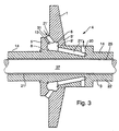
- FIG. 3 shows a further exemplary embodiment of a shaft-disk composite workpiece 4, consisting of a hollow shaft 22 and a disc 1.
- a rotating inner shaft 37 whose outer diameter is smaller is as the inner diameter of the Hohwelle 22, so that the inner shaft 37 against the Hollow shaft 22 can rotate without contact.
- Analogous to the example of Figure 1 b also has here the disc 1 two webs 5,5 ', in the area of which the disc 1 with the steps 8,8' the shaft 3 is connected. Between the webs 5,5 ', the disc has an annular Recess 6 on, by - after welding shaft 3 and disc 1 - a annular cavity 13 between the disc 1 and outer wall 14 of the hollow shaft 22 is formed becomes.
- the shaft-disk composite workpiece 4 has a media channel 21 ', the is designed analogously to the embodiment of Figure 2a and thus the inlet port 31st on the disc 1, the annular cavity 13 and the outlet opening 20 on the Hollow shaft 3 includes. If the interior 25 of the hollow shaft 22 is not for guiding an inner shaft 37 required, the interior 25 can also be used as a further media channel 21 by which e.g. Lubricating oil guided or distributed along the hollow shaft 22 becomes.
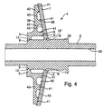
- FIG. 4 shows a shaft-disk composite workpiece 4 comprising a shaft 3 and a shaft Disc 1, wherein the disc 1 'shown here from a conical sheet metal plate 38th and a support frame 39.
- the support frame 39 comprises a rotationally symmetrical disc-shaped plate 40, of which a plurality of annular support ribs 41 approximately protrude in the axial direction and by friction welding with their opposite Rear wall 42 of the sheet metal plate 38 are connected.
- the sheet metal plate 38 consists of a high strength material which is insensitive to abrasive forces, e.g. from a Carbon steel.
- the support frame 39 for further weight savings made of a lightweight material, e.g. Aluminum, be made.
- a lightweight material e.g. Aluminum
- the so from sheet metal plates 38 and support frame 39 joined disc 1 ' has in the axis of rotation of the 3 shaft facing two annular webs 5, 5 ', wherein the one web 5 part of the support frame 39, while the other web 5 'through the axis near the area the sheet metal plate 38 is formed. Between the two webs 5,5 'is an annular Recess 6 before.
- the shaft 3 is provided with two steps 8,8 ', with which the webs 5,5' the disc 1 - analogous to the embodiments described above - by friction welding be connected to the steps 8,8 'of the shaft 3, wherein oblique joining zones 12 are formed.
- connection between shaft 3 and Disk 1 is formed by the connection of two webs 5,5 'with two stages 8,8', so that between the webs 5,5 'and steps 8,8', a single annular cavity 13 is formed, can in the general case, the shaft 3 and the disc 1 in the connection area. 7 have even more web-stage connections. This creates further annular Cavities 13, which lie between the disc 1 and the outer wall of the shaft 3.
Landscapes
- Engineering & Computer Science (AREA)
- Mechanical Engineering (AREA)
- General Engineering & Computer Science (AREA)
- Pressure Welding/Diffusion-Bonding (AREA)
Applications Claiming Priority (3)
| Application Number | Priority Date | Filing Date | Title |
|---|---|---|---|
| DE19934855A DE19934855C1 (de) | 1999-07-24 | 1999-07-24 | Reibgeschweißtes Welle-Scheibe-Verbundwerkstück und Verfahren zu seiner Herstellung |
| DE19934855 | 1999-07-24 | ||
| PCT/EP2000/005587 WO2001007200A1 (de) | 1999-07-24 | 2000-06-17 | Reibgeschweisstes welle-scheibe-verbundwerkstuck und verfahren zu seiner herstellung |
Publications (2)
| Publication Number | Publication Date |
|---|---|
| EP1198323A1 EP1198323A1 (de) | 2002-04-24 |
| EP1198323B1 true EP1198323B1 (de) | 2004-05-19 |
Family
ID=7915980
Family Applications (1)
| Application Number | Title | Priority Date | Filing Date |
|---|---|---|---|
| EP00942092A Expired - Lifetime EP1198323B1 (de) | 1999-07-24 | 2000-06-17 | Reibgeschweisstes welle-scheibe-verbundwerkstuck und verfahren zu seiner herstellung |
Country Status (6)
| Country | Link |
|---|---|
| US (1) | US6660407B1 (enExample) |
| EP (1) | EP1198323B1 (enExample) |
| JP (1) | JP2003505249A (enExample) |
| DE (1) | DE19934855C1 (enExample) |
| ES (1) | ES2219355T3 (enExample) |
| WO (1) | WO2001007200A1 (enExample) |
Cited By (1)
| Publication number | Priority date | Publication date | Assignee | Title |
|---|---|---|---|---|
| CN104936739A (zh) * | 2013-01-21 | 2015-09-23 | 麦格纳动力系有限两合公司 | 包括进行摩擦焊接的毂和轴或齿轮的接合部位设计 |
Families Citing this family (12)
| Publication number | Priority date | Publication date | Assignee | Title |
|---|---|---|---|---|
| JP4396803B2 (ja) * | 2001-05-15 | 2010-01-13 | トヨタ自動車株式会社 | 中空製品の製造方法、およびその製造装置 |
| DE10336668A1 (de) * | 2003-08-09 | 2005-02-24 | Daimlerchrysler Ag | Fügestellenstruktur für ein Reibschweißverfahren und Verfahren zu deren Herstellung |
| JP4385373B2 (ja) * | 2003-12-25 | 2009-12-16 | オリジン電気株式会社 | 溶接物品及び金属部品の溶接方法 |
| DE102005029539A1 (de) * | 2005-06-25 | 2006-12-28 | Daimlerchrysler Ag | Achsschenkel für ein Kraftfahrzeug |
| US20080000558A1 (en) * | 2006-06-30 | 2008-01-03 | Nan Yang | Friction welding |
| DE102006053790A1 (de) * | 2006-11-15 | 2008-05-21 | Volkswagen Ag | Verfahren zum Fügen eines Schaltrades mit einem Kupplungskörper, sowie Fügestellenstruktur |
| US7726542B2 (en) * | 2008-06-25 | 2010-06-01 | Gm Global Technology Operations, Inc. | Friction-welded assembly with interlocking feature and method for forming the assembly |
| GB0913655D0 (en) * | 2009-08-06 | 2009-09-16 | Rolls Royce Plc | A method of friction welding |
| DE102011000544A1 (de) * | 2011-02-07 | 2012-08-09 | Gesenkschmiede Schneider Gmbh | Verfahren zur Herstellung eines reibgeschweissten Metallteils und danach hergestelltes reibgeschweisstes Metallteil |
| JP6150662B2 (ja) * | 2013-08-12 | 2017-06-21 | シチズン時計株式会社 | 回転軸体 |
| US20170198592A1 (en) * | 2016-01-11 | 2017-07-13 | General Electric Company | Methods for mounting a turbine subcomponent to a turbine component |
| DE102016005464A1 (de) | 2016-05-06 | 2017-11-09 | lFA-Technologies GmbH | Fügestellenstruktur für durch Reibschweißen zu verbindende Bauteile und Verfahren zum Verbinden von Bauteilen durch Reibschweißen |
Family Cites Families (23)
| Publication number | Priority date | Publication date | Assignee | Title |
|---|---|---|---|---|
| US3631585A (en) * | 1966-10-17 | 1972-01-04 | North American Rockwell | Method of making a friction-welded drive axle shaft having an annular section of flash metal |
| US4087038A (en) * | 1975-12-19 | 1978-05-02 | Harima Sargyo Kabushiki Kaisha | Frictional welding method |
| DE2735074C2 (de) | 1977-08-04 | 1982-10-28 | Kuka Schweissanlagen + Roboter Gmbh, 8900 Augsburg | Werkstück, bestehend aus zwei im Rotations-Reibschweißverfahren verbundenen Werkteilen |
| DE2848355C2 (de) * | 1978-11-08 | 1983-08-25 | Deutsche Forschungs- und Versuchsanstalt für Luft- und Raumfahrt e.V., 5300 Bonn | Wellen-Naben-Verbindung |
| DE3268013D1 (en) * | 1981-08-18 | 1986-01-30 | Bbc Brown Boveri & Cie | Exhaust-gas turbocharger with bearings between turbine and compressor |
| US4850802A (en) * | 1983-04-21 | 1989-07-25 | Allied-Signal Inc. | Composite compressor wheel for turbochargers |
| US4872817A (en) * | 1984-07-19 | 1989-10-10 | Allied-Signal Inc. | Integral deflection washer compressor wheel |
| DE3545135A1 (de) * | 1984-12-19 | 1986-06-26 | Honda Giken Kogyo K.K., Tokio/Tokyo | Fittingeinheit |
| JPS62191478A (ja) * | 1986-02-19 | 1987-08-21 | 日本碍子株式会社 | セラミツクス・金属結合体 |
| US4982826A (en) * | 1988-04-29 | 1991-01-08 | Chrysler Corporation | Bleeder ball check valves in an automatic transmission |
| DE3834080A1 (de) * | 1988-10-04 | 1990-04-05 | Mannesmann Ag | Verfahren zur befestigung eines im wesentlichen scheibenfoermigen, rotationssymmetrischen metallischen formkoerpers auf einer metallischen welle |
| JPH0818151B2 (ja) * | 1988-11-11 | 1996-02-28 | 大同特殊鋼株式会社 | Ti−Al合金と構造用鋼との接合方法および接合部品 |
| DE4116088A1 (de) * | 1991-05-16 | 1992-11-19 | Forschungszentrum Juelich Gmbh | Verfahren zum verbinden von stahl mit aluminium- bzw. titanlegierungsteilen und danach erhaltene turbolader |
| JPH05155668A (ja) * | 1991-12-09 | 1993-06-22 | Ngk Spark Plug Co Ltd | セラミックスと金属との結合体 |
| US5205464A (en) * | 1991-12-19 | 1993-04-27 | Joseph Simon | Method for forming a lightweight flanged axle shaft |
| US5248078A (en) * | 1992-03-27 | 1993-09-28 | United Technologies Corporation | Inertia bonding of long shafts |
| GB9226489D0 (en) * | 1992-12-19 | 1993-02-10 | Univ Manchester | A joint |
| DE4305102A1 (de) * | 1993-02-19 | 1994-08-25 | Zahnradfabrik Friedrichshafen | Einrichtung zur Führung einer beweglichen Scheibe |
| US5431752A (en) * | 1993-11-12 | 1995-07-11 | Asea Brown Boveri Ltd. | Friction welding of γ titanium aluminide to steel body with nickel alloy connecting piece there between |
| DE19519576B4 (de) | 1995-05-29 | 2004-07-08 | Steyr-Daimler-Puch Ag | Geschweißter Achskörper |
| JP3403572B2 (ja) * | 1996-03-08 | 2003-05-06 | 株式会社日立ユニシアオートモティブ | 等速自在継手 |
| JP3453302B2 (ja) * | 1998-05-07 | 2003-10-06 | 三菱重工業株式会社 | TiAl合金部材と構造用鋼材との接合方法及び接合部品 |
| US6065813A (en) * | 1998-08-24 | 2000-05-23 | Dana Corporation | Two-piece friction welded motor vehicle axle shaft |
-
1999
- 1999-07-24 DE DE19934855A patent/DE19934855C1/de not_active Expired - Fee Related
-
2000
- 2000-06-17 WO PCT/EP2000/005587 patent/WO2001007200A1/de not_active Ceased
- 2000-06-17 JP JP2001512063A patent/JP2003505249A/ja active Pending
- 2000-06-17 EP EP00942092A patent/EP1198323B1/de not_active Expired - Lifetime
- 2000-06-17 ES ES00942092T patent/ES2219355T3/es not_active Expired - Lifetime
- 2000-06-17 US US10/031,748 patent/US6660407B1/en not_active Expired - Fee Related
Cited By (2)
| Publication number | Priority date | Publication date | Assignee | Title |
|---|---|---|---|---|
| CN104936739A (zh) * | 2013-01-21 | 2015-09-23 | 麦格纳动力系有限两合公司 | 包括进行摩擦焊接的毂和轴或齿轮的接合部位设计 |
| US10060482B2 (en) | 2013-01-21 | 2018-08-28 | Magna Powertrain Ag & Co Kg | Joint-site design comprising a hub and a shaft or a gear being friction welded |
Also Published As
| Publication number | Publication date |
|---|---|
| EP1198323A1 (de) | 2002-04-24 |
| US6660407B1 (en) | 2003-12-09 |
| DE19934855C1 (de) | 2000-11-09 |
| JP2003505249A (ja) | 2003-02-12 |
| WO2001007200A1 (de) | 2001-02-01 |
| ES2219355T3 (es) | 2004-12-01 |
Similar Documents
| Publication | Publication Date | Title |
|---|---|---|
| EP1198323B1 (de) | Reibgeschweisstes welle-scheibe-verbundwerkstuck und verfahren zu seiner herstellung | |
| DE69905815T2 (de) | Gehäuse für Kraftfahrzeug- Ausgleichsgetriebe | |
| DE102008026695B4 (de) | Differentialgetriebeanordnung | |
| DE69901373T2 (de) | Herstellungsverfahren für Kraftfahrzeug- Ausgleichsgetriebe | |
| DE10352963B4 (de) | Wandler | |
| DE69901141T2 (de) | Herstellungsverfahren für Kraftfahrzeug- Ausgleichsgetriebe | |
| DE10013429C1 (de) | Ausgleichgetriebe | |
| DE69624767T2 (de) | Zweimassen-Schwungrad | |
| EP1851459B1 (de) | Kreuzgelenk | |
| DE4038122C2 (de) | Antriebswellen-Anordnung | |
| DE202019004569U1 (de) | Arbeitszylinder | |
| EP1320689B1 (de) | Geschweisstes bundlager, verfahren zur herstellung von geschweissten bundlagern und vorrichtung zur durchführung des verfahrens | |
| DE4107222C2 (de) | Verbindung zwischen einer rohrförmigen Welle aus einem Faserverbundwerkstoff und einem Metallzapfen, sowie Verfahren zu ihrer Herstellung | |
| EP1250210B1 (de) | Verfahren zum verbinden zweier teile mittels reibschweissung und nach diesem verfahren hergestelltes maschinenelement | |
| DE102004041084B4 (de) | Gelenklager | |
| DE102004043337B4 (de) | Querdifferential eines Kraftfahrzeuges sowie Herstellungsverfahren desselben | |
| DE3302762A1 (de) | Verfahren zur befestigung eines bauteils am aussenumfang eines rohrs | |
| WO1986004126A1 (fr) | Dispositif conçu pour absorber les vibrations | |
| DE10029317A1 (de) | Verfahren zur Herstellung eines Drehschwingungsdämfergehäuses, insbesondere eines Gehäuses für einen Viskositätsdrehschwingungsdämpfer | |
| EP2601388A1 (de) | Mehrteiliges turboladergehäuse | |
| EP2219819B1 (de) | Verfahren zum herstellen eines integral beschaufelten rotors | |
| EP2379909B1 (de) | Torsionsschwingungsdämpfer mit einer primärseite und verfahren zum herstellen einer primärmasse eines torsionsschwingungsdämpfers | |
| DE4300869A1 (de) | Drehschwingungsdämpfer, insbesondere für Kraftfahrzeuge | |
| EP4055282B1 (de) | Kolbeneinheit für einen arbeitszylinder | |
| DE2005080A1 (de) | Drehschwingungsdämpfer und Verfahren zu seiner Herstellung |
Legal Events
| Date | Code | Title | Description |
|---|---|---|---|
| PUAI | Public reference made under article 153(3) epc to a published international application that has entered the european phase |
Free format text: ORIGINAL CODE: 0009012 |
|
| 17P | Request for examination filed |
Effective date: 20020112 |
|
| AK | Designated contracting states |
Kind code of ref document: A1 Designated state(s): AT BE CH CY DE DK ES FI FR GB GR IE IT LI LU MC NL PT SE |
|
| AX | Request for extension of the european patent |
Free format text: AL;LT;LV;MK;RO;SI |
|
| GRAP | Despatch of communication of intention to grant a patent |
Free format text: ORIGINAL CODE: EPIDOSNIGR1 |
|
| GRAS | Grant fee paid |
Free format text: ORIGINAL CODE: EPIDOSNIGR3 |
|
| GRAA | (expected) grant |
Free format text: ORIGINAL CODE: 0009210 |
|
| AK | Designated contracting states |
Kind code of ref document: B1 Designated state(s): ES FR GB IT |
|
| REG | Reference to a national code |
Ref country code: GB Ref legal event code: FG4D Free format text: NOT ENGLISH |
|
| REG | Reference to a national code |
Ref country code: IE Ref legal event code: FG4D Free format text: GERMAN |
|
| GBT | Gb: translation of ep patent filed (gb section 77(6)(a)/1977) |
Effective date: 20040716 |
|
| LTIE | Lt: invalidation of european patent or patent extension |
Effective date: 20040519 |
|
| REG | Reference to a national code |
Ref country code: ES Ref legal event code: FG2A Ref document number: 2219355 Country of ref document: ES Kind code of ref document: T3 |
|
| REG | Reference to a national code |
Ref country code: IE Ref legal event code: FD4D |
|
| ET | Fr: translation filed | ||
| PLBE | No opposition filed within time limit |
Free format text: ORIGINAL CODE: 0009261 |
|
| STAA | Information on the status of an ep patent application or granted ep patent |
Free format text: STATUS: NO OPPOSITION FILED WITHIN TIME LIMIT |
|
| 26N | No opposition filed |
Effective date: 20050222 |
|
| PGFP | Annual fee paid to national office [announced via postgrant information from national office to epo] |
Ref country code: GB Payment date: 20050606 Year of fee payment: 6 |
|
| PGFP | Annual fee paid to national office [announced via postgrant information from national office to epo] |
Ref country code: FR Payment date: 20050610 Year of fee payment: 6 |
|
| PGFP | Annual fee paid to national office [announced via postgrant information from national office to epo] |
Ref country code: ES Payment date: 20050616 Year of fee payment: 6 |
|
| PG25 | Lapsed in a contracting state [announced via postgrant information from national office to epo] |
Ref country code: GB Free format text: LAPSE BECAUSE OF NON-PAYMENT OF DUE FEES Effective date: 20060617 |
|
| PG25 | Lapsed in a contracting state [announced via postgrant information from national office to epo] |
Ref country code: ES Free format text: LAPSE BECAUSE OF NON-PAYMENT OF DUE FEES Effective date: 20060619 |
|
| PGFP | Annual fee paid to national office [announced via postgrant information from national office to epo] |
Ref country code: IT Payment date: 20060630 Year of fee payment: 7 |
|
| GBPC | Gb: european patent ceased through non-payment of renewal fee |
Effective date: 20060617 |
|
| REG | Reference to a national code |
Ref country code: FR Ref legal event code: ST Effective date: 20070228 |
|
| REG | Reference to a national code |
Ref country code: ES Ref legal event code: FD2A Effective date: 20060619 |
|
| PG25 | Lapsed in a contracting state [announced via postgrant information from national office to epo] |
Ref country code: FR Free format text: LAPSE BECAUSE OF NON-PAYMENT OF DUE FEES Effective date: 20060630 |
|
| PG25 | Lapsed in a contracting state [announced via postgrant information from national office to epo] |
Ref country code: IT Free format text: LAPSE BECAUSE OF NON-PAYMENT OF DUE FEES Effective date: 20070617 |