EP1197918A2 - Freigeformtes Modellierungsverfahren und -System - Google Patents
Freigeformtes Modellierungsverfahren und -System Download PDFInfo
- Publication number
- EP1197918A2 EP1197918A2 EP01203693A EP01203693A EP1197918A2 EP 1197918 A2 EP1197918 A2 EP 1197918A2 EP 01203693 A EP01203693 A EP 01203693A EP 01203693 A EP01203693 A EP 01203693A EP 1197918 A2 EP1197918 A2 EP 1197918A2
- Authority
- EP
- European Patent Office
- Prior art keywords
- user
- geometry
- graphic tools
- command
- receiving input
- Prior art date
- Legal status (The legal status is an assumption and is not a legal conclusion. Google has not performed a legal analysis and makes no representation as to the accuracy of the status listed.)
- Ceased
Links
Images


Classifications
-
- G—PHYSICS
- G06—COMPUTING OR CALCULATING; COUNTING
- G06F—ELECTRIC DIGITAL DATA PROCESSING
- G06F30/00—Computer-aided design [CAD]
- G06F30/10—Geometric CAD
- G06F30/12—Geometric CAD characterised by design entry means specially adapted for CAD, e.g. graphical user interfaces [GUI] specially adapted for CAD
-
- G—PHYSICS
- G06—COMPUTING OR CALCULATING; COUNTING
- G06T—IMAGE DATA PROCESSING OR GENERATION, IN GENERAL
- G06T19/00—Manipulating three-dimensional [3D] models or images for computer graphics
- G06T19/20—Editing of three-dimensional [3D] images, e.g. changing shapes or colours, aligning objects or positioning parts
-
- G—PHYSICS
- G06—COMPUTING OR CALCULATING; COUNTING
- G06F—ELECTRIC DIGITAL DATA PROCESSING
- G06F30/00—Computer-aided design [CAD]
-
- G—PHYSICS
- G06—COMPUTING OR CALCULATING; COUNTING
- G06F—ELECTRIC DIGITAL DATA PROCESSING
- G06F2111/00—Details relating to CAD techniques
- G06F2111/04—Constraint-based CAD
-
- G—PHYSICS
- G06—COMPUTING OR CALCULATING; COUNTING
- G06T—IMAGE DATA PROCESSING OR GENERATION, IN GENERAL
- G06T2200/00—Indexing scheme for image data processing or generation, in general
- G06T2200/24—Indexing scheme for image data processing or generation, in general involving graphical user interfaces [GUIs]
-
- G—PHYSICS
- G06—COMPUTING OR CALCULATING; COUNTING
- G06T—IMAGE DATA PROCESSING OR GENERATION, IN GENERAL
- G06T2219/00—Indexing scheme for manipulating 3D models or images for computer graphics
- G06T2219/20—Indexing scheme for editing of 3D models
- G06T2219/2021—Shape modification
Definitions
- the present invention relates to the field computer-aided design (CAD), computer aided manufacturing (CAM), and computer aided engineering (CAE), and more particularly to systems and methods for performing freeform modeling operations in this field.
- CAD computer-aided design
- CAM computer aided manufacturing
- CAE computer aided engineering
- the stylists interactively work on the patches through a set of commands, such as the Control Point Modification command, the Matching command, the Extrapolation command and the Offset command, until the resulting overall shape of the surface is found satisfactory from an aesthetic viewpoint, according to engineering constraints such as accuracy and technical feasibility.
- a modification to the geometry of one patch usually impacts other parts of the geometry.
- the user does not know in advance the overall or global effect of a local modification to a patch. Therefore, to arrive at a final design that satisfies not only the design requirements for each patch, but also satisfies the design requirements for the overall surface, the user must engage in an iterative optimization sequence by manually alternating between individual commands. This work requires hundreds, if not thousands, of commands and iterations per workday.
- the present invention provides a system, method, and apparatus for providing greatly increased productivity in freeform modeling.
- this is accomplished by providing a framework by which arbitrary (including overlapping) portions of the geometry of a design can be marked so that multiple command functions for manipulating the geometry, each of which are associated with a portion of the design, will be concurrently active.
- the system displays representations of the commands in the form of interactive tools or handles, which can be manipulated by the user. For example, upon a user's selection of a patch and of the Control Point Modification command, the system will display a grid of control points over the selected patch. Further selection of an adjacent patch and of a Matching command will result in the system displaying an arrow linking the original patch and the adjacent patch.
- These multiple commands are concurrently active and can be directly run by the user through manipulation of the corresponding interactive tools.
- the system Upon a user manipulation of one of the tools, the system will, as is commonly known, determine the effect of the manipulation on the geometry and display the modified geometry. According to the invention, the system also determines if the modification impacts on other active commands and, if so, the system updates the representations of the tools related to such commands. Commands that are concurrently active on arbitrary portions of the design are referred to as parallel commands.
- the system allows the user to declare one or more commands as associative.
- a command is designated as associative, it is launched automatically with each modification of its related geometry that is caused by any other active command. Obviously, this saves additional mouse clicks. But it becomes of higher importance during dynamic interactions which are typical for surface modeling. For example, with each single control point movement (pixel-wise) all associative declared commands are updated immediately; that is, the user is in control of the global behavior of his local modifications at any time (even during dynamic interactions, which is not given in known freeform modeling applications).
- This aspect of the invention greatly facilitates the iterative design process, by reducing substantially the number of manual steps that a designer must perform.
- the user may store the interactive scene as it is at any given time, with the current selections and tool representations, so that the work can be resumed later without the user having to redo any interactions.
- the system allows the user to capture all design constraints and dependencies throughout the whole lifetime of a design model.
- the user may save the "how" of his modification, which means, how the result has been achieved. (Note that with this kind of User Interface storage, the system enters the 4th (time) dimension of User Interfaces in general).
- Such saved interactive scenes may cover (and overlap) the whole design model and can be resumed later at any given time, with all stored commands, their parameters, tool representations and selected elements, so that the user can resume his work immediately without having to redo any interactions.
- the user can map a given scene onto a similar design model. This would result in copying and pasting design constraints and dependencies on the new model, and re-applying all interactions of the scene on the new model.
- a command can be declared as implicit, which is related to its selection request. Whenever such a command is launched, each geometry of currently active commands that meets the specific selection criteria becomes automatically part of the selection. The same is true for any newly created geometry as long as the implicit command stays active.
- users can add or remove commands and related tools to or from the list of active commands at any time. Users can also request the system to hide some of the tools or to show them.
- users can add or remove elements to or from the command-specific list of selected entities.
- the designation of a command as associative can be turned on and off at user's request at any time.
- some tolerancing can be included in the execution of an associative command, in which case the execution will be considered successful if the result remains within the defined tolerance.
- the system advises the user accordingly, by a change in the visual representation of the related tool.
- the system may be organized so that it executes the associative commands in a predefined sequence to minimize the risk of disturbance of potentially shared geometry.
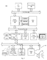
- the computer 100 has a central processor 101 connected to a processor host bus 102 over which it provides data, address and control signals.
- the processors 101 may be any conventional general-purpose single-chip or multi-chip microprocessor such as a Pentium® series processor, a K6 processor, a MIPS® processor, a Power PC® processor or an ALPHA® processor.
- the processor 101 may be any conventional special purpose microprocessor such as a digital signal processor or a graphics processor.
- the microprocessor 101 can have conventional address, data, and control lines coupling it to a processor host bus 102.
- the computer 100 can include a system controller 103 having an integrated RAM memory controller 104.
- the system controller 103 can be connected to the host bus 102 and provide an interface to random access memory 105.
- the system controller 103 can also provide host bus to peripheral bus bridging functions.
- the controller 103 can thereby permit signals on the processor host bus 102 to be compatibly exchanged with signals on a primary peripheral bus 110.
- the peripheral bus 110 may be, for example, a Peripheral Component Interconnect (PCI) bus, an Industry Standard Architecture (ISA) bus, or a Micro-Channel bus.
- PCI Peripheral Component Interconnect
- ISA Industry Standard Architecture
- Micro-Channel bus Micro-Channel bus
- the controller 103 can thereby allow, for example, a processor 101 having a 64-bit 66 MHz interface and a 533 Mbytes/second data transfer rate to interface to a PCI bus 110 having a data path differing in data path bit width, clock speed, or data transfer rate.
- Accessory devices including, for example, a hard disk drive control interface 111 coupled to a hard disk drive 113, a video display controller 112 coupled to a video display 115, and a keyboard and mouse controller 121 can be coupled to a bus 120 and controlled by the processor 101.
- the computer system can include a connection to a computer system network, an intranet or an internet. Data and information may be sent and received over such a connection.
- the computer 100 can also include nonvolatile ROM memory 122 to store basic computer software routines.
- ROM 122 may include alterable memory, such as EEPROM (Electronically Erasable Programmable Read Only Memory), to store configuration data.
- BIOS routines 123 can be included in ROM 122 and provide basic computer initialization, systems testing, and input/output (I/O) services.
- the BIOS 123 can also include routines that allow an operating system to be "booted" from the disk 113. Examples of high-level operating systems are, the Microsoft Windows 98TM, Windows NTTM, Windows 2000TM,UNIX, LINUX, the Apple MacOS TM operating system, or other operating system.
- An operating system may be fully loaded in the RAM memory 105 or may include portions in RAM memory 105, disk drive storage 113, or storage at a network location.
- the operating system can provide functionality to execute software applications, software systems and tools of software systems.
- Software functionality can access the video display controller 112 and other resources of the computer system 100 to provide models of objects on the video computer display 115.
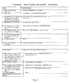
- the modeling process is listed as single steps in a table with two columns.
- the left column describes user actions, and the right column describes the action of the main components in the CAD system.
- the example starts with two Bezier surface patches with one common edge and activated section and curvature analysis on these patches.
- the goal is to move the common edge around 100 mm to the left and create a G3 (smooth curvature) transition.
- the matching function can only achieve a G2 (same curvature) transition (in this example).
- G3 transition the third control point row (counted beginning at the common edge) is moved interactively combined with an activation of the G2 matching.
- the matching function is associative. Only the third control point row needs to be moved, the matching is recalled on every interactive dynamic step. So the user sees the final result and can adjust the control point row directly.
- the first step in the process is the extrapolation of patch 1 to the left. This is done in steps 1-3 of the table. Patch 2 is then matched to patch 1 in steps 4-8. In accomplishing steps 1-8, the user must perform many operations, since in most cases the user must quit a current command to launch a new command, and must select an object for each command.
- the matching function can only achieve a G2 transition.
- the third control point row In order to achieve a G3 transition, the third control point row must be moved. This action must be followed by another matching command.
- the user since the user does not know precisely what design will be achieved by those two combined steps, the user must simply make a guess each time he moves the third control point row of patch 2, and hope that the subsequent match will achieve a satisfactory design. Only through several iterations can a designer achieve a satisfactory result. Of course, each iteration requires many steps by the user for the activation and deactivation of commands, selection of objects, etc. As indicated in Fig. 2, each of steps 9-15 must be repeated until a satisfactory result is achieved.
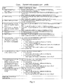
- Fig. 3 depicts an embodiment of the present invention in which parallel commands are used. In this case, the number of steps required by the user is substantially reduced.
- a comparison of Figs. 2 and 3 shows that whereas in Fig. 2, each iteration (involving the movement of the third control point row followed by a matching command) requires seven steps (steps 9-15), with parallel commands the same iteration requires only two steps (steps 11-12).
- Fig. 3 Focusing on Fig. 3, it can be seen that the user is able to set up the system so that the commands he wishes to use remain active, and remain linked to the desired patches.
- the control point command is made active and patches 1 and 2 are marked as objects of the command.
- the 3D handles associated with each command are designated for automatic update each time the geometry associated with the handle changes.
- the matching command is active, with patch 1 designated as reference and patch 2 as modified, and the 3D handles are designated for automatic update.
- the extrapolation command is activated for patch 1, and the corresponding 3D handle designated for update.
- step 9 when the extrapolation of patch 1 is done by the user in step 9, the matching, control point modification, and extrapolation 3D handles are automatically adjusted to fit the modified geometry. And in step 10, the user need only activate the matching handle of patch 2 to perform a match of patch 2 to patch 1. The 3D handles are automatically updated.
- the movement of the third control point row of patch 2 must be followed by a match of patch 2 to patch 1 in iterative fashion in order to achieve a G3 transition.
- this requires only two operations by the user. The user moves the third control point row of patch 2 in step 11, and when he does so the 3D handles and geometry are automatically updated. He then simply activates matching, and again the geometry and 3D handles are automatically updated.
- the iterative portion of the design process is much easier and less time consuming to accomplish.
- Fig. 4 the system of the invention using both parallel and associative commands is depicted. In this case, the number of steps required by the user is reduced even further. In this system, the iteration required for achieving a satisfactory design with a G3 transition (involving the movement of the third control point row followed by a matching command) requires repeating just one step (step 10), i.e., moving the third control point row of patch 2. All other necessary steps are performed automatically.
- step 4 the matching command is also designated as being "associative," which means that it will be launched automatically with each modification of the geometry to which it is related. In this case, any time patch I is modified, the matching command will automatically match patch 2 to patch 1. Therefore, in step 9, when the user extrapolates patch 1 by moving the extrapolation handle of patch 1, patch 2 is automatically matched to patch 1. More significantly, when the user in step 10 moves the third control point row of patch 2, patch 2 is then automatically re-matched to patch 1 without any further action by the user. Therefore, the user can simply continue to move the third control point row until a suitable G3 transition is achieved. No further steps are required.
- the system allows the user to save the design at any stage, so the user can leave a project, and later resume the project without repeating any steps. Focusing on Fig. 4, for example, the user could stop after completing step 8, and return later, picking up at step 9, without having to redo any of steps. This is depicted in Fig. 5, where the user reactivates an already setup scene from an earlier session.
- the example illustrates the vast improvement in productivity that is achieved with the present invention.
- FIG. 6 A process for updating the parallel and associative commands according to a preferred embodiment of the invention is depicted in Fig. 6.
- the command related to the handle is executed by manipulating the geometry element or elements related to the handle, and the 3D handle is marked for update (step 51).
- Updating a 3D handle is accomplished by the system by moving the 3D handle so that it maintains its position with respect to the geometry. Since the geometry has been modified, the 3D handle must be moved also.
- step 52 The update process is then begun (step 52), and the system looks for marked geometry (step 53). If one is found, then the system looks for a command on the marked geometry (step 55). If a command is found, a query is made as to whether the command is associative (step 61). If it is not, then the 3D handle for the command on the geometry in question is updated (step 62), and the system looks for the next command on the geometry (step 55). If, in step 61, it is determined that the command is associative, then the system checks to see if the command has already been performed with respect to the geometry in question in any iteration (step 63).
- step 64, no If so, (step 64, no), then the command is not performed again; instead the 3D handle is updated just as if the command were not associative. However, if the command has not yet been performed (step 64, yes), then the command is performed on the appropriate geometry (step 65), the geometry is flagged to indicate that the command has already been performed (step 66), the geometry on which the command has been performed is marked for the next iteration (step 66), and the 3D handle is updated (step 62). The process is repeated for each command on the marked geometry until all commands have been processed, in which case no more commands will be found (step 60, no). The system will then check for the next marked geometry (step 53), and if one is found all commands for that geometry will be processed as indicated above.
- step 54 If no further marked geometries are found (step54, no), then the system checks for geometry that has been marked for the next iteration (step 56). If one is found, then the process begins for the next iteration, (step 58). Otherwise, the update process is complete (steps 57, 59), to begin again in the event that the user moves a 3D handle.
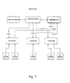
- Fig. 7 is a global view of the structure of the system of the present invention.
- Parallel and associative commands are managed by the main command assisted by the geometry slot and the selection agency.
- the main command handles and administers all individual command interactions, serves parallel commands with update events and asks associative commands to re-run if necessary.
- a centralized geometry access to avoid data overwriting
- a global update mechanism to update 3D handles
- Each individual command is mainly controlled by the user through 3D handles on the geometry elements.
- manipulation of the 3D handles for example by positioning a cursor over the handle, clicking a mouse to activate the handle, and moving the handle, typically causes a change in the geometry of the patch to which the handle is related.
- many different 3D handles may be visible on geometry elements in the 3D view.
- the implementation must give a unique look for 3D handles dedicated for a specific command, so the user directly associates a 3D handle to functionality, implemented through a specific command. Therefore one general rule exists, namely, that each specific 3D handle is dedicated to one and only one specific command.
- each geometry element may be accessed by different commands at the same time.
- 3D handles are geometric User Interface objects, which may be directly manipulated by the user (like buttons and sliders in a 2D panel dialog). Each movement event of a handle is sent to the related individual command, which manipulates the underlying geometry element (or elements) accordingly to its functionality.
- An individual command reacts on 3D handle modifications and changes the geometry data accessed through the common geometry slot accordingly to its specific functionality. It then activates the general update process of the main command. This is done on each interactive step (on each movement event of the mouse or other possible input devices).
- An individual command may also act as a server for the main command, i.e., update 3D handles, and re-run the command if flagged as associative.
- update 3D handles i.e., update 3D handles
- re-run the command if flagged as associative.
- those interface functions access the geometry through the common geometry slot, described below.
- the geometry slot is a large table of all selected geometry elements for all active commands. For each geometry element it stores a list of commands that have been associated with the geometry element, and a set of flags showing the state of the geometry element with respect to each command associated with the element.
- the geometry slot also contains a table of all active commands. For each command it stores the command identifier and the attributes of the command, i.e., whether it is associative or not.
- the Geometry Slot has mainly two classes of interface functions: 1) add, remove, or modify geometry elements (modify the geometry table), and 2) iterative and direct access functions for all individual commands and for the general update process of the main command.
- the selection agency serves all user selection for all individual commands. Individual commands only distribute so-called selection requests to the selection agency, which keep the information of the command identifier of the calling command, the geometry type, the number of requested elements and other attributes for the selection agency to set up an interactive selection mode. Selection requests are also used to store results of the selection and will be used by the geometry slot for adding geometry elements. Although the selection agency is shown in Fig. 7 conceptually as separate from the main command, it can be thought of as part of the main command, serving an administrative function.
- the main command is responsible for the lifetime of all individual commands, the initialization of the geometry slot, and entering the results of the selection from the selection agency into the geometry slot.
- the main interface function (related to this invention) is the global update function, initiated by each individual command on each dynamic step.
- the global update function is the main service function to ensure that parallel commands work well together, especially if individual commands work on the same geometry. Also it ensures, that associative commands are recalled to related geometry changes.
- the foregoing method can be applied to any system for designing objects, including any CAD/CAM/CAE system.
- the invention may be implemented in digital electronic circuitry, or in computer hardware, firmware, software, or in combinations of them.
- Apparatus of the invention may be implemented in a computer program product tangibly embodied in a machine-readable storage device for execution by a programmable processor; and method steps of the invention may be performed by a programmable processor executing a program of instructions to perform functions of the invention by operating on input data and generating output.
- the invention may advantageously be implemented in one or more computer programs that are executable on a programmable system including at least one programmable processor coupled to receive data and instructions from, and to transmit data and instructions to, a data storage system, at least one input device, and at least one output device.
- the application program may be implemented in a high-level procedural or object-oriented programming language, or in assembly or machine language if desired; and in any case, the language may be a compiled or interpreted language.
- a processor will receive instructions and data from a read-only memory and/or a random access memory.
- Storage devices suitable for tangibly embodying computer program instructions and data include all forms of nonvolatile memory, including by way of example semiconductor memory devices, such as EPROM, EEPROM, and flash memory devices; magnetic disks such as internal hard disks and removable disks; magneto-optical disks; and CD-ROM disks. Any of the foregoing may be supplemented by, or incorporated in, specially designed ASICs (application-specific integrated circuits).
- ASICs application-specific integrated circuits
Landscapes
- Engineering & Computer Science (AREA)
- Physics & Mathematics (AREA)
- Theoretical Computer Science (AREA)
- General Physics & Mathematics (AREA)
- General Engineering & Computer Science (AREA)
- Computer Hardware Design (AREA)
- Geometry (AREA)
- Architecture (AREA)
- Evolutionary Computation (AREA)
- Software Systems (AREA)
- Computer Graphics (AREA)
- Human Computer Interaction (AREA)
- Computational Mathematics (AREA)
- Mathematical Analysis (AREA)
- Mathematical Optimization (AREA)
- Pure & Applied Mathematics (AREA)
- Processing Or Creating Images (AREA)
Applications Claiming Priority (2)
| Application Number | Priority Date | Filing Date | Title |
|---|---|---|---|
| US680774 | 2000-10-06 | ||
| US09/680,774 US7003363B1 (en) | 2000-10-06 | 2000-10-06 | Freeform modeling method and system |
Publications (2)
| Publication Number | Publication Date |
|---|---|
| EP1197918A2 true EP1197918A2 (de) | 2002-04-17 |
| EP1197918A3 EP1197918A3 (de) | 2004-05-19 |
Family
ID=24732465
Family Applications (1)
| Application Number | Title | Priority Date | Filing Date |
|---|---|---|---|
| EP01203693A Ceased EP1197918A3 (de) | 2000-10-06 | 2001-09-28 | Freigeformtes Modellierungsverfahren und -System |
Country Status (4)
| Country | Link |
|---|---|
| US (1) | US7003363B1 (de) |
| EP (1) | EP1197918A3 (de) |
| JP (1) | JP3760123B2 (de) |
| CA (1) | CA2357978C (de) |
Cited By (3)
| Publication number | Priority date | Publication date | Assignee | Title |
|---|---|---|---|---|
| WO2006131834A3 (en) * | 2005-06-07 | 2007-05-18 | Toyota Motor Co Ltd | Model creation support system and method |
| RU2308763C2 (ru) * | 2005-09-26 | 2007-10-20 | Государственное унитарное предприятие "Конструкторское бюро приборостроения" | Способ автоматического построения трехмерной геометрической модели изделия в системе геометрического моделирования |
| RU2542160C1 (ru) * | 2013-12-25 | 2015-02-20 | Общество с ограниченной ответственностью "Нефтекамский машиностроительный завод" (ООО "НКМЗ") | Способ проектирования центробежных насосов |
Families Citing this family (1)
| Publication number | Priority date | Publication date | Assignee | Title |
|---|---|---|---|---|
| US20070239696A1 (en) * | 2006-03-28 | 2007-10-11 | Microsoft Corporation | Interactive relational graphic solutions |
Family Cites Families (13)
| Publication number | Priority date | Publication date | Assignee | Title |
|---|---|---|---|---|
| JPH087656B2 (ja) * | 1986-11-06 | 1996-01-29 | 株式会社日立製作所 | メニユ−表示装置 |
| JPH03149666A (ja) * | 1989-11-07 | 1991-06-26 | Matsushita Electric Ind Co Ltd | 情報処理装置 |
| EP0464214A4 (en) * | 1990-01-21 | 1993-04-14 | Sony Corporation | Free surface data preparation method |
| JP2707175B2 (ja) * | 1991-10-14 | 1998-01-28 | 日立ソフトウエアエンジニアリング株式会社 | 図形処理システム |
| US5526517A (en) * | 1992-05-15 | 1996-06-11 | Lsi Logic Corporation | Concurrently operating design tools in an electronic computer aided design system |
| JP3258379B2 (ja) * | 1992-07-06 | 2002-02-18 | 富士通株式会社 | メニュー表示装置 |
| JPH0660136A (ja) * | 1992-08-12 | 1994-03-04 | Toshiba Corp | 図面編集装置 |
| JP3195498B2 (ja) * | 1994-09-13 | 2001-08-06 | キャダムシステム株式会社 | 三次元形状作成方法及びその装置 |
| JP3276516B2 (ja) * | 1994-09-13 | 2002-04-22 | 株式会社リコー | 三次元形状生成装置 |
| US5821925A (en) | 1996-01-26 | 1998-10-13 | Silicon Graphics, Inc. | Collaborative work environment supporting three-dimensional objects and multiple remote participants |
| JP3241266B2 (ja) * | 1996-06-03 | 2001-12-25 | 本田技研工業株式会社 | 3次元cadシステム |
| US5960199A (en) * | 1996-11-12 | 1999-09-28 | International Business Machines Corporation | Model trace view for object-oriented systems |
| JPH10240593A (ja) * | 1997-02-27 | 1998-09-11 | Canon Inc | 情報処理システムおよびそのファイル管理方法 |
-
2000
- 2000-10-06 US US09/680,774 patent/US7003363B1/en not_active Expired - Lifetime
-
2001
- 2001-09-28 EP EP01203693A patent/EP1197918A3/de not_active Ceased
- 2001-10-01 CA CA2357978A patent/CA2357978C/en not_active Expired - Lifetime
- 2001-10-09 JP JP2001311888A patent/JP3760123B2/ja not_active Expired - Lifetime
Non-Patent Citations (1)
| Title |
|---|
| SUTHERLAND I.E.: "Sketchpad A Man-Machine Graphical Communication System", PROCEEDINGS OF THE SPRING JOINT COMPUTER CONFERENCE, vol. 23, 1963, DETROIT, USA, XP009032646 * |
Cited By (3)
| Publication number | Priority date | Publication date | Assignee | Title |
|---|---|---|---|---|
| WO2006131834A3 (en) * | 2005-06-07 | 2007-05-18 | Toyota Motor Co Ltd | Model creation support system and method |
| RU2308763C2 (ru) * | 2005-09-26 | 2007-10-20 | Государственное унитарное предприятие "Конструкторское бюро приборостроения" | Способ автоматического построения трехмерной геометрической модели изделия в системе геометрического моделирования |
| RU2542160C1 (ru) * | 2013-12-25 | 2015-02-20 | Общество с ограниченной ответственностью "Нефтекамский машиностроительный завод" (ООО "НКМЗ") | Способ проектирования центробежных насосов |
Also Published As
| Publication number | Publication date |
|---|---|
| JP3760123B2 (ja) | 2006-03-29 |
| US7003363B1 (en) | 2006-02-21 |
| EP1197918A3 (de) | 2004-05-19 |
| CA2357978C (en) | 2010-01-26 |
| CA2357978A1 (en) | 2002-04-06 |
| JP2002163682A (ja) | 2002-06-07 |
Similar Documents
| Publication | Publication Date | Title |
|---|---|---|
| US6219049B1 (en) | Mate inferencing | |
| US8738410B2 (en) | Methods and systems for managing electronic work instructions for manufacture of product | |
| US20080301012A1 (en) | Methods and systems for distributing computer modeled product design and manufacture data to peripheral systems | |
| US8473255B2 (en) | Method and aids for modelling 3D objects | |
| JPH0644339A (ja) | 図形オブジェクト操作システム及び方法 | |
| JP7388837B2 (ja) | 機械的構造を表す3dモデル化オブジェクトの設計 | |
| RU2308763C2 (ru) | Способ автоматического построения трехмерной геометрической модели изделия в системе геометрического моделирования | |
| JP2003006241A (ja) | 組立公差解析装置、その方法、プログラム、及び記録媒体 | |
| US7567850B2 (en) | Method and system for creating a product parts catalog | |
| US7003363B1 (en) | Freeform modeling method and system | |
| EP1116190B1 (de) | Verbindungsinferenzsystem und verfahren | |
| US9984503B2 (en) | Systems and methods of updating graphical objects | |
| US20130346141A1 (en) | Workflow modeling with workets and transitions | |
| CN116579034A (zh) | 一种固定零件全局坐标系下位置的方法、系统、装置及其存储介质 | |
| US20250036820A1 (en) | Methods and systems for automatic slot propagation | |
| JPH0778215A (ja) | 業務プログラムの実行方法 | |
| EP4498276A1 (de) | Verfahren und systeme zur automatischen schlitzausbreitung | |
| JPH06332909A (ja) | 計画管理システム | |
| JP2003281206A (ja) | 設計支援装置 | |
| Forbes et al. | The optimisation of a strategic business process | |
| Macias et al. | Integrated Analysis Architecture for Concurrent Engineering and Digital Enterprise | |
| 李海龙 et al. | GS-CAD98: A Windows-Based Product Modeling System | |
| JP2000298684A (ja) | 形状変形処理方法 | |
| JP2005250919A (ja) | 設計業務支援装置 | |
| JPH056417A (ja) | 図形指定システム |
Legal Events
| Date | Code | Title | Description |
|---|---|---|---|
| PUAI | Public reference made under article 153(3) epc to a published international application that has entered the european phase |
Free format text: ORIGINAL CODE: 0009012 |
|
| 17P | Request for examination filed |
Effective date: 20011024 |
|
| AK | Designated contracting states |
Kind code of ref document: A2 Designated state(s): AT BE CH CY DE DK ES FI FR GB GR IE IT LI LU MC NL PT SE TR |
|
| AX | Request for extension of the european patent |
Free format text: AL;LT;LV;MK;RO;SI |
|
| PUAL | Search report despatched |
Free format text: ORIGINAL CODE: 0009013 |
|
| AK | Designated contracting states |
Kind code of ref document: A3 Designated state(s): AT BE CH CY DE DK ES FI FR GB GR IE IT LI LU MC NL PT SE TR |
|
| AX | Request for extension of the european patent |
Extension state: AL LT LV MK RO SI |
|
| RIC1 | Information provided on ipc code assigned before grant |
Ipc: 7G 06T 17/40 B Ipc: 7G 06F 17/50 A |
|
| 17Q | First examination report despatched |
Effective date: 20040420 |
|
| AKX | Designation fees paid |
Designated state(s): AT BE CH CY DE DK ES FI FR GB GR IE IT LI LU MC NL PT SE TR |
|
| APBN | Date of receipt of notice of appeal recorded |
Free format text: ORIGINAL CODE: EPIDOSNNOA2E |
|
| APBR | Date of receipt of statement of grounds of appeal recorded |
Free format text: ORIGINAL CODE: EPIDOSNNOA3E |
|
| APBK | Appeal reference recorded |
Free format text: ORIGINAL CODE: EPIDOSNREFNE |
|
| APAF | Appeal reference modified |
Free format text: ORIGINAL CODE: EPIDOSCREFNE |
|
| APBT | Appeal procedure closed |
Free format text: ORIGINAL CODE: EPIDOSNNOA9E |
|
| STAA | Information on the status of an ep patent application or granted ep patent |
Free format text: STATUS: THE APPLICATION HAS BEEN REFUSED |
|
| 18R | Application refused |
Effective date: 20080204 |