EP1196311B1 - Anordnung zur betätigung elektrischer funktionselemente - Google Patents
Anordnung zur betätigung elektrischer funktionselemente Download PDFInfo
- Publication number
- EP1196311B1 EP1196311B1 EP00954358A EP00954358A EP1196311B1 EP 1196311 B1 EP1196311 B1 EP 1196311B1 EP 00954358 A EP00954358 A EP 00954358A EP 00954358 A EP00954358 A EP 00954358A EP 1196311 B1 EP1196311 B1 EP 1196311B1
- Authority
- EP
- European Patent Office
- Prior art keywords
- electric
- actuating
- electrical
- modules
- characteristic
- Prior art date
- Legal status (The legal status is an assumption and is not a legal conclusion. Google has not performed a legal analysis and makes no representation as to the accuracy of the status listed.)
- Expired - Lifetime
Links
- 230000000712 assembly Effects 0.000 claims description 16
- 238000000429 assembly Methods 0.000 claims description 16
- 230000001960 triggered effect Effects 0.000 claims description 15
- 238000011156 evaluation Methods 0.000 claims description 8
- 239000003990 capacitor Substances 0.000 claims description 2
- 230000001419 dependent effect Effects 0.000 description 3
- 230000005611 electricity Effects 0.000 description 2
- 238000012913 prioritisation Methods 0.000 description 2
- 230000008094 contradictory effect Effects 0.000 description 1
- 238000001514 detection method Methods 0.000 description 1
- 238000007726 management method Methods 0.000 description 1
- 238000012544 monitoring process Methods 0.000 description 1
Images

Classifications
-
- H—ELECTRICITY
- H01—ELECTRIC ELEMENTS
- H01H—ELECTRIC SWITCHES; RELAYS; SELECTORS; EMERGENCY PROTECTIVE DEVICES
- H01H47/00—Circuit arrangements not adapted to a particular application of the relay and designed to obtain desired operating characteristics or to provide energising current
- H01H47/001—Functional circuits, e.g. logic, sequencing, interlocking circuits
-
- E—FIXED CONSTRUCTIONS
- E05—LOCKS; KEYS; WINDOW OR DOOR FITTINGS; SAFES
- E05F—DEVICES FOR MOVING WINGS INTO OPEN OR CLOSED POSITION; CHECKS FOR WINGS; WING FITTINGS NOT OTHERWISE PROVIDED FOR, CONCERNED WITH THE FUNCTIONING OF THE WING
- E05F15/00—Power-operated mechanisms for wings
- E05F15/60—Power-operated mechanisms for wings using electrical actuators
- E05F15/603—Power-operated mechanisms for wings using electrical actuators using rotary electromotors
- E05F15/665—Power-operated mechanisms for wings using electrical actuators using rotary electromotors for vertically-sliding wings
- E05F15/689—Power-operated mechanisms for wings using electrical actuators using rotary electromotors for vertically-sliding wings specially adapted for vehicle windows
- E05F15/695—Control circuits therefor
-
- E—FIXED CONSTRUCTIONS
- E05—LOCKS; KEYS; WINDOW OR DOOR FITTINGS; SAFES
- E05Y—INDEXING SCHEME ASSOCIATED WITH SUBCLASSES E05D AND E05F, RELATING TO CONSTRUCTION ELEMENTS, ELECTRIC CONTROL, POWER SUPPLY, POWER SIGNAL OR TRANSMISSION, USER INTERFACES, MOUNTING OR COUPLING, DETAILS, ACCESSORIES, AUXILIARY OPERATIONS NOT OTHERWISE PROVIDED FOR, APPLICATION THEREOF
- E05Y2400/00—Electronic control; Electrical power; Power supply; Power or signal transmission; User interfaces
- E05Y2400/10—Electronic control
- E05Y2400/40—Control units therefor
- E05Y2400/41—Control units therefor for multiple motors
- E05Y2400/415—Control units therefor for multiple motors for multiple wings
- E05Y2400/42—Control units therefor for multiple motors for multiple wings for multiple openings
-
- E—FIXED CONSTRUCTIONS
- E05—LOCKS; KEYS; WINDOW OR DOOR FITTINGS; SAFES
- E05Y—INDEXING SCHEME ASSOCIATED WITH SUBCLASSES E05D AND E05F, RELATING TO CONSTRUCTION ELEMENTS, ELECTRIC CONTROL, POWER SUPPLY, POWER SIGNAL OR TRANSMISSION, USER INTERFACES, MOUNTING OR COUPLING, DETAILS, ACCESSORIES, AUXILIARY OPERATIONS NOT OTHERWISE PROVIDED FOR, APPLICATION THEREOF
- E05Y2900/00—Application of doors, windows, wings or fittings thereof
- E05Y2900/50—Application of doors, windows, wings or fittings thereof for vehicles
- E05Y2900/53—Type of wing
- E05Y2900/55—Windows
Definitions
- the invention relates to an arrangement for actuating electrical Functional elements with at least two spatial separate actuation modules according to the preamble of claim 1.
- each actuation module has actuating elements Triggering the electrical functions mentioned, wherein those intended to trigger the same electrical function Actuators of different actuation modules are connected in parallel.
- Such arrangements are used, for example, in motor vehicles used to make certain electrical devices a motor vehicle, e.g. a car radio or a Window lifters, both by the driver and the passenger can be operated.
- a motor vehicle e.g. a car radio or a Window lifters
- an electrical arrangement for Actuation of a window lifter on the passenger side Motor vehicle known in the lifting and lowering the window pane either from an actuator on the driver side as well as from an actuator on the passenger side. triggered can be; where each of these two Actuators two switch positions for lifting or lowering the window pane; and at the each of the two switch positions a defined electrical Code is assigned, based on which the currently executed electrical function (raising or lowering the passenger side Window pane) is identifiable.
- the invention has for its object an arrangement for actuating electrical functions of the aforementioned Kind of creating a comprehensive with simple means Evaluation of the control commands allowed by the Operating the actuators of the different Actuator modules are generated.
- the electrical actuators are inside of an actuation module connected in series, being parallel to the actuators on different Actuation modules of a certain electrical Function are assigned, each an electrical Switched assembly, one for the said electrical Function has characteristic electrical code.
- the solution according to the invention has the advantage that at simpler Series connection of the actuators in each module by evaluating the electrical code clearly at all times it can be determined which actuating elements are to be triggered a certain electrical function has been operated are. Because every actuation of an actuating element influences the electrical code in a defined way which is arranged parallel to the corresponding actuating element electrical assembly. By evaluating the code signals in a suitable evaluation unit can thus be dependent from the state of the system to be controlled corresponding electrical function either immediately or with Delay or not at all. A Prioritization always associated with loss of information of the individual switching functions is not necessary.
- the different, through the individual actuators of the actuation modules controllable electrical Functions can be both different electrical Functional elements can be assigned as well as different Functions of one and the same functional element, such as. with two actuators for changing the volume of a car radio towards a larger or a lower volume.
- a suitable electrical code can be simplified Are generated in such a way that as an electrical assembly one or more passive electrical components with one characteristic for the respective electrical function electrical value can be used. So the electrical Assembly are formed by an ohmic resistor, whose resistance value is characteristic of the one to be triggered electrical function is. For example, for a first electrical function is a resistor with a resistance value of 10 ohms, for a second electrical function a resistor with a resistance value of 100 ohms, for a third electrical function is a resistor with a Resistance value of 1000 ohms etc. used.
- a characteristic electrical code act an active electrical circuit, for example a circuit for generating a characteristic Pulse train and / or a characteristic frequency.
- an active electrical circuit for example a circuit for generating a characteristic Pulse train and / or a characteristic frequency.
- a characteristic frequency for example a circuit for generating a characteristic Pulse train and / or a characteristic frequency.
- the assignment of the individual actuators to certain electrical functions serving electrical Modules are preferably in the actuation modules self-arranged.
- the parallel connection of the electrical assemblies to the corresponding ones electrical actuators per electrical to be controlled Function only a corresponding electrical assembly required.
- This is accordingly in one of the Actuator modules arranged, from which the corresponding electrical function by means of an actuating element can be triggered.
- the electrical assemblies are preferred distributed to the actuation modules such that an electrical Electricity in the case of fully open electrical Actuating elements meandering through the arrangement can flow, the current of all of the electrical Assemblies happened and each leg of the meandering current path through all (connected in parallel) Actuator modules runs.
- Such a circuit arrangement can be realized, for example, that to produce a characteristic electrical Electrical modules serving codes alternately be assigned to one of the actuation modules with their actuators an outer edge of the parallel connection form.
- This embodiment of the invention enables a simple one Monitoring the lines of the circuit arrangement and especially reliable detection of line breaks or plug contact interruption when fully open electrical actuators. Because when fully open Actuators can flow through the parallel switched electrical components flow for this and thus meander through the entire circuit arrangement.
- the two outer electrical connections form the both end points of the meandering current path, for which the two connections connected to one actuator each that is a maximum distance (based on the current flow) from the connections of the associated, connected in parallel has electrical assembly.
- the electrical actuators can both electrical switches as well as buttons or other suitable switching elements are formed.
- the arrangement according to the invention can be particularly in Use motor vehicles, one of the actuation modules for easy access for the driver in the steering wheel of the vehicle can be arranged.
- actuation module A 1 shows a circuit arrangement for actuating electrical functions, which has two actuation modules A 1 and A 2 arranged spatially apart from one another.
- the actuation modules A 1 , A 2 are designed as pushbutton modules connected in parallel via terminals K 2 - K 4 and K 6 - K 8 , in each of which two actuation or switching elements in the form of buttons 1, 2 are connected in series (in series) are.
- Each of the two buttons in one of the actuation modules A 1 , A 2 serves to trigger a specific electrical function, for example to operate a radio, a window regulator or other electrical functional elements of a motor vehicle.
- a corresponding button 1, 2 of the other actuation module A 2 or A 1 is connected in parallel.
- the two buttons connected in parallel each serve to trigger the same electrical function.
- the circuit arrangement shown in FIG. 1 thus enables two electrical functions to be triggered on the one hand by actuating the two buttons 1, 2 of the first actuation module A 1 and alternatively by actuating the buttons 1, 2 of the second actuation module A 2 . Since the two actuation modules A 1 , A 2 are arranged spatially apart from one another, this circuit arrangement permits the actuation of the two electrical functions mentioned from two different locations. For example, in a motor vehicle the first actuation module A 1 can be arranged in the driver's access area and the second actuation module A 2 can be arranged in the passenger's access area so that each of the two can trigger the corresponding electrical functions.
- each of the two electrical functions which can be controlled by means of the circuit arrangement according to FIG. 1 is assigned an electrical assembly B 1 or B 2 , which is provided for generating an electrical code characteristic of the respective electrical function.
- the two electrical assemblies B 1 and B 2 are arranged parallel to the associated buttons 1 and 2, with which the corresponding electrical function can be triggered.
- One of the electrical assemblies B 1 , B 2 is assigned to the first actuation module A 1 and the other to the second actuation module A 2 , in such a way that the connections of the corresponding electrical assembly B ⁇ and B 2 respectively on both sides of the associated button 1 or 2 are in the respective actuation module A 2 or A 1 .
- a large number of electrical circuits with which a characteristic electrical code can be generated can be considered as electrical assemblies.
- the electrical assemblies B 1 and B 2 are two ohmic resistors with different resistance values. It is obvious that the ohmic resistance of the entire circuit arrangement is changed in a characteristic manner when one of the buttons 1, 2 is actuated to trigger a specific electrical function. Another characteristic change in the ohmic resistance of the circuit arrangement occurs when two pushbuttons 1, 2 are actuated at the same time, which serve to trigger different electrical functions.
- the entire circuit arrangement is connected to a suitable voltage source via two external electrical connections L 1 , L 2 .
- the first outer connection L 1 is connected to the first actuation module A 1 and the second outer connection L 2 to the second actuation module A 2 , in such a way that the two connections L 1 , L 2 are each assigned to a button 1 or 2 are at a maximum distance from the associated electrical assembly B 1 or B 2 .
- the external connections L 1 are located on such buttons 1, 2 of the actuation modules A 1 , A 2 , which are not directly assigned to an electrical module B 1 , B 2 .
- the electrical current flows in a meandering manner from the first outer connection L 1 to the second outer connection L 2 , the three via the terminals K 2 , K 8 ; K 3 , K 7 and K 4 , K 6 connecting lines between the parallel actuation modules A 1 , A 2 form the legs of the meandering current path and each of these legs of the meandering current path runs through both actuation modules A 1 and A 2 .
- This current flow when buttons 1, 2 are completely open is made possible because the current can flow through the electrical assemblies B 1 and B 2 arranged parallel to these buttons.
- the circuit arrangement shown in FIG. 1 thus allows the line functions of the entire arrangement to be easily diagnosed with regard to possible line interruptions or loose plug connections at one of the terminals K 1 to K 8 when the buttons 1, 2 are fully open.
- FIG. 2 shows a generalization of the exemplary embodiment from FIG. 1 to two actuation modules A 1 , A 2 , each of which has an arbitrary number of buttons 1, 2,..., N-1, N, which are used for triggering
- the same electrical function provided pushbuttons in the two actuation modules A 1 , A 2 are each connected in parallel to one another and an electrical assembly B 1 , B 2 ,..., B N-1 , B N is also arranged parallel to these pushbuttons which can generate an electrical code characteristic of the electrical function to be triggered in each case.
- the first outer connection L 1 is also connected to the first sensor module A 1 and the second outer connection L 2 to the second sensor module A 2 .
- This type of arrangement of the outer connections L 1 , L 2 results from the fact that the outer connections L 1 , L 2 are each assigned to a button 1 or N, which has a maximum distance from the associated electrical assembly B 1 or B N having.
- N is an even number.
- the two outer connections L 1 and L 2 each assigned to the same actuation module.
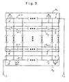
- FIG. 3 shows a further generalization of the exemplary embodiment from FIG. 2, in which an arbitrary number of actuation modules A 1 , A 2 ,... A M-1 , A M connected in parallel, each with an arbitrary number of buttons 1, 2,. ..., N-1, N is provided.
- the buttons of all actuation modules are used in parallel, which serve to trigger the same electrical function.
- An electrical assembly B d to B N is used to identify the corresponding function, which in turn is arranged parallel to these buttons and is provided to generate a characteristic electrical code.
- a current can also be meandering from the first outer terminal L 1 through the entire circuit arrangement to the second when buttons 1 to N are completely open outer connection L 2 flow.
- the two outer connections L 1 , L 2 form the ends of the meandering current path.
Landscapes
- Keying Circuit Devices (AREA)
- Electronic Switches (AREA)
- Push-Button Switches (AREA)
- Measuring Fluid Pressure (AREA)
Description
- Fig. 1 -
- eine Schaltungsanordnung mit zwei Betätigungsmodulen, die jeweils zwei Betätigungselemente zum Auslösen zweier unterschiedlicher elektrischer Funktionen aufweisen;
- Fig. 2 -
- eine Schaltungsanordnung mit zwei Betätigungsmodulen, die jeweils N Betätigungselemente zum Auslösen N unterschiedlicher elektrischer Funktionen aufweisen;
- Fig. 3 -
- eine Schaltungsanordnung mit M Betätigungsmodulen, die jeweils N Betätigungselemente zum Auslösen N unterschiedlicher elektrischer Funktionen aufweisen.
Claims (15)
- Anordnung zur Betätigung elektrischer Funktionselemente mit mindestens zwei räumlich voneinander getrennten Betätigungsmodulen, bei derwobei parallel zu den zum Auslösen derselben elektrischen Funktion vorgesehenen Betätigungselementen (1 bis N) jeweils eine elektrische Baugruppe (B1 - BN) angeordnet ist, mit der ein für die auszulösende elektrische Funktion charakteristischer elektrischer Code erzeugbar ist,a) definierte elektrische Funktionen jeweils wahlweise von dem einen oder dem anderen Betätigungsmodul (A1 - AM) her auslösbar sind,b) jedes der Betätigungsmodule (A1 - AM) mindestens zwei elektrische Betätigungselemente (1 - N) zum Auslösen unterschiedlicher elektrischer Funktionen aufweist undc) die zum Auslösen derselben elektrischen Funktion vorgesehenen Betätigungselemente (1 - N) unterschiedlicher Betätigungsmodule (A1 - AM) parallel zueinander geschaltet sind,
dadurch gekennzeichnet, daß die elektrischen Betätigungselemente (1 - N) innerhalb eines Betätigungsmoduls (A1 - AM) jeweils hintereinander geschaltet sind. - Anordnung nach Anspruch 1, dadurch gekennzeichnet, daß sämtliche Betätigungsmodule (A1 - AM) mit ihren Betätigungselementen (1 - N) in einen einheitlichen, zwei äußere elektrische Anschlüsse (L1, L2) aufweisenden Stromkreis integriert sind.
- Anordnung nach Anspruch 1 oder 2, dadurch gekennzeichnet, daß die einen charakteristischen Code für die jeweilige elektrische Funktion erzeugenden elektrischen Baugruppen (B1 - BN) derart auf die Betätigungsmodu-le (A1 - AM) verteilt sind, daß ein elektrischer Strom im Fall vollständig geöffneter elektrischer Betätigungselemente (1 - N) mäanderförmig durch die Anordnung fließt, wobei der Strom durch sämtliche elektrische Baugruppen (B1 - BN) fließt und jeder Schenkel der mäanderförmigen Strombahn (S) durch sämtliche Betätigungsmodule (A1 - AM) verläuft.
- Anordnung nach Anspruch 1 und 3, dadurch gekennzeichnet, daß die einen charakteristischen elektrischen Code erzeugenden elektrischen Baugruppen (B1 - BN) jeweils abwechselnd einem der beiden Betätigungsmodule (A1, A2; A1, AM) zugeordnet sind, die einen äußeren Rand der Parallelschaltung bilden.
- Anordnung nach einem der Ansprüche 2 bis 4, dadurch gekennzeichnet, daß die beiden äußeren elektrischen Anschlüsse (L11, L2) die Endpunkte der mäanderförmigen Strombahn (S) bilden.
- Anordnung nach Anspruch 5, dadurch gekennzeichnet, daß die beiden äußeren elektrischen Anschlüsse (L1, L2) mit je einem Betätigungselement (1 2; 1, N) verbunden sind, das einen maximalen Abstand von der zugehörigen, parallel geschalteten elektrischen Baugruppe (B1, B2; B1, BN) aufweist.
- Anordnung nach einem der vorhergehenden Ansprüche, dadurch gekennzeichnet, daß die elektrischen Betätigungselemente (1 - N) durch Taster gebildet werden.
- Anordnung nach einem der Ansprüche 1 bis 6, dadurch gekennzeichnet, daß die elektrischen Betätigungselemente durch Schalter gebildet werden.
- Anordnung nach einem der vorhergehenden Ansprüche, dadurch gekennzeichnet, daß die elektrische Baugruppe (B1 - BN) durch mindestens ein passives elektrisches Bauelement mit einem charakteristischen elektrischen Wert gebildet wird.
- Anordnung nach Anspruch 9, dadurch gekennzeichnet, daß es sich bei der elektrischen Baugruppe um einen Widerstand, eine Induktivität, einen Kondensator, eine Diodenschaltung oder eine Kombination solcher Bauelemente handelt.
- Anordnung nach einem der vorhergehenden Ansprüche, dadurch gekennzeichnet, daß die elektrische Baugruppe (B1 - BN) durch eine aktive elektrische Schaltung gebildet wird.
- Anordnung nach Anspruch 11, dadurch gekennzeichnet, daß die elektrische Schaltung zur Erzeugung einer charakteristischen Pulsfolge und/oder einer charakteristischen Frequenz ausgebildet ist.
- Anordnung nach einem der vorhergehenden Ansprüche, gekennzeichnet durch eine Auswerteeinheit zur Auswertung der beim Betätigen der Betätigungselemente (1 - N) ausgelösten elektrischen Signale.
- Anordnung nach einem der vorhergehenden Ansprüche, dadurch gekennzeichnet, daß die Anordnung zum Auslösen elektrischer Funktionselemente eines Kraftfahrzeugs dient.
- Anordnung nach Anspruch 14, dadurch gekennzeichnet, daß die Anordnung zumindest teilweise in ein Lenkrad integriert ist.
Applications Claiming Priority (3)
| Application Number | Priority Date | Filing Date | Title |
|---|---|---|---|
| DE1999134077 DE19934077C2 (de) | 1999-07-15 | 1999-07-15 | Anordnung zur Betätigung elektrischer Funktionselemente |
| DE19934077 | 1999-07-15 | ||
| PCT/DE2000/002389 WO2001005628A1 (de) | 1999-07-15 | 2000-07-17 | Anordnung zur betätigung elektrischer funktionselemente |
Publications (2)
| Publication Number | Publication Date |
|---|---|
| EP1196311A1 EP1196311A1 (de) | 2002-04-17 |
| EP1196311B1 true EP1196311B1 (de) | 2003-06-04 |
Family
ID=7915465
Family Applications (1)
| Application Number | Title | Priority Date | Filing Date |
|---|---|---|---|
| EP00954358A Expired - Lifetime EP1196311B1 (de) | 1999-07-15 | 2000-07-17 | Anordnung zur betätigung elektrischer funktionselemente |
Country Status (6)
| Country | Link |
|---|---|
| US (1) | US6522026B2 (de) |
| EP (1) | EP1196311B1 (de) |
| JP (1) | JP3650604B2 (de) |
| BR (1) | BR0010822A (de) |
| DE (2) | DE19934077C2 (de) |
| WO (1) | WO2001005628A1 (de) |
Families Citing this family (1)
| Publication number | Priority date | Publication date | Assignee | Title |
|---|---|---|---|---|
| DE10360422A1 (de) * | 2003-12-19 | 2005-07-21 | Brose Schließsysteme GmbH & Co.KG | Kraftfahrzeug |
Family Cites Families (7)
| Publication number | Priority date | Publication date | Assignee | Title |
|---|---|---|---|---|
| US3629608A (en) * | 1969-12-10 | 1971-12-21 | Joseph W Trindle | Remote control circuits |
| FR2184149A5 (de) | 1972-05-08 | 1973-12-21 | Gaz De France | |
| JPS5545363Y2 (de) * | 1976-06-28 | 1980-10-24 | ||
| IT1195198B (it) * | 1986-10-14 | 1988-10-12 | Roltra Spa | Sistema di comando e azionamento de gli alzacristalli elettrici in un veicolo |
| DE4240403C1 (de) * | 1992-12-02 | 1994-03-31 | Vdo Schindling | Ansteuerung von Stellgliedern in Kraftfahrzeugtüren |
| DE4326663A1 (de) | 1993-08-09 | 1995-02-16 | Rost Manfred Dr Rer Nat Habil | Anordnung zur Kühlung elektronischer Bauelemente |
| DE4328663C1 (de) * | 1993-08-26 | 1994-06-09 | Grundig Emv | Einrichtung zur Abfrage von Bedienelementen |
-
1999
- 1999-07-15 DE DE1999134077 patent/DE19934077C2/de not_active Expired - Fee Related
-
2000
- 2000-07-17 DE DE50002466T patent/DE50002466D1/de not_active Expired - Fee Related
- 2000-07-17 JP JP2001510690A patent/JP3650604B2/ja not_active Expired - Fee Related
- 2000-07-17 BR BR0010822A patent/BR0010822A/pt not_active IP Right Cessation
- 2000-07-17 WO PCT/DE2000/002389 patent/WO2001005628A1/de not_active Ceased
- 2000-07-17 EP EP00954358A patent/EP1196311B1/de not_active Expired - Lifetime
-
2002
- 2002-01-15 US US10/045,656 patent/US6522026B2/en not_active Expired - Fee Related
Also Published As
| Publication number | Publication date |
|---|---|
| DE19934077C2 (de) | 2001-12-20 |
| DE50002466D1 (de) | 2003-07-10 |
| US20020109405A1 (en) | 2002-08-15 |
| BR0010822A (pt) | 2002-03-05 |
| EP1196311A1 (de) | 2002-04-17 |
| JP3650604B2 (ja) | 2005-05-25 |
| JP2003504271A (ja) | 2003-02-04 |
| DE19934077A1 (de) | 2001-08-02 |
| WO2001005628A1 (de) | 2001-01-25 |
| US6522026B2 (en) | 2003-02-18 |
Similar Documents
| Publication | Publication Date | Title |
|---|---|---|
| EP0546455B1 (de) | Elektronische Steuereinrichtung zum Schalten mehrerer elektrischer Lasten | |
| DE102018103047A1 (de) | Türgriffanordnung für ein Kraftfahrzeug mit kapazitivem Sensor und Nahfeldkommunikation | |
| EP1544388A1 (de) | Kraftfahrzeug | |
| EP2656365B1 (de) | Ansteuerschaltung für ein elektromagnetisches relais | |
| EP1873916A2 (de) | Sichere Ausgangschaltung mit einem einkanaligen Perpherieanschluss für den Ausgang eines Bus-Teilnehmers | |
| DE19955070A1 (de) | Schalteranordnung für ein Kraftfahrzeug | |
| EP1603282A1 (de) | Verfahren zur Adressierung der Teilnehmer eines Bussystems | |
| EP0817226A2 (de) | Wipptaster | |
| DE10061025B4 (de) | Mehrstellungs-Schalter-Anordnung in Kraftfahrzeugen | |
| DE19934077C2 (de) | Anordnung zur Betätigung elektrischer Funktionselemente | |
| EP1444782B1 (de) | Vorrichtung zur ansteuerung einer elektrischen last und steuergerät | |
| EP0809266A2 (de) | Niederspannungsschaltgerät | |
| EP0528317B1 (de) | Steuervorrichtung in Kraftfahrzeugen | |
| DE102009006311B4 (de) | Drahtloser Fernsteuersender kleiner Leistung | |
| EP1353344B1 (de) | Schaltvorrichtung zur Signalisierung einer binaeren information | |
| EP0270622A1 (de) | Elektronische steuerschaltung, insbesondere für einen drucker. | |
| DE102020126073A1 (de) | Halbleiterrelaismodul und halbleiterrelaiskreis | |
| DE19733019C2 (de) | Elektrische Schaltungsanordnung | |
| EP1279561A2 (de) | Kraftfahrzeug-Schaltmodul | |
| DE102022122527A1 (de) | Relaisvorrichtung und Sicherheitsschaltgerät mit mindestens einer Relaisvorrichtung | |
| DE102024201251A1 (de) | Elektrische Komponente und Verfahren zur Masseanbindung einer elektrischen Komponente | |
| DE102005050239B4 (de) | Schaltungsanordnung zur redundanten Signalisierung des Schaltzustandes mindestens eines Schaltmittels | |
| EP2337054B1 (de) | Sicherheitsrelaisschaltung | |
| WO2023117777A1 (de) | Steuereinrichtung zum steuern wenigstens eines elektrisch steuerbaren steuerelements, steuerschaltung hiermit, fahrzeugsteuerung, kraftfahrzeug sowie verfahren zum herstellen einer steuerschaltung | |
| DE102018118236A1 (de) | Kontrollsystem für ein Kraftfahrzeug und Verfahren zur Fehlerdiagnose bei einem Kontrollsystem |
Legal Events
| Date | Code | Title | Description |
|---|---|---|---|
| PUAI | Public reference made under article 153(3) epc to a published international application that has entered the european phase |
Free format text: ORIGINAL CODE: 0009012 |
|
| 17P | Request for examination filed |
Effective date: 20010803 |
|
| AK | Designated contracting states |
Kind code of ref document: A1 Designated state(s): AT BE CH CY DE DK ES FI FR GB GR IE IT LI LU MC NL PT SE |
|
| GRAH | Despatch of communication of intention to grant a patent |
Free format text: ORIGINAL CODE: EPIDOS IGRA |
|
| GRAH | Despatch of communication of intention to grant a patent |
Free format text: ORIGINAL CODE: EPIDOS IGRA |
|
| GRAA | (expected) grant |
Free format text: ORIGINAL CODE: 0009210 |
|
| AK | Designated contracting states |
Designated state(s): DE FR GB SE |
|
| REG | Reference to a national code |
Ref country code: GB Ref legal event code: FG4D Free format text: NOT ENGLISH |
|
| REG | Reference to a national code |
Ref country code: IE Ref legal event code: FG4D Free format text: GERMAN |
|
| REF | Corresponds to: |
Ref document number: 50002466 Country of ref document: DE Date of ref document: 20030710 Kind code of ref document: P |
|
| REG | Reference to a national code |
Ref country code: SE Ref legal event code: TRGR |
|
| GBT | Gb: translation of ep patent filed (gb section 77(6)(a)/1977) | ||
| REG | Reference to a national code |
Ref country code: IE Ref legal event code: FD4D |
|
| ET | Fr: translation filed | ||
| PLBE | No opposition filed within time limit |
Free format text: ORIGINAL CODE: 0009261 |
|
| STAA | Information on the status of an ep patent application or granted ep patent |
Free format text: STATUS: NO OPPOSITION FILED WITHIN TIME LIMIT |
|
| 26N | No opposition filed |
Effective date: 20040305 |
|
| PGFP | Annual fee paid to national office [announced via postgrant information from national office to epo] |
Ref country code: SE Payment date: 20060705 Year of fee payment: 7 |
|
| PGFP | Annual fee paid to national office [announced via postgrant information from national office to epo] |
Ref country code: GB Payment date: 20060712 Year of fee payment: 7 |
|
| PGFP | Annual fee paid to national office [announced via postgrant information from national office to epo] |
Ref country code: DE Payment date: 20060713 Year of fee payment: 7 |
|
| PGFP | Annual fee paid to national office [announced via postgrant information from national office to epo] |
Ref country code: FR Payment date: 20060719 Year of fee payment: 7 |
|
| EUG | Se: european patent has lapsed | ||
| GBPC | Gb: european patent ceased through non-payment of renewal fee |
Effective date: 20070717 |
|
| PG25 | Lapsed in a contracting state [announced via postgrant information from national office to epo] |
Ref country code: DE Free format text: LAPSE BECAUSE OF NON-PAYMENT OF DUE FEES Effective date: 20080201 Ref country code: SE Free format text: LAPSE BECAUSE OF NON-PAYMENT OF DUE FEES Effective date: 20070718 |
|
| PG25 | Lapsed in a contracting state [announced via postgrant information from national office to epo] |
Ref country code: GB Free format text: LAPSE BECAUSE OF NON-PAYMENT OF DUE FEES Effective date: 20070717 |
|
| REG | Reference to a national code |
Ref country code: FR Ref legal event code: ST Effective date: 20080331 |
|
| PG25 | Lapsed in a contracting state [announced via postgrant information from national office to epo] |
Ref country code: FR Free format text: LAPSE BECAUSE OF NON-PAYMENT OF DUE FEES Effective date: 20070731 |