EP1195498B1 - Schildvortrieb-Tunnelbohrmaschine - Google Patents
Schildvortrieb-Tunnelbohrmaschine Download PDFInfo
- Publication number
- EP1195498B1 EP1195498B1 EP00121737A EP00121737A EP1195498B1 EP 1195498 B1 EP1195498 B1 EP 1195498B1 EP 00121737 A EP00121737 A EP 00121737A EP 00121737 A EP00121737 A EP 00121737A EP 1195498 B1 EP1195498 B1 EP 1195498B1
- Authority
- EP
- European Patent Office
- Prior art keywords
- shield tunnelling
- tunnelling apparatus
- rollers
- shield
- discharge
- Prior art date
- Legal status (The legal status is an assumption and is not a legal conclusion. Google has not performed a legal analysis and makes no representation as to the accuracy of the status listed.)
- Expired - Lifetime
Links
Images

Classifications
-
- E—FIXED CONSTRUCTIONS
- E21—EARTH OR ROCK DRILLING; MINING
- E21D—SHAFTS; TUNNELS; GALLERIES; LARGE UNDERGROUND CHAMBERS
- E21D9/00—Tunnels or galleries, with or without linings; Methods or apparatus for making thereof; Layout of tunnels or galleries
- E21D9/12—Devices for removing or hauling away excavated material or spoil; Working or loading platforms
- E21D9/124—Helical conveying means therefor
-
- E—FIXED CONSTRUCTIONS
- E21—EARTH OR ROCK DRILLING; MINING
- E21D—SHAFTS; TUNNELS; GALLERIES; LARGE UNDERGROUND CHAMBERS
- E21D9/00—Tunnels or galleries, with or without linings; Methods or apparatus for making thereof; Layout of tunnels or galleries
- E21D9/06—Making by using a driving shield, i.e. advanced by pushing means bearing against the already placed lining
- E21D9/0642—Making by using a driving shield, i.e. advanced by pushing means bearing against the already placed lining the shield having means for additional processing at the front end
- E21D9/0657—Making by using a driving shield, i.e. advanced by pushing means bearing against the already placed lining the shield having means for additional processing at the front end structurally associated with rock crushers
Definitions
- the invention is based on the object, a Schildvortriebs adopted specify the type mentioned, with the without changing the operating mode continuously both material with a high proportion of coarse fraction as well as heavily silty Material safe from additives Removal space is removable.
- the inventive design of the discharge device as a throttle unit with at least one pair each other Opposite rolling results from the composition to be removed from the discharge device Materials basically largely independent conveying effect.
- the opposing rollers promote due to the suction and transport effect continuously both flowable, for example highly sulphurous material as well as a high proportion of Coarse fraction material without a change in the mode or the addition of additives must be made.
- the throttle unit according to the invention also causes at relatively low-viscosity degraded material due the increased flow resistance an effective pressure reduction, to reduce the risk of a collapse of the working face.
- the throttle unit in the region of a conveying direction of the discharge device connected end - formed compression space, in the extracted material is compressed.
- each Roller has a number of radially projecting protrusions, with which components of a coarse fraction comminuted are.
- the projections are advantageously comb-like arranged in rows.
- the projections end a bevel and / or that the projections sawtooth with a front in the direction of rotation steep slope and with one of steep flank opposite flattened flank formed are.
- the discharge device comprising a discharge unit connected to the throttle unit. This will make an efficient breakdown of one may still be achieved residual pressure.
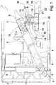
- Fig. 1 shows a partially sectioned side view of an embodiment a shield propulsion device according to the invention 1 with a local in operation arranged on the breast side Cutting wheel 2, the dismantling in front of a working space 3 is arranged.
- the shield advancing device 1 has a removal device 4 on, one with its front end in the Removal space 3 protruding rotatable screw conveyor 5 and a screw conveyor 5 the back of the working space 3 surrounding Sheath 6 has.
- the screw conveyor 5 ends to form a compression space 7 in the cladding tube 6 at a distance from that of the excavation space 3 technological end of the cladding tube 6.
- Bei Proper arrangement of Schildvortriebs Republic 1 is in the region of the compression chamber 7 via a curved Pipe socket 8 hanging down a throttling unit 9 attached to a discharge device 10.
- the throttle unit 9 is a compression chamber side closure slide 11 separated from the compression chamber 7.
- the Throttle unit 9 has a roller housing 12, in which at the illustrated embodiment by a first Discharge roller 13 and a second discharge roller 14 formed Pair of rollers is arranged.
- the first discharge roller 13 and the second discharge roller 14 are mutually displaceable, so that they are in different positions with different ones Distances are positioned from each other.
- the discharge rollers 13, 14 are rotatable in opposite directions, wherein the respective direction of rotation of the discharge rollers 13, 14 in their facing each other from the compression space 7th the discharge device 4 points away.
- Speed and the distance of the discharge rollers 13, 14 is the Flow rate and the reduction of the am in the conveying direction of Abillervoruze 4 rear end of the auger. 5 ruling residual pressure adjustable.
- Each of the discharge rollers 13, 14 has a number of comb-like arranged in rows and in that shown in Fig. 1 Position of the discharge rollers 13, 14 circumferentially interlocking Walzenzähnen 15 as radially protruding projections on, in a manner explained in more detail below are arranged to be in the introduced into the throttle unit 9 To crush material containing coarse fraction.
- the discharge device 10 has a Discharge unit 16, with the throttle unit 9 via an on the arranged from the compression chamber 7 pioneering outlet Abvant seasonen closure slide 17 is in communication.
- the discharge unit 16 is a double piston pump with a executed first piston 18 and a second piston 19, wherein the pistons 18, 19 operate in opposite directions to from the Throttling unit 9 introduced into a chambered AbGermanraum 20 Material after passing through a Abrioschieber 21st in a curved first discharge pipe 22 and in a curved second discharge pipe 23 to move.
- the Curvature in the discharge tubes 22, 23 results in a relatively high flow resistance, with the one under circumstances at the outlet of the throttle unit 9 still prevailing Residual pressure is degradable.
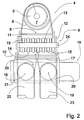
- Fig. 2 shows in a partially sectioned end view of the arrangement the throttling unit 9 according to FIG. 2 between the discharge device 4 and the discharge unit 16. From Fig. 2 it can be seen that the first discharge roller 13 and the corresponding in the Representation of FIG. 2 partially hidden second discharge roller 14 each have a motor-driven roller shaft 24 features, at which the comb-like arranged in rows and in the position of FIG. 1 circumferentially interlocking Walzenzähnen 15 are attached. Furthermore, Fig. 2 can be seen, that the pistons 18, 19 each in an associated Chamber of the Abscienceraumes 20 work.
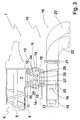
- FIG. 3 shows an enlarged in relation to the scale of FIG. 1
- Side view of the embodiment of FIG. 1 with the discharge rollers 13, 14 in a further spaced Position are arranged, in which the circumferential lines of the roller teeth 15 a with respect to the diameter of the discharge rollers 13, 14 have a relatively small distance. In this position is relatively, for example, against crushing resistant coarse fraction up to a certain the roller teeth 15 not overstressing grain size comminuted.
- FIG. 4 shows a plan view of the throttle unit 9 according to FIG. 3.
- Fig. 4 it can be seen that the roller teeth 15 of the discharge rollers 13, 14 circumferentially at a relatively small distance are arranged one another, so that in the throttle unit. 9 entering coarse fraction is crushed to a particle size, the approximately corresponds to the distance of the roller teeth 15.
Landscapes
- Engineering & Computer Science (AREA)
- Mining & Mineral Resources (AREA)
- Geology (AREA)
- Life Sciences & Earth Sciences (AREA)
- General Life Sciences & Earth Sciences (AREA)
- Geochemistry & Mineralogy (AREA)
- Environmental & Geological Engineering (AREA)
- Architecture (AREA)
- Structural Engineering (AREA)
- Excavating Of Shafts Or Tunnels (AREA)
- Earth Drilling (AREA)
- Control Of Motors That Do Not Use Commutators (AREA)
- Separation By Low-Temperature Treatments (AREA)
- Paper (AREA)
Description
- Fig. 1
- in einer teilgeschnittenen Seitenansicht ein Ausführungsbeispiel einer erfindungsgemäßen Schildvortriebseinrichtung mit einer ein Paar von in einer ersten Stellung ineinandergreifend angeordnete Walzen aufweisenden Drosseleinheit, die endseitig an eine Abfördervorrichtung angeschlossen ist und mit einer Abführeinheit in Verbindung steht,
- Fig. 2
- in einer teilgeschnittenen Stirnansicht die Anordnung der Drosseleinheit gemäß Fig. 2 zwischen der Abfördervorrichtung und der Abführeinheit,
- Fig. 3
- in einer gegenüber dem Maßstab der Fig. 1 vergrößerten Seitenansicht das Ausführungsbeispiel gemäß Fig. 1 mit in einer weiteren Stellung mit ihren Umfangslinien beabstandet angeordneten Walzen und
- Fig. 4
- eine Draufsicht auf die Drosseleinheit in der Stellung der Walzen gemäß Fig. 3.
Claims (10)
- Schildvortriebseinrichtung mit einer eine Förderschnecke (5) aufweisenden Abfördervorrichtung (4) zum Abfördern von Material aus einem Abbauraum (3) und mit einer an die Abfördervorrichtung (4) angeschlossenen Ausschleusvorrichtung (10) zum Entfernen des Materials aus der Abfördervorrichtung (4), dadurch gekennzeichnet, dass die Ausschleusvorrichtung (10) eine Drosseleinheit (9) mit wenigstens einem Paar einander gegenüberliegender Walzen (13, 14) aufweist, die jeweils paarweise gegenläufig drehbar sind, wobei die jeweilige Drehrichtung der Walzen (13, 14) in ihren aufeinander zu weisenden Bereichen von der Abfördervorrichtung wegweist.
- Schildvortriebseinrichtung nach Anspruch 1, dadurch gekennzeichnet, dass die Drosseleinheit (9) im Bereich eines in Förderrichtung der Abfördervorrichtung (4) endseitig ausgebildeten Verdichtungsraumes (7) angeschlossen ist.
- Schildvortriebeinrichtung nach Anspruch 1 oder Anspruch 2, dadurch gekennzeichnet, dass jede Walze (13, 14) eine Anzahl von radial vorstehenden Vorsprüngen (15) aufweist.
- Schildvortriebseinrichtung nach Anspruch 3, dadurch gekennzeichnet, dass die Walzen (13, 14) gegeneinander verschiebbar sind.
- Schildvortriebseinrichtung nach Anspruch 3 oder Anspruch 4, dadurch gekennzeichnet, dass die Vorsprünge (15) kammartig in Reihen angeordnet sind.
- Schildvortriebseinrichtung nach einem der Ansprüche 3 bis 5, dadurch gekennzeichnet, dass die Vorsprünge (15) endseitig einen Anschliff (25) aufweisen.
- Schildvortriebseinrichtung nach einem der Ansprüche 3 bis 6 dadurch gekennzeichnet, dass die Vorsprünge (15) sägezahnartig mit einer in Drehrichtung vorderen steilen Flanke (26) und mit einer der steilen Flanke (26) gegenüberliegenden abgeflachten Flanke (27) ausgebildet sind.
- Schildvortriebseinrichtung nach einem der Ansprüche 1 bis 7, dadurch gekennzeichnet, dass die Ausschleusvorrichtung (10) eine mit der Drosseleinheit (9) verbundene Abführeinheit (16) aufweist.
- Schildvortriebseinrichtung nach Anspruch 8, dadurch gekennzeichnet, dass die Abführeinheit (16) als Doppelkolbenpumpe mit wenigstens zwei paarweise gegensinnig arbeitenden Kolben (18, 19) ausgeführt ist.
- Schildvortriebseinrichtung nach Anspruch 9, dadurch gekennzeichnet, dass die Abführeinheit (16) in Verlängerung jeweils eines Kolbens (18, 19) angeordnete gekrümmte Abführrohre (22, 23) aufweist.
Priority Applications (6)
| Application Number | Priority Date | Filing Date | Title |
|---|---|---|---|
| PT00121737T PT1195498E (pt) | 2000-10-05 | 2000-10-05 | Maquina tuneladora de escudo |
| EP00121737A EP1195498B1 (de) | 2000-10-05 | 2000-10-05 | Schildvortrieb-Tunnelbohrmaschine |
| DE50011858T DE50011858D1 (de) | 2000-10-05 | 2000-10-05 | Schildvortrieb-Tunnelbohrmaschine |
| DK00121737T DK1195498T3 (da) | 2000-10-05 | 2000-10-05 | Skjoldfremdriftsindretning |
| ES00121737T ES2253169T3 (es) | 2000-10-05 | 2000-10-05 | Maquina tuneladora de avance por escudo. |
| AT00121737T ATE313005T1 (de) | 2000-10-05 | 2000-10-05 | Schildvortrieb-tunnelbohrmaschine |
Applications Claiming Priority (1)
| Application Number | Priority Date | Filing Date | Title |
|---|---|---|---|
| EP00121737A EP1195498B1 (de) | 2000-10-05 | 2000-10-05 | Schildvortrieb-Tunnelbohrmaschine |
Publications (2)
| Publication Number | Publication Date |
|---|---|
| EP1195498A1 EP1195498A1 (de) | 2002-04-10 |
| EP1195498B1 true EP1195498B1 (de) | 2005-12-14 |
Family
ID=8170017
Family Applications (1)
| Application Number | Title | Priority Date | Filing Date |
|---|---|---|---|
| EP00121737A Expired - Lifetime EP1195498B1 (de) | 2000-10-05 | 2000-10-05 | Schildvortrieb-Tunnelbohrmaschine |
Country Status (6)
| Country | Link |
|---|---|
| EP (1) | EP1195498B1 (de) |
| AT (1) | ATE313005T1 (de) |
| DE (1) | DE50011858D1 (de) |
| DK (1) | DK1195498T3 (de) |
| ES (1) | ES2253169T3 (de) |
| PT (1) | PT1195498E (de) |
Families Citing this family (3)
| Publication number | Priority date | Publication date | Assignee | Title |
|---|---|---|---|---|
| CN110005424B (zh) * | 2019-04-22 | 2024-11-22 | 中建三局基础设施建设投资有限公司 | 一种用于减弱盾构螺旋机喷涌的装置及其使用方法 |
| CN111577298B (zh) * | 2020-05-28 | 2025-01-07 | 中铁十一局集团城市轨道工程有限公司 | 防涌水涌砂的安全出土盾构机螺旋输送机 |
| CN111636818A (zh) * | 2020-06-09 | 2020-09-08 | 温州市晨绕机械科技有限公司 | 一种用于自动清淤的钻井装置 |
Family Cites Families (11)
| Publication number | Priority date | Publication date | Assignee | Title |
|---|---|---|---|---|
| US4407622A (en) * | 1981-05-18 | 1983-10-04 | Okumura Corporation | Soil transporting vehicle for transporting soils excavated by shield machine |
| DE3317166A1 (de) * | 1983-05-11 | 1984-11-15 | Alexander 5100 Aachen Malmendier | Rohrvortriebsvorrichtung mit abschottung |
| DE8511967U1 (de) * | 1985-04-23 | 1986-07-31 | Strabag Bau-AG, 5000 Köln | Tunnelvortriebsmaschine |
| DE3622267A1 (de) * | 1986-07-02 | 1988-01-07 | Hochtief Ag Hoch Tiefbauten | Foerdereinrichtung fuer eine vortriebsmaschine fuer tunnel und strecken |
| US4818026A (en) * | 1987-12-29 | 1989-04-04 | Kabushiki Kaisha Komatsu Seisakusho | Shield type tunneling apparatus |
| BE1004739A3 (nl) * | 1991-04-04 | 1993-01-19 | Denys Nv | Tunnelboormachine. |
| FR2679596B1 (fr) * | 1991-07-24 | 1993-11-05 | Gtm Btp | Dispositif de transfert de gravats produits a la tete d'un tunnelier, et tunnelier comportant un tel dispositif. |
| FR2679959B1 (fr) * | 1991-08-02 | 1993-11-19 | Gtm Btp | Procede pour regler la pression dans la partie amont d'un tunnelier a pression de terre, et dispositif pour la mise en óoeuvre de ce procede. |
| JPH05106393A (ja) * | 1991-10-15 | 1993-04-27 | Kawasaki Heavy Ind Ltd | シールド掘進機 |
| JP3251468B2 (ja) * | 1995-06-08 | 2002-01-28 | 株式会社奥村組 | 礫破砕装置 |
| DE19534814A1 (de) * | 1995-09-20 | 1997-03-27 | Wirth Co Kg Masch Bohr | Tunnelbohrmaschine |
-
2000
- 2000-10-05 DK DK00121737T patent/DK1195498T3/da active
- 2000-10-05 DE DE50011858T patent/DE50011858D1/de not_active Expired - Lifetime
- 2000-10-05 PT PT00121737T patent/PT1195498E/pt unknown
- 2000-10-05 EP EP00121737A patent/EP1195498B1/de not_active Expired - Lifetime
- 2000-10-05 ES ES00121737T patent/ES2253169T3/es not_active Expired - Lifetime
- 2000-10-05 AT AT00121737T patent/ATE313005T1/de active
Also Published As
| Publication number | Publication date |
|---|---|
| PT1195498E (pt) | 2006-05-31 |
| ES2253169T3 (es) | 2006-06-01 |
| ATE313005T1 (de) | 2005-12-15 |
| DE50011858D1 (de) | 2006-01-19 |
| DK1195498T3 (da) | 2006-05-08 |
| EP1195498A1 (de) | 2002-04-10 |
Similar Documents
| Publication | Publication Date | Title |
|---|---|---|
| DE2509081C2 (de) | Dickstoffpumpe | |
| DE3609111C2 (de) | ||
| EP2475889B1 (de) | Drehkolbenpumpe | |
| EP2852474B1 (de) | Schlagvorrichtung | |
| DE102013014837B4 (de) | Verfahren und Vorrichtung zum Entfernen von Bodenmaterial vor der Vorderwand einer Schildvortriebsmaschine (SVM) | |
| EP1584820B1 (de) | Schraubenzentrifugalradpumpe | |
| EP0098340B1 (de) | Schneckenpumpe mit an beiden Enden gelagerter Schnecke | |
| DE10150006A1 (de) | Ringextruder mit teilgekappten Förderelementen im Einzugsbereich | |
| DE102013010769B4 (de) | Verfahren und Vorrichtung zum Entfernen von Bodenmaterial vor der Vorderwand einer Schildvortriebsmaschine (SVM) | |
| EP1195498A1 (de) | Schildvortrieb-Tunnelbohrmaschine | |
| DE102011000732B3 (de) | Drehkolbenpumpe | |
| DE102014113602A1 (de) | Vorrichtung zur Förderung des Abbaubodens in einer Schildvortriebsmaschine (SVM) | |
| DE4240297C2 (de) | Schildvortriebsmaschine mit einer Dickstoffkolbenpumpenfördereinrichtung | |
| DE2842131C3 (de) | Schrämwalze | |
| CH683861A5 (de) | Tunnelvortriebsmaschine. | |
| DE3144613A1 (de) | Siebfoerderrost mit rotierenden rostwalzen | |
| DE3537780A1 (de) | Vorrichtung zum herstellen von stollen oder tunnel durch schildvortrieb | |
| DE3823863A1 (de) | Verfahren fuer den untertagebetrieb mit hydraulischer foerderung und anlage zur durchfuehrung des verfahrens | |
| EP0136600A2 (de) | Prallmühle | |
| DE19619532C2 (de) | Verfahren zur Herstellung einer begehbarer Tunnelverbindung zwischen zwei benachbarten, verbohrten Schachtbohrungen und Vorrichtung zur Durchführung des Verfahrens | |
| DE8716926U1 (de) | Bohrschnecke | |
| DE3920163C1 (de) | ||
| DE3226526A1 (de) | Verfahren und vorrichtung zum foerdern und abmessen von feststoffen | |
| DE102014117326A1 (de) | Vorrichtung und Verfahren zur Förderung des Abbaubodens in einer Schildvortriebsmaschine (SVM) | |
| DE102023128576A1 (de) | Kreiselradumpe mit ausfahrbaren Schaufeln |
Legal Events
| Date | Code | Title | Description |
|---|---|---|---|
| PUAI | Public reference made under article 153(3) epc to a published international application that has entered the european phase |
Free format text: ORIGINAL CODE: 0009012 |
|
| AK | Designated contracting states |
Kind code of ref document: A1 Designated state(s): AT BE CH CY DE DK ES FI FR GB GR IE IT LI LU MC NL PT SE |
|
| AX | Request for extension of the european patent |
Free format text: AL;LT;LV;MK;RO;SI |
|
| 17P | Request for examination filed |
Effective date: 20020817 |
|
| AKX | Designation fees paid |
Free format text: AT BE CH CY DE DK ES FI FR GB GR IE IT LI LU MC NL PT SE |
|
| GRAP | Despatch of communication of intention to grant a patent |
Free format text: ORIGINAL CODE: EPIDOSNIGR1 |
|
| GRAS | Grant fee paid |
Free format text: ORIGINAL CODE: EPIDOSNIGR3 |
|
| GRAA | (expected) grant |
Free format text: ORIGINAL CODE: 0009210 |
|
| AK | Designated contracting states |
Kind code of ref document: B1 Designated state(s): AT BE CH CY DE DK ES FI FR GB GR IE IT LI LU MC NL PT SE |
|
| PG25 | Lapsed in a contracting state [announced via postgrant information from national office to epo] |
Ref country code: IT Free format text: LAPSE BECAUSE OF FAILURE TO SUBMIT A TRANSLATION OF THE DESCRIPTION OR TO PAY THE FEE WITHIN THE PRESCRIBED TIME-LIMIT;WARNING: LAPSES OF ITALIAN PATENTS WITH EFFECTIVE DATE BEFORE 2007 MAY HAVE OCCURRED AT ANY TIME BEFORE 2007. THE CORRECT EFFECTIVE DATE MAY BE DIFFERENT FROM THE ONE RECORDED. Effective date: 20051214 Ref country code: FI Free format text: LAPSE BECAUSE OF FAILURE TO SUBMIT A TRANSLATION OF THE DESCRIPTION OR TO PAY THE FEE WITHIN THE PRESCRIBED TIME-LIMIT Effective date: 20051214 |
|
| REG | Reference to a national code |
Ref country code: GB Ref legal event code: FG4D Free format text: NOT ENGLISH |
|
| REG | Reference to a national code |
Ref country code: CH Ref legal event code: EP |
|
| REG | Reference to a national code |
Ref country code: IE Ref legal event code: FG4D Free format text: LANGUAGE OF EP DOCUMENT: GERMAN |
|
| REF | Corresponds to: |
Ref document number: 50011858 Country of ref document: DE Date of ref document: 20060119 Kind code of ref document: P |
|
| REG | Reference to a national code |
Ref country code: SE Ref legal event code: TRGR |
|
| GBT | Gb: translation of ep patent filed (gb section 77(6)(a)/1977) |
Effective date: 20060228 |
|
| REG | Reference to a national code |
Ref country code: CH Ref legal event code: NV Representative=s name: ISLER & PEDRAZZINI AG |
|
| REG | Reference to a national code |
Ref country code: DK Ref legal event code: T3 |
|
| REG | Reference to a national code |
Ref country code: GR Ref legal event code: EP Ref document number: 20060400912 Country of ref document: GR |
|
| REG | Reference to a national code |
Ref country code: PT Ref legal event code: SC4A Effective date: 20060314 |
|
| REG | Reference to a national code |
Ref country code: ES Ref legal event code: FG2A Ref document number: 2253169 Country of ref document: ES Kind code of ref document: T3 |
|
| ET | Fr: translation filed | ||
| PLBE | No opposition filed within time limit |
Free format text: ORIGINAL CODE: 0009261 |
|
| STAA | Information on the status of an ep patent application or granted ep patent |
Free format text: STATUS: NO OPPOSITION FILED WITHIN TIME LIMIT |
|
| PG25 | Lapsed in a contracting state [announced via postgrant information from national office to epo] |
Ref country code: MC Free format text: LAPSE BECAUSE OF NON-PAYMENT OF DUE FEES Effective date: 20061031 |
|
| 26N | No opposition filed |
Effective date: 20060915 |
|
| REG | Reference to a national code |
Ref country code: CH Ref legal event code: PCAR Free format text: ISLER & PEDRAZZINI AG;POSTFACH 1772;8027 ZUERICH (CH) |
|
| PG25 | Lapsed in a contracting state [announced via postgrant information from national office to epo] |
Ref country code: LU Free format text: LAPSE BECAUSE OF NON-PAYMENT OF DUE FEES Effective date: 20061005 |
|
| PG25 | Lapsed in a contracting state [announced via postgrant information from national office to epo] |
Ref country code: CY Free format text: LAPSE BECAUSE OF FAILURE TO SUBMIT A TRANSLATION OF THE DESCRIPTION OR TO PAY THE FEE WITHIN THE PRESCRIBED TIME-LIMIT Effective date: 20051214 |
|
| REG | Reference to a national code |
Ref country code: FR Ref legal event code: PLFP Year of fee payment: 16 |
|
| REG | Reference to a national code |
Ref country code: FR Ref legal event code: PLFP Year of fee payment: 17 |
|
| REG | Reference to a national code |
Ref country code: FR Ref legal event code: PLFP Year of fee payment: 18 |
|
| PGFP | Annual fee paid to national office [announced via postgrant information from national office to epo] |
Ref country code: PT Payment date: 20170926 Year of fee payment: 18 |
|
| PGFP | Annual fee paid to national office [announced via postgrant information from national office to epo] |
Ref country code: DK Payment date: 20171024 Year of fee payment: 18 |
|
| PGFP | Annual fee paid to national office [announced via postgrant information from national office to epo] |
Ref country code: SE Payment date: 20171024 Year of fee payment: 18 Ref country code: AT Payment date: 20171018 Year of fee payment: 18 Ref country code: CH Payment date: 20171023 Year of fee payment: 18 Ref country code: IE Payment date: 20171020 Year of fee payment: 18 Ref country code: BE Payment date: 20171023 Year of fee payment: 18 Ref country code: GR Payment date: 20171026 Year of fee payment: 18 |
|
| REG | Reference to a national code |
Ref country code: FR Ref legal event code: PLFP Year of fee payment: 19 |
|
| PGFP | Annual fee paid to national office [announced via postgrant information from national office to epo] |
Ref country code: NL Payment date: 20181022 Year of fee payment: 19 |
|
| PGFP | Annual fee paid to national office [announced via postgrant information from national office to epo] |
Ref country code: FR Payment date: 20181023 Year of fee payment: 19 Ref country code: GB Payment date: 20181025 Year of fee payment: 19 Ref country code: IT Payment date: 20181022 Year of fee payment: 19 Ref country code: ES Payment date: 20181122 Year of fee payment: 19 |
|
| REG | Reference to a national code |
Ref country code: DK Ref legal event code: EBP Effective date: 20181031 |
|
| REG | Reference to a national code |
Ref country code: SE Ref legal event code: EUG |
|
| REG | Reference to a national code |
Ref country code: CH Ref legal event code: PL |
|
| REG | Reference to a national code |
Ref country code: AT Ref legal event code: MM01 Ref document number: 313005 Country of ref document: AT Kind code of ref document: T Effective date: 20181005 |
|
| REG | Reference to a national code |
Ref country code: BE Ref legal event code: MM Effective date: 20181031 |
|
| REG | Reference to a national code |
Ref country code: IE Ref legal event code: MM4A |
|
| PG25 | Lapsed in a contracting state [announced via postgrant information from national office to epo] |
Ref country code: SE Free format text: LAPSE BECAUSE OF NON-PAYMENT OF DUE FEES Effective date: 20181006 Ref country code: PT Free format text: LAPSE BECAUSE OF NON-PAYMENT OF DUE FEES Effective date: 20190405 |
|
| PG25 | Lapsed in a contracting state [announced via postgrant information from national office to epo] |
Ref country code: CH Free format text: LAPSE BECAUSE OF NON-PAYMENT OF DUE FEES Effective date: 20181031 Ref country code: LI Free format text: LAPSE BECAUSE OF NON-PAYMENT OF DUE FEES Effective date: 20181031 Ref country code: GR Free format text: LAPSE BECAUSE OF NON-PAYMENT OF DUE FEES Effective date: 20190506 Ref country code: BE Free format text: LAPSE BECAUSE OF NON-PAYMENT OF DUE FEES Effective date: 20181031 |
|
| PG25 | Lapsed in a contracting state [announced via postgrant information from national office to epo] |
Ref country code: DK Free format text: LAPSE BECAUSE OF NON-PAYMENT OF DUE FEES Effective date: 20181031 Ref country code: AT Free format text: LAPSE BECAUSE OF NON-PAYMENT OF DUE FEES Effective date: 20181005 Ref country code: IE Free format text: LAPSE BECAUSE OF NON-PAYMENT OF DUE FEES Effective date: 20181005 |
|
| PGFP | Annual fee paid to national office [announced via postgrant information from national office to epo] |
Ref country code: DE Payment date: 20191015 Year of fee payment: 20 |
|
| REG | Reference to a national code |
Ref country code: NL Ref legal event code: MM Effective date: 20191101 |
|
| PG25 | Lapsed in a contracting state [announced via postgrant information from national office to epo] |
Ref country code: NL Free format text: LAPSE BECAUSE OF NON-PAYMENT OF DUE FEES Effective date: 20191101 |
|
| GBPC | Gb: european patent ceased through non-payment of renewal fee |
Effective date: 20191005 |
|
| REG | Reference to a national code |
Ref country code: DE Ref legal event code: R071 Ref document number: 50011858 Country of ref document: DE |
|
| PG25 | Lapsed in a contracting state [announced via postgrant information from national office to epo] |
Ref country code: GB Free format text: LAPSE BECAUSE OF NON-PAYMENT OF DUE FEES Effective date: 20191005 Ref country code: IT Free format text: LAPSE BECAUSE OF NON-PAYMENT OF DUE FEES Effective date: 20191005 Ref country code: FR Free format text: LAPSE BECAUSE OF NON-PAYMENT OF DUE FEES Effective date: 20191031 |
|
| REG | Reference to a national code |
Ref country code: ES Ref legal event code: FD2A Effective date: 20210301 |
|
| PG25 | Lapsed in a contracting state [announced via postgrant information from national office to epo] |
Ref country code: ES Free format text: LAPSE BECAUSE OF NON-PAYMENT OF DUE FEES Effective date: 20191006 |