EP1195179A2 - Brand/Rauchschutztoranlage Bzw. Brand/Rauchschutztüranlage - Google Patents
Brand/Rauchschutztoranlage Bzw. Brand/Rauchschutztüranlage Download PDFInfo
- Publication number
- EP1195179A2 EP1195179A2 EP01123659A EP01123659A EP1195179A2 EP 1195179 A2 EP1195179 A2 EP 1195179A2 EP 01123659 A EP01123659 A EP 01123659A EP 01123659 A EP01123659 A EP 01123659A EP 1195179 A2 EP1195179 A2 EP 1195179A2
- Authority
- EP
- European Patent Office
- Prior art keywords
- fire
- protection door
- smoke protection
- smoke
- door system
- Prior art date
- Legal status (The legal status is an assumption and is not a legal conclusion. Google has not performed a legal analysis and makes no representation as to the accuracy of the status listed.)
- Granted
Links
- 239000000779 smoke Substances 0.000 title claims abstract description 122
- 238000007789 sealing Methods 0.000 claims abstract description 47
- 238000000034 method Methods 0.000 claims abstract description 17
- 230000005540 biological transmission Effects 0.000 claims abstract description 7
- 230000008878 coupling Effects 0.000 claims description 6
- 238000010168 coupling process Methods 0.000 claims description 6
- 238000005859 coupling reaction Methods 0.000 claims description 6
- 239000000565 sealant Substances 0.000 claims 1
- 238000004146 energy storage Methods 0.000 description 10
- 230000001681 protective effect Effects 0.000 description 3
- 229910000831 Steel Inorganic materials 0.000 description 2
- 238000010586 diagram Methods 0.000 description 2
- 238000005516 engineering process Methods 0.000 description 2
- 230000005764 inhibitory process Effects 0.000 description 2
- 239000000463 material Substances 0.000 description 2
- 239000010959 steel Substances 0.000 description 2
- 238000000418 atomic force spectrum Methods 0.000 description 1
- 230000006835 compression Effects 0.000 description 1
- 238000007906 compression Methods 0.000 description 1
- 230000007423 decrease Effects 0.000 description 1
- 230000003247 decreasing effect Effects 0.000 description 1
- 230000001419 dependent effect Effects 0.000 description 1
- 230000000694 effects Effects 0.000 description 1
- 239000004033 plastic Substances 0.000 description 1
- 239000007787 solid Substances 0.000 description 1
- 230000008961 swelling Effects 0.000 description 1
- 230000001960 triggered effect Effects 0.000 description 1
- 230000003313 weakening effect Effects 0.000 description 1
Images



Classifications
-
- A—HUMAN NECESSITIES
- A62—LIFE-SAVING; FIRE-FIGHTING
- A62C—FIRE-FIGHTING
- A62C2/00—Fire prevention or containment
- A62C2/06—Physical fire-barriers
- A62C2/18—Sliding dampers
Definitions
- the present invention relates to the field of Fire / smoke protection technology. It affects a fire / smoke protection gate system or Fire / smoke protection door system according to the preamble of claim 1.
- Such a fire / smoke protection door system or fire / smoke protection door system is e.g. known from US-A-4,823,509 (see FIG. 11 there).
- Known Additional devices include either mechanical energy storage such as a stretched rubber band (comparable to WO-A1-90 / 13723 or DE-A1-39 40 762), which act directly on the gate or door, or electrical energy storage (see e.g. DE-A1-38 26 718 or DE-A1-196 41 592 or die), which provide the necessary auxiliary energy for the normal electric drive Make available.
- mechanical energy storage such as a stretched rubber band (comparable to WO-A1-90 / 13723 or DE-A1-39 40 762), which act directly on the gate or door, or electrical energy storage (see e.g. DE-A1-38 26 718 or DE-A1-196 41 592 or die), which provide the necessary auxiliary energy for the normal electric drive Make available.
- the essence of the invention is the drive device for the gate or Design the door so that at the end of the closing process, when the gate or the door moves into the sealing area, applies an increased closing force.
- the increased closing force can result in the escapement caused by the seals Closing movement easily and safely overcome and a tight closing achieved become. Since only the closing force is increased, and this only at the end of the Closing process happens, can result in a corresponding increase in drive power be dispensed with if the driving speed is reduced at the same time becomes. In this way it can be used as an additional device for the supply of auxiliary energy an electrical energy storage can be used without this the seals are exposed to excessive loads.
- the increase in the closing force preferably takes place at essentially constant drive power of the drive device instead.
- the drive device is a driven includes rope-like power transmission element, which essentially in the direction of travel of the fire / smoke protection door or fire / smoke protection door runs and at a predetermined location by deflecting means in one direction across is deflected to the direction of travel when a on the power transmission element Driver is attached, and if the driver via coupling means with the The fire / smoke protection door or the fire / smoke protection door is engaged in such a way that the driver is deflected by the deflecting means if that Fire / smoke protection door or the fire / smoke protection door with the main closing edge enters the sealing area.
- the force transmission element is preferably a chain, comprising the deflection means a deflection pinion around which the chain is guided, and comprise the Coupling means one with the fire / smoke protection gate or Fire / smoke protection door connected sliding carriage that can be moved in the direction of travel, which has an elongated hole extending transversely to the direction of travel, in which the driver engages.
- the configuration with the elongated hole offers - unlike the configuration from the US-A-4,452,014 - a special additional advantage when locking of the fire / smoke protection door or the fire / smoke protection door of the driver in the Elongated hole over the parallel to the through the axis of rotation of the deflection pinion Direction of travel can be deflected.
- a "dead center lock” can be prevented in a very simple and effective manner that the closed Fire / smoke protection gate or the closed fire / smoke protection door cannot open itself (e.g. due to heat).
- the Main closing edge of the fire / smoke protection door or fire / smoke protection door an elastically deformable sealing profile is arranged, with which the Fire / smoke protection door or the fire / smoke protection door when closing in an opposite, Wall-mounted, elastically deformable counter seal profile retracts, the sealing profile preferably a substantially has triangular profile cross section and with the base side of the triangle the main closing edge of the fire / smoke protection door or the Fire / smoke protection door is present, and the counter seal profile in the profile cross section a corresponding triangular recess for receiving the sealing profile having.
- Fig. 1 is a top view from the front in a highly simplified representation a fire / smoke protection door system shown as an example for the realization the invention is suitable.
- the fire / smoke protection gate system 10 includes a Fire / smoke protection gate 11, which by means of a (in this example above the Tores attached) drive device 14 with the fire / smoke control gate 11 is coupled via a coupling device 15 in the horizontal direction (Double arrow) can be moved.
- a fire / smoke protection gate 11 In the event of a fire, it will Fire / smoke protection gate 11 from an open position (not shown) Move to the right into the shown closed position and close one Opening 13 in a wall (or wall) 12 (see also Fig. 2).
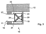
- a sealing area 16 is provided on the right vertical edge of the opening 13, into which the fire / smoke protection door 11 closes with its main closing edge 24 retracts (Fig. 3). Since the fire / smoke protection gate 11 in the example shown Moved in front of the wall 12, the sealing area 16 comprises according to FIG. 3 a placed on the wall 12, e.g. consisting of an angled steel sheet Sealing baffle 23, in which the actual seals 17, 18th and 20 are housed.
- the seal 20 is a counter seal profile which has a triangular recess in the profile cross section.
- the sealing profile 19 can for example be designed as a personal protective bar that sends a stop signal to the drive device 14 or their control releases as soon as the sealing profile 19th is pressed when an object hits the gate.
- Sealing profile 19 and counter sealing profile 20 are made of an elastically deformable Material and are against each other when the fire / smoke protection gate 11 is closed. and compressed to achieve the best possible tightness.
- An increased closing force is necessary for the compression.
- An increased closing force is also required to increase the frictional forces overcome, which are generated by two sealing lips 21 and 22.
- These sealing lips 21, 22 are on the counter sealing profile 20 on both sides of the recess molded and are in the final stages of the closing process to increase the Tightness on the two outer sides of the fire / smoke protection door 11.
- the closing process is also carried out by two sealing strips 17, 18 inhibited, between which the fire / smoke protection gate 11 in the sealing area 16 retracts and which rest on both outer sides of the gate.
- the weather strips 17, 18 are preferably made of a material that when exposed swells up from heat and thus strengthens the sealing effect, especially in extreme cases.
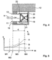
- the fire / smoke protection gate 11 travels in the direction when closed of the arrow a travel path W, which is from entering the sealing area 16 to the final closing position is a distance d, for example Is 80 mm. 3 or 4
- the required closing force K as a function of travel W is in the diagram Fig. 5 shown as a solid curve (B).
- Waypoint W1 is before Driving the gate into the sealing area 16
- the waypoint W2 marks that Entry into the sealing strips 17, 18,
- the waypoint W3 marks the entry into the back seal profile 20
- the waypoint W4 marks the end position the gate (the distance between W2 and W4 is equal to d).
- a closing force K is provided which increases with increasing travel W approximately according to the dashed curve (A) and even reached its maximum at the end point.
- a curve (A) of the closing force K by a drive device is preferred 14 generated according to FIG. 6.
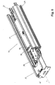
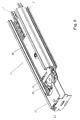
- this drive device 14 that is Fire / smoke protection gate coupled with a slide 26 (fixed or detachable)
- the by means of laterally attached sliders 31 in a profile rail 25 with a U-shaped Cross-sectional profile is mounted movable in the horizontal direction.
- the sledge 26 has at one end a crosswise to the direction of travel Slot 30 on.
- a driver 28 engages in this slot 30.
- the driver 28 is fastened on a chain 27 so as to be rotatable about a vertical central axis.
- the chain 27 runs within the profile rail 25 in the longitudinal direction and is at one end of the profile rail 25 by means of a deflection pinion 29 through 180 ° diverted.
- the chain 27 is driven by a drive sprocket (not shown), which is connected to an electric motor (possibly via a gearbox).
- the Drive is preferably uniform, so that the chain 27 with a
- the drive device 14 is now coupled with the fire / smoke protection gate 11 so that the speed component of the driver decreases in the direction of travel if that Fire / smoke protection gate 11 enters sealing area 16 and goes to zero, when the fire / smoke protection gate 11 assumes its final closing position.
- the drive power is the product of the travel speed (in the travel direction) and the closing force K corresponds to the constant drive power in such as an inversely proportional increase with decreasing travel speed Closing.
- This increased closing force is made available without that the drive power must be changed, which is the case when using a electrical auxiliary energy storage is of particular advantage. It goes without saying it goes without saying that the increase in force achieved by deflection is also achieved can be used if, instead of the chain 27, a toothed belt, a rope or the like becomes.
- the leadership of the driver 28 - be rectangular or a roll can - in the slot 30 has in addition to the described increase in force
Landscapes
- Health & Medical Sciences (AREA)
- Public Health (AREA)
- Business, Economics & Management (AREA)
- Emergency Management (AREA)
- Special Wing (AREA)
- Power-Operated Mechanisms For Wings (AREA)
- Buildings Adapted To Withstand Abnormal External Influences (AREA)
- Specific Sealing Or Ventilating Devices For Doors And Windows (AREA)
- Respiratory Apparatuses And Protective Means (AREA)
Abstract
Description
- Fig. 1
- in der Draufsicht von vorne eine stark vereinfachte Darstellung einer Brand/Rauchschutztoranlage, wie sie beispielhaft zur Verwirklichung der Erfindung geeignet ist,
- Fig. 2
- den Schnitt durch die Anlage nach Fig. 1 entlang der dortigen Ebene II-II;
- Fig. 3
- einen vergrösserten Ausschnitt des Dichtungsbereiches aus Fig. 2;
- Fig. 4
- die Verfahrrichtung und den Verfahrweg des Tores im Dichtungsbereich gemäss Fig. 3;
- Fig. 5
- in einem schematischen Diagramm die Schliesskraft (K) über den Verfahrweg (W), wie sie für die dichtungsbedingte Hemmung benötigt wird (Kurve B), wie sie von einem herkömmlichen mechanischen Hilfsenergiespeicher (Gummiseil etc.) zur Verfügung gestellt wird (Kurve C), und wie sie mit einer Kraftverstärkung gemäss der Erfindung erreicht wird (Kurve A); und
- Fig. 6a-d
- in verschiedenen Teilfiguren 6(a)-6(d) verschiedene Phasen beim Schliessvorgang mit anschliessender Totpunktverriegelung in einer Antriebsvorrichtung gemäss einem bevorzugten Ausführungsbeispiel der Erfindung.
- 10
- Brand/Rauchschutztoranlage (Brand/Rauchschutztüranlage)
- 11
- Brand/Rauchschutztor (Brand/Rauchschutztür)
- 12
- Mauer (Wand)
- 13
- Oeffnung
- 14
- Antriebsvorrichtung
- 15
- Kopplungsvorrichtung
- 16
- Dichtungsbereich
- 17,18
- Dichtungsstreifen (bei Hitze aufquellend)
- 19
- Dichtungsprofil (Tor)
- 20
- Gegendichtungsprofil
- 21,22
- Dichtlippe
- 23
- Dichtungsschikane (Stahlblech)
- 24
- Hauptschliesskante (Tor)
- 25
- Profilschiene
- 26
- Laufschlitten
- 27
- Kette
- 28
- Mitnehmer
- 29
- Umlenkritzel
- 30
- Langloch
- 31
- Gleiter (Kunststoff)
- d
- Distanz
- K
- Schliesskraft
- P
- Parallele
- W
- Verfahrweg
- W1,..,W4
- Wegpunkt
Claims (10)
- Brand/Rauchschutztoranlage bzw. Brand/Rauchschutztürananlage (10), umfassend ein(e) vorzugsweise in horizontaler Richtung verfahrbare(s) Brand/Rauchschutztor bzw. Brand/Rauchschutztür (11), welche(s) im Brandfall eine Oeffnung (13) in einer Mauer (12) verschliesst, wobei das Brand/Rauchschutztor bzw. die Brand/Rauchschutztür (11) mit seiner (ihrer) Hauptschliesskante (24) am Ende des Schliessvorgangs in einen mit Dichtmitteln (17, 18; 20) ausgerüsteten Dichtungsbereich (16) einfährt, sowie umfassend eine Antriebsvorrichtung (14), mittels derer das Brand/Rauchschutztor bzw. die Brand/Rauchschutztür (11) automatisch in die Schliessstellung verfahrbar ist, dadurch gekennzeichnet, dass die Antriebsvorrichtung (14) so ausgebildet ist, dass sie am Ende des Schliessvorgangs, wenn das Brand/Rauchschutztor bzw. die Brand/Rauchschutztür (11) in den Dichtungsbereich (16) einfährt, eine erhöhte Schliesskraft (K) aufbringt.
- Brand/Rauchschutztoranlage bzw. Brand/Rauchschutztüranlage nach Anspruch 1, dadurch gekennzeichnet, dass die erhöhte Schliesskraft (K) mit zunehmendem Verfahrweg (W) zunimmt und am Ende des Schliessvorgangs ihr Maximum erreicht.
- Brand/Rauchschutztoranlage bzw. Brand/Rauchschutztüranlage nach einem der Ansprüche 1 und 2, dadurch gekennzeichnet, dass die Erhöhung der Schliesskraft (K) bei im wesentlichen gleichbleibender Antriebsleistung der Antriebsvorrichtung (14) stattfindet.
- Brand/Rauchschutztoranlage bzw. Brand/Rauchschutztüranlage nach einem der Ansprüche 1 bis 3, dadurch gekennzeichnet, dass die Antriebsvorrichtung (14) ein angetriebenes seilartiges Kraftübertragungselement (27) umfasst, welches im wesentlichen in Verfahrrichtung des Brand/Rauchschutztores bzw. der Brand/Rauchschutztür (11) verläuft und an einem vorgegebenen Ort durch Umlenkmittel (29) in eine Richtung quer zur Verfahrrichtung umgelenkt wird, dass an dem Kraftübertragungselement (27) ein Mitnehmer (28) befestigt ist, und dass der Mitnehmer (28) über Kopplungsmittel (26, 30) mit dem Brand/Rauchschutztor bzw. der Brand/Rauchschutztür (11) derart in Eingriff steht, dass der Mitnehmer durch die Umlenkmittel (29) umgelenkt wird, wenn das Brand/Rauchschutztor bzw. die Brand/Rauchschutztür (11) mit der Hauptschliesskante (24) in den Dichtungsbereich (16) einfährt.
- Brand/Rauchschutztoranlage bzw. Brand/Rauchschutztüranlage nach Anspruch 4, dadurch gekennzeichnet, dass das Kraftübertragungselement eine Kette (27) ist, dass die Umlenkmittel ein Umlenkritzel (29) umfassen, um welches die Kette (27) geführt ist, und dass die Kopplungsmittel einen mit dem Brand/Rauchschutztor bzw. der Brand/Rauchschutztür (11) verbundenen, in Verfahrrichtung verschiebbaren Laufschlitten (26) umfassen, der ein quer zur Verfahrrichtung sich erstreckendes Langloch (30) aufweist, in welches der Mitnehmer (28) eingreift.
- Brand/Rauchschutztoranlage bzw. Brand/Rauchschutztüranlage nach Anspruch 5, dadurch gekennzeichnet, dass zur Verriegelung des Brand/Rauchschutztores bzw. der Brand/Rauchschutztür (11) der Mitnehmer (28) im Langloch (30) über die durch die Drehachse des Umlenkritzels (29) gehende Parallele (P) zur Verfahrrichtung hinaus umlenkbar ist.
- Brand/Rauchschutztoranlage bzw. Brand/Rauchschutztüranlage nach einem der Ansprüche 1 bis 6, dadurch gekennzeichnet, dass an der Hauptschliesskante (24) des Brand/Rauchschutztores bzw. der Brand/Rauchschutztür (11) ein elastisch verformbares Dichtungsprofil (19) angeordnet ist, mit welchem das Brand/Rauchschutztor bzw. der Brand/Rauchschutztür (11) beim Schliessen in ein gegenüberliegendes, an der Wand befestigtes, elastisch verformbares Gegendichtungsprofil (20) einfährt.
- Brand/Rauchschutztoranlage bzw. Brand/Rauchschutztüranlage nach Anspruch 7, dadurch gekennzeichnet, dass das Dichtungsprofil (19) einen im wesentlichen dreieckigen Profilquerschnitt aufweist und mit der Basisseite des Dreiecks an der Hauptschliesskante (24) des Brand/Rauchschutztores bzw. der Brand/Rauchschutztür (11) anliegt, und dass das Gegendichtungsprofil (20) im Profilquerschnitt eine entsprechende dreickeckförmige Ausnehmung zur Aufnahme des Dichtungsprofils (19) aufweist.
- Brand/Rauchschutztoranlage bzw. Brand/Rauchschutztüranlage nach Anspruch 8, dadurch gekennzeichnet, dass das Gegendichtungsprofil an beiden Seiten Dichtlippen (21, 22) aufweist, welche an den Aussenseiten des Brand/Rauchschutztores bzw. der Brand/Rauchschutztür (11) anliegen, wenn das Brand/Rauchschutztor bzw. die Brand/Rauchschutztür (11) in das Gegendichtungsprofil (20) einfährt.
- Brand/Rauchschutztoranlage bzw. Brand/Rauchschutztüranlage nach einem der Ansprüche 1 bis 9, dadurch gekennzeichnet, dass im Dichtungsbereich (16) bei Hitze aufquellende Dichtungsstreifen (17, 18) angeordnet sind, welche bei dem (der) in den Dichtungsbereich (16) eingefahrenen Brand/Rauchschutztor bzw. Brand/Rauchschutztür (11) an beiden Aussenseiten des Brand/Rauchschutztores bzw. der Brand/Rauchschutztür (11) anliegen.
Applications Claiming Priority (2)
| Application Number | Priority Date | Filing Date | Title |
|---|---|---|---|
| DE10049834A DE10049834C5 (de) | 2000-10-09 | 2000-10-09 | Brand/Rauchschutztoranlage bzw. Brand/Rauchschutztüranlage |
| DE10049834 | 2000-10-09 |
Publications (3)
| Publication Number | Publication Date |
|---|---|
| EP1195179A2 true EP1195179A2 (de) | 2002-04-10 |
| EP1195179A3 EP1195179A3 (de) | 2002-06-12 |
| EP1195179B1 EP1195179B1 (de) | 2009-06-24 |
Family
ID=7659075
Family Applications (1)
| Application Number | Title | Priority Date | Filing Date |
|---|---|---|---|
| EP01123659A Expired - Lifetime EP1195179B1 (de) | 2000-10-09 | 2001-10-02 | Brand/Rauchschutztoranlage Bzw. Brand/Rauchschutztüranlage |
Country Status (4)
| Country | Link |
|---|---|
| EP (1) | EP1195179B1 (de) |
| AT (1) | ATE434467T1 (de) |
| DE (2) | DE10049834C5 (de) |
| DK (1) | DK1195179T3 (de) |
Families Citing this family (1)
| Publication number | Priority date | Publication date | Assignee | Title |
|---|---|---|---|---|
| TWI750853B (zh) * | 2020-10-19 | 2021-12-21 | 寰奇機電有限公司 | 具有防火防煙捲幕主軸自動滑移機制之機箱結構 |
Citations (7)
| Publication number | Priority date | Publication date | Assignee | Title |
|---|---|---|---|---|
| US4452014A (en) | 1981-12-28 | 1984-06-05 | Markus Hermetische Deuren B.V. | Device for operating a sliding door |
| DE3709688A1 (de) | 1986-03-26 | 1987-10-01 | Yoshida Kogyo Kk | Automatische tuer mit automatischem verriegelungssystem |
| DE3826718A1 (de) | 1987-08-07 | 1989-02-16 | Yoshida Kogyo Kk | Automatisches tuerantriebssystem |
| WO1990013723A1 (de) | 1989-05-10 | 1990-11-15 | Dorma Gmbh + Co. Kg | Automatische schiebetür |
| DE3940762A1 (de) | 1989-12-09 | 1991-06-13 | Hein Gmbh Christian | Schiebetuer |
| DE19641592A1 (de) | 1996-10-09 | 1998-04-16 | Geze Gmbh & Co | Automatischer Türantrieb |
| EP0984130A2 (de) | 1998-08-06 | 2000-03-08 | agta record ag | Automatischer Türantrieb |
Family Cites Families (12)
| Publication number | Priority date | Publication date | Assignee | Title |
|---|---|---|---|---|
| DE827960C (de) * | 1950-05-12 | 1952-01-14 | Duesseldorfer Waggonfabrik A G | Mechanische Betaetigung von Dreh-, Falt- oder Schwingtueren fuer Schienen- oder Strassenfahrzeuge |
| DE1584060C3 (de) * | 1964-11-24 | 1974-03-14 | Henry Bayard Elizabeth N.J. Clark (V.St.A.) | Vorrichtung zum automatischen Schliessen einer mit einer Antriebsvorrichtung bewegbaren Feuerschutztür |
| US3461611A (en) * | 1967-10-12 | 1969-08-19 | O M Edwards Co Inc The | Safety seal for sliding doors |
| JPS5877424A (ja) * | 1981-10-28 | 1983-05-10 | Yamazaki Mazak Corp | マシニングセンタにおける工具選択制御方法 |
| KR900004810B1 (ko) * | 1984-11-27 | 1990-07-07 | 가부시기가이샤 호 와 | 자폐도어의 밀폐장치 |
| DE8900006U1 (de) * | 1988-01-25 | 1989-03-30 | Ackermann, Peter, Dr., 5100 Aachen | Vorrichtung zur vorübergehenden Abdichtung des Bodenbereiches einer Wandöffnung |
| DE8913893U1 (de) * | 1989-11-25 | 1991-03-21 | Dictator Technik Dr. Wolfram Schneider & Co Verwaltungs- und Beteiligungsgesellschaft, 86356 Neusäß | Schließvorrichtung für Türen, Tore, Fenster, Klappen o.dgl. |
| AT406853B (de) * | 1991-09-25 | 2000-10-25 | Ife Gmbh | Durchgang eines waggons des schienengebundenen personenverkehrs |
| DE4232593C1 (de) * | 1992-09-24 | 1993-12-09 | Bautzen Waggonbau Gmbh | Antrieb für Schwenktüren |
| DE19628203C2 (de) * | 1996-07-12 | 2001-11-08 | Brose Fahrzeugteile | Verfahren zur Begrenzung der Überschußkraft eines elektrisch gesteuerten, fremdkraftbetätigten Aggregats beim Anfahren seiner Schließposition, insbesondere beim Anfahren der Schließposition eines Fensterhebers eines Kraftfahrzeugs |
| DE19718237C1 (de) * | 1997-04-30 | 1999-02-04 | Theo Schroeders | Als Schiebetür oder -tor ausgebildeter Feuerschutzabschluß |
| US5782690A (en) * | 1997-06-06 | 1998-07-21 | International Business Machines Corporation | Curtain fire damper |
-
2000
- 2000-10-09 DE DE10049834A patent/DE10049834C5/de not_active Expired - Lifetime
-
2001
- 2001-10-02 DK DK01123659T patent/DK1195179T3/da active
- 2001-10-02 EP EP01123659A patent/EP1195179B1/de not_active Expired - Lifetime
- 2001-10-02 DE DE50114946T patent/DE50114946D1/de not_active Expired - Lifetime
- 2001-10-02 AT AT01123659T patent/ATE434467T1/de active
Patent Citations (7)
| Publication number | Priority date | Publication date | Assignee | Title |
|---|---|---|---|---|
| US4452014A (en) | 1981-12-28 | 1984-06-05 | Markus Hermetische Deuren B.V. | Device for operating a sliding door |
| DE3709688A1 (de) | 1986-03-26 | 1987-10-01 | Yoshida Kogyo Kk | Automatische tuer mit automatischem verriegelungssystem |
| DE3826718A1 (de) | 1987-08-07 | 1989-02-16 | Yoshida Kogyo Kk | Automatisches tuerantriebssystem |
| WO1990013723A1 (de) | 1989-05-10 | 1990-11-15 | Dorma Gmbh + Co. Kg | Automatische schiebetür |
| DE3940762A1 (de) | 1989-12-09 | 1991-06-13 | Hein Gmbh Christian | Schiebetuer |
| DE19641592A1 (de) | 1996-10-09 | 1998-04-16 | Geze Gmbh & Co | Automatischer Türantrieb |
| EP0984130A2 (de) | 1998-08-06 | 2000-03-08 | agta record ag | Automatischer Türantrieb |
Also Published As
| Publication number | Publication date |
|---|---|
| DE50114946D1 (de) | 2009-08-06 |
| DE10049834B4 (de) | 2007-06-14 |
| ATE434467T1 (de) | 2009-07-15 |
| DE10049834A1 (de) | 2002-05-02 |
| DK1195179T3 (da) | 2009-10-05 |
| EP1195179B1 (de) | 2009-06-24 |
| DE10049834C5 (de) | 2010-02-18 |
| EP1195179A3 (de) | 2002-06-12 |
Similar Documents
| Publication | Publication Date | Title |
|---|---|---|
| DE19758648C2 (de) | Crashschutzvorrichtung für Schnellaufrolltore sowie Schnellaufrolltor | |
| DE3618692C2 (de) | ||
| EP0284066B1 (de) | Schnellauftor | |
| AT4784U1 (de) | Sektionalhub- oder falttor | |
| EP1671006B1 (de) | Rolltor mit kollisionsschutz | |
| WO1999015754A1 (de) | Rolltor mit einem flexiblen torblatt | |
| EP3871831A1 (de) | Schutzabdeckung mit antriebseinrichtung zur abdeckung von beweglichen maschinenteilen | |
| EP2703591A2 (de) | Dichtvorrichtung für Schiebefenster oder Schiebetüren | |
| DE102017007097A1 (de) | Torsystem | |
| DE19949329C2 (de) | Schnellauftor | |
| EP2354415B1 (de) | Sektionaltor | |
| DE19722818A1 (de) | Torblatt-Dichtungsprofil | |
| EP1195179B1 (de) | Brand/Rauchschutztoranlage Bzw. Brand/Rauchschutztüranlage | |
| DE10160802A1 (de) | Automatische Schiebetüranlage mit Seitenprofil | |
| AT521543A2 (de) | Schutzvorrichtung für Roll- und Sektionaltore | |
| DE19715712C2 (de) | Sektionaltor | |
| EP0851083A1 (de) | Vertikalschiebefenster | |
| DE3419339A1 (de) | Fensterladen, insbesondere ein aus zwei fluegeln bestehender fensterladen | |
| DE102017101553A1 (de) | Hebeschwelle | |
| DE102018118088A1 (de) | Schutzvorrichtung für Roll- und Sektionaltore | |
| DE1933557A1 (de) | Fensterbeschlag | |
| EP1612363A2 (de) | Automatische Schiebetüranlage | |
| DE3520577A1 (de) | Elektromechanische sicherheitskontaktleiste fuer kraftbetaetigte tore | |
| EP1431499A2 (de) | Antrieb für eine Schiebetüranlage oder dergleichen | |
| DE20320336U1 (de) | Rolltor mit Kollisionsschutz |
Legal Events
| Date | Code | Title | Description |
|---|---|---|---|
| PUAI | Public reference made under article 153(3) epc to a published international application that has entered the european phase |
Free format text: ORIGINAL CODE: 0009012 |
|
| AK | Designated contracting states |
Kind code of ref document: A2 Designated state(s): AT BE CH CY DE DK ES FI FR GB GR IE IT LI LU MC NL PT SE TR |
|
| AX | Request for extension of the european patent |
Free format text: AL;LT;LV;MK;RO;SI |
|
| PUAL | Search report despatched |
Free format text: ORIGINAL CODE: 0009013 |
|
| RIN1 | Information on inventor provided before grant (corrected) |
Inventor name: HUG, ROBERT |
|
| AK | Designated contracting states |
Kind code of ref document: A3 Designated state(s): AT BE CH CY DE DK ES FI FR GB GR IE IT LI LU MC NL PT SE TR |
|
| AX | Request for extension of the european patent |
Free format text: AL;LT;LV;MK;RO;SI |
|
| 17P | Request for examination filed |
Effective date: 20021205 |
|
| AKX | Designation fees paid |
Designated state(s): AT BE CH CY DE DK ES FI FR GB GR IE IT LI LU MC NL PT SE TR |
|
| GRAP | Despatch of communication of intention to grant a patent |
Free format text: ORIGINAL CODE: EPIDOSNIGR1 |
|
| GRAS | Grant fee paid |
Free format text: ORIGINAL CODE: EPIDOSNIGR3 |
|
| GRAA | (expected) grant |
Free format text: ORIGINAL CODE: 0009210 |
|
| AK | Designated contracting states |
Kind code of ref document: B1 Designated state(s): AT BE CH CY DE DK ES FI FR GB GR IE IT LI LU MC NL PT SE TR |
|
| REG | Reference to a national code |
Ref country code: GB Ref legal event code: FG4D Free format text: NOT ENGLISH |
|
| REG | Reference to a national code |
Ref country code: CH Ref legal event code: EP |
|
| REG | Reference to a national code |
Ref country code: CH Ref legal event code: NV Representative=s name: ISLER & PEDRAZZINI AG |
|
| REG | Reference to a national code |
Ref country code: IE Ref legal event code: FG4D Free format text: LANGUAGE OF EP DOCUMENT: GERMAN |
|
| REF | Corresponds to: |
Ref document number: 50114946 Country of ref document: DE Date of ref document: 20090806 Kind code of ref document: P |
|
| REG | Reference to a national code |
Ref country code: SE Ref legal event code: TRGR |
|
| REG | Reference to a national code |
Ref country code: DK Ref legal event code: T3 |
|
| PG25 | Lapsed in a contracting state [announced via postgrant information from national office to epo] |
Ref country code: FI Free format text: LAPSE BECAUSE OF FAILURE TO SUBMIT A TRANSLATION OF THE DESCRIPTION OR TO PAY THE FEE WITHIN THE PRESCRIBED TIME-LIMIT Effective date: 20090624 |
|
| NLV1 | Nl: lapsed or annulled due to failure to fulfill the requirements of art. 29p and 29m of the patents act | ||
| PG25 | Lapsed in a contracting state [announced via postgrant information from national office to epo] |
Ref country code: ES Free format text: LAPSE BECAUSE OF FAILURE TO SUBMIT A TRANSLATION OF THE DESCRIPTION OR TO PAY THE FEE WITHIN THE PRESCRIBED TIME-LIMIT Effective date: 20091005 |
|
| REG | Reference to a national code |
Ref country code: IE Ref legal event code: FD4D |
|
| PG25 | Lapsed in a contracting state [announced via postgrant information from national office to epo] |
Ref country code: NL Free format text: LAPSE BECAUSE OF FAILURE TO SUBMIT A TRANSLATION OF THE DESCRIPTION OR TO PAY THE FEE WITHIN THE PRESCRIBED TIME-LIMIT Effective date: 20090624 |
|
| PG25 | Lapsed in a contracting state [announced via postgrant information from national office to epo] |
Ref country code: PT Free format text: LAPSE BECAUSE OF FAILURE TO SUBMIT A TRANSLATION OF THE DESCRIPTION OR TO PAY THE FEE WITHIN THE PRESCRIBED TIME-LIMIT Effective date: 20091024 |
|
| BERE | Be: lapsed |
Owner name: KABA GILGEN A.G. Effective date: 20091031 |
|
| PG25 | Lapsed in a contracting state [announced via postgrant information from national office to epo] |
Ref country code: IE Free format text: LAPSE BECAUSE OF FAILURE TO SUBMIT A TRANSLATION OF THE DESCRIPTION OR TO PAY THE FEE WITHIN THE PRESCRIBED TIME-LIMIT Effective date: 20090624 |
|
| PLBE | No opposition filed within time limit |
Free format text: ORIGINAL CODE: 0009261 |
|
| STAA | Information on the status of an ep patent application or granted ep patent |
Free format text: STATUS: NO OPPOSITION FILED WITHIN TIME LIMIT |
|
| PG25 | Lapsed in a contracting state [announced via postgrant information from national office to epo] |
Ref country code: MC Free format text: LAPSE BECAUSE OF NON-PAYMENT OF DUE FEES Effective date: 20091031 |
|
| 26N | No opposition filed |
Effective date: 20100325 |
|
| PG25 | Lapsed in a contracting state [announced via postgrant information from national office to epo] |
Ref country code: BE Free format text: LAPSE BECAUSE OF NON-PAYMENT OF DUE FEES Effective date: 20091031 Ref country code: GR Free format text: LAPSE BECAUSE OF FAILURE TO SUBMIT A TRANSLATION OF THE DESCRIPTION OR TO PAY THE FEE WITHIN THE PRESCRIBED TIME-LIMIT Effective date: 20090925 |
|
| PG25 | Lapsed in a contracting state [announced via postgrant information from national office to epo] |
Ref country code: GB Free format text: LAPSE BECAUSE OF NON-PAYMENT OF DUE FEES Effective date: 20091002 |
|
| PG25 | Lapsed in a contracting state [announced via postgrant information from national office to epo] |
Ref country code: LU Free format text: LAPSE BECAUSE OF NON-PAYMENT OF DUE FEES Effective date: 20091002 |
|
| PG25 | Lapsed in a contracting state [announced via postgrant information from national office to epo] |
Ref country code: TR Free format text: LAPSE BECAUSE OF FAILURE TO SUBMIT A TRANSLATION OF THE DESCRIPTION OR TO PAY THE FEE WITHIN THE PRESCRIBED TIME-LIMIT Effective date: 20090624 |
|
| PG25 | Lapsed in a contracting state [announced via postgrant information from national office to epo] |
Ref country code: CY Free format text: LAPSE BECAUSE OF FAILURE TO SUBMIT A TRANSLATION OF THE DESCRIPTION OR TO PAY THE FEE WITHIN THE PRESCRIBED TIME-LIMIT Effective date: 20090624 |
|
| REG | Reference to a national code |
Ref country code: FR Ref legal event code: PLFP Year of fee payment: 15 |
|
| REG | Reference to a national code |
Ref country code: FR Ref legal event code: PLFP Year of fee payment: 16 |
|
| REG | Reference to a national code |
Ref country code: FR Ref legal event code: PLFP Year of fee payment: 17 |
|
| REG | Reference to a national code |
Ref country code: FR Ref legal event code: PLFP Year of fee payment: 18 |
|
| PGFP | Annual fee paid to national office [announced via postgrant information from national office to epo] |
Ref country code: SE Payment date: 20191021 Year of fee payment: 19 Ref country code: DE Payment date: 20191021 Year of fee payment: 19 |
|
| PGFP | Annual fee paid to national office [announced via postgrant information from national office to epo] |
Ref country code: FR Payment date: 20191028 Year of fee payment: 19 Ref country code: IT Payment date: 20191024 Year of fee payment: 19 Ref country code: DK Payment date: 20191023 Year of fee payment: 19 |
|
| PGFP | Annual fee paid to national office [announced via postgrant information from national office to epo] |
Ref country code: AT Payment date: 20191022 Year of fee payment: 19 Ref country code: CH Payment date: 20191011 Year of fee payment: 19 |
|
| REG | Reference to a national code |
Ref country code: DE Ref legal event code: R119 Ref document number: 50114946 Country of ref document: DE |
|
| REG | Reference to a national code |
Ref country code: DK Ref legal event code: EBP Effective date: 20201031 |
|
| REG | Reference to a national code |
Ref country code: CH Ref legal event code: PL |
|
| REG | Reference to a national code |
Ref country code: SE Ref legal event code: EUG |
|
| REG | Reference to a national code |
Ref country code: AT Ref legal event code: MM01 Ref document number: 434467 Country of ref document: AT Kind code of ref document: T Effective date: 20201002 |
|
| PG25 | Lapsed in a contracting state [announced via postgrant information from national office to epo] |
Ref country code: FR Free format text: LAPSE BECAUSE OF NON-PAYMENT OF DUE FEES Effective date: 20201031 Ref country code: DE Free format text: LAPSE BECAUSE OF NON-PAYMENT OF DUE FEES Effective date: 20210501 |
|
| PG25 | Lapsed in a contracting state [announced via postgrant information from national office to epo] |
Ref country code: CH Free format text: LAPSE BECAUSE OF NON-PAYMENT OF DUE FEES Effective date: 20201031 Ref country code: AT Free format text: LAPSE BECAUSE OF NON-PAYMENT OF DUE FEES Effective date: 20201002 Ref country code: SE Free format text: LAPSE BECAUSE OF NON-PAYMENT OF DUE FEES Effective date: 20201003 Ref country code: LI Free format text: LAPSE BECAUSE OF NON-PAYMENT OF DUE FEES Effective date: 20201031 |
|
| PG25 | Lapsed in a contracting state [announced via postgrant information from national office to epo] |
Ref country code: IT Free format text: LAPSE BECAUSE OF NON-PAYMENT OF DUE FEES Effective date: 20201002 |
|
| PG25 | Lapsed in a contracting state [announced via postgrant information from national office to epo] |
Ref country code: DK Free format text: LAPSE BECAUSE OF NON-PAYMENT OF DUE FEES Effective date: 20201031 |