EP1193026A1 - Kühl- und Spülvorrichtung für Werkzeuge zur Bearbeitung von Gestein - Google Patents
Kühl- und Spülvorrichtung für Werkzeuge zur Bearbeitung von Gestein Download PDFInfo
- Publication number
- EP1193026A1 EP1193026A1 EP01810815A EP01810815A EP1193026A1 EP 1193026 A1 EP1193026 A1 EP 1193026A1 EP 01810815 A EP01810815 A EP 01810815A EP 01810815 A EP01810815 A EP 01810815A EP 1193026 A1 EP1193026 A1 EP 1193026A1
- Authority
- EP
- European Patent Office
- Prior art keywords
- cooling
- tool
- rinsing
- flushing
- collecting container
- Prior art date
- Legal status (The legal status is an assumption and is not a legal conclusion. Google has not performed a legal analysis and makes no representation as to the accuracy of the status listed.)
- Granted
Links
Images

Classifications
-
- B—PERFORMING OPERATIONS; TRANSPORTING
- B28—WORKING CEMENT, CLAY, OR STONE
- B28D—WORKING STONE OR STONE-LIKE MATERIALS
- B28D7/00—Accessories specially adapted for use with machines or devices of the preceding groups
- B28D7/02—Accessories specially adapted for use with machines or devices of the preceding groups for removing or laying dust, e.g. by spraying liquids; for cooling work
-
- B—PERFORMING OPERATIONS; TRANSPORTING
- B28—WORKING CEMENT, CLAY, OR STONE
- B28D—WORKING STONE OR STONE-LIKE MATERIALS
- B28D1/00—Working stone or stone-like materials, e.g. brick, concrete or glass, not provided for elsewhere; Machines, devices, tools therefor
- B28D1/02—Working stone or stone-like materials, e.g. brick, concrete or glass, not provided for elsewhere; Machines, devices, tools therefor by sawing
- B28D1/025—Use, recovery or regeneration of abrasive mediums
-
- B—PERFORMING OPERATIONS; TRANSPORTING
- B28—WORKING CEMENT, CLAY, OR STONE
- B28D—WORKING STONE OR STONE-LIKE MATERIALS
- B28D1/00—Working stone or stone-like materials, e.g. brick, concrete or glass, not provided for elsewhere; Machines, devices, tools therefor
- B28D1/02—Working stone or stone-like materials, e.g. brick, concrete or glass, not provided for elsewhere; Machines, devices, tools therefor by sawing
- B28D1/04—Working stone or stone-like materials, e.g. brick, concrete or glass, not provided for elsewhere; Machines, devices, tools therefor by sawing with circular or cylindrical saw-blades or saw-discs
- B28D1/041—Working stone or stone-like materials, e.g. brick, concrete or glass, not provided for elsewhere; Machines, devices, tools therefor by sawing with circular or cylindrical saw-blades or saw-discs with cylinder saws, e.g. trepanning; saw cylinders, e.g. having their cutting rim equipped with abrasive particles
-
- E—FIXED CONSTRUCTIONS
- E21—EARTH OR ROCK DRILLING; MINING
- E21B—EARTH OR ROCK DRILLING; OBTAINING OIL, GAS, WATER, SOLUBLE OR MELTABLE MATERIALS OR A SLURRY OF MINERALS FROM WELLS
- E21B21/00—Methods or apparatus for flushing boreholes, e.g. by use of exhaust air from motor
- E21B21/10—Valve arrangements in drilling-fluid circulation systems
Definitions
- the invention relates to a cooling and rinsing device for tools for machining Rock, preferably for core drill bits used in diamond core drilling machines Masonry, concrete or stone.
- a fluid coolant and flushing agent such as water in a closed flushing circuit with one Collection container conveyed by means of a pump at least over parts of the tool.
- the cooling and rinsing device for a tool in the form of a Stone saw with a stone saw blade cooled with coolant and washing-up liquid and a storage tank connected via a float valve, which holds the Refills the collection container automatically.
- This cooling and rinsing device forms without a pump does not have a closed rinsing cycle and therefore needs one at least discontinuously Refill of coolant and detergent.
- the cooling and rinsing device for a tool device a float valve inside a collecting tank, which is in a closed Circuit with reservoir, pump and filter for a control circuit for the cooling or Lubricant flow determined and depending on it blocked the tool.
- EP0941828 has a cooling and rinsing device for in diamond core drilling machines used core drill bits a collecting container with a suction pump and one over a pressure pump connected filter in a closed flushing circuit.
- the Collection container which has to hold the entire amount of coolant and detergent, can with larger amounts of coolant and detergent due to its volume and its mass can not be arranged near the tool in all applications.
- the object of the invention is to implement a cooling and rinsing device for Tools for processing stone, their collection containers even with larger ones required amounts of coolant and detergent can be arranged close to the tool.
- the cooling and flushing device has a coolant and flushing agent in a closed one Collection container, which with a suction pump to generate a vacuum is connected to the atmosphere and a closed flushing circuit from the collection container by one connected via a pressure pump to generate the flushing circuit Filters for cleaning the coolant and dishwashing liquid and through one assigned to the tool Collecting agent for collecting the contaminated material flowing back from the tool Coolant and flushing agent with a suction line back to the collection container.
- this rinsing circuit combines with a supply circuit in which coolant and detergent, mediated by the suction pump connected to the collection container and in the rinsing circuit above the catchment and the suction line due to the flow resistance vacuum developed to absorb the cooling and Detergent is sucked into the collection container from an open storage container when a float valve arranged in the collecting tank for regulating the fill level is open.
- the coolant and flushing agent in the supply circuit arrive together with the Coolant and flushing agent of the flushing circuit through the pressure pump into the filter and overflows a filter concentrate drain at the bottom of the filter as a dirty cooling and Detergent back into the storage container.
- the inflow from the reservoir predominates Drain into the reservoir and thus compensates for the lack of coolant and detergent in the Rinsing cycle off.
- the outflow predominates in the Storage container the inflow from the storage container and thus removes excess Coolant and flushing agent from the flushing circuit. Thanks to the combined supply cycle the collection container is made very small and thus arranged close to the tool be, so that the suction of the coolant and flushing agent through the collecting agent is improved, or larger quantities of cooling and Detergent can be used.
- a tool device to be cooled between filter and tool in the is advantageous Integrated rinsing circuit.
- suction pump and the pressure pump are advantageous due to a common drive combined, which is further advantageously combined with the drive of the tool device.
- the tool device advantageously contains the collecting container and further advantageously the Storage container, with the tool device also advantageously being designed as a core drilling device is.
- the collecting container is advantageously floatable on the coolant and flushing agent of the storage container executed, whereby only a very low negative pressure to promote the supply cycle necessary is.
- the collecting means is advantageous as a, a core drill bit coaxially inside radially sealing, axially open on one side and axially against a surface at the edge sealing torus with a connection for a suction line.
- Water is the coolant and flushing agent, which has a high heat capacity and is advantageous Cleaning power with biological harmlessness and the greatest possible availability combined.
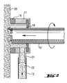
- a cooling and rinsing device 1 has a coolant and rinsing agent 2 in the form of Water in a closed reservoir 3, which with a suction pump 4 an atmosphere 5 is connected, and a closed flushing circuit 6 from Collection container 3 through a via a pressure pump 7, further through a filter 8 through a tool device 9 in the form of a core drilling device, further over parts of a tool 10 in the form of a core drill bit and further via a tool 10 assigned Collection means 11 with a suction line 12 back to the collecting container 3.
- the rinsing circuit 6 is combined with a supply circuit 13 in which the coolant and rinsing agent 2 from a large storage container 14 open to the atmosphere 5 via a storage container 3 arranged, controlled by the level, float valve 15 in the collecting container 3, further together with the flushing circuit 6 through the pressure pump 7 into the filter 8 and over a filter concentrate drain or valve 16 at the lower end of the filter 8 as contaminated coolant and flushing agent 2 gets back into the storage container 14.
- the Suction pump 4 and the pressure pump 7 are connected to the tool device 9 by a combined drive 17 combined.
- the collecting means 11 as a, a core bit as a tool 10 coaxially in Interior with radial seals 18 radially sealing, axially open on one side and at the edge with axial seals 19 axially sealing against a surface 20 to be machined Torus executed with a connection 21 for the suction line 12, through which the removed material 22 contaminated coolant and detergent 2 is discharged.
Landscapes
- Engineering & Computer Science (AREA)
- Mechanical Engineering (AREA)
- Mining & Mineral Resources (AREA)
- Geology (AREA)
- Life Sciences & Earth Sciences (AREA)
- Fluid Mechanics (AREA)
- Environmental & Geological Engineering (AREA)
- Physics & Mathematics (AREA)
- General Life Sciences & Earth Sciences (AREA)
- Geochemistry & Mineralogy (AREA)
- Auxiliary Devices For Machine Tools (AREA)
- Processing Of Stones Or Stones Resemblance Materials (AREA)
- Cleaning By Liquid Or Steam (AREA)
Abstract
Description
Claims (10)
- Kühl- und Spülvorrichtung für ein Werkzeug (10) mit einem Kühl- und Spülmittel (2) in einem geschlossenen Sammelbehälter (3), welcher mit einer Saugpumpe (4) verbundenen ist und mit einem geschlossenen Spülkreislauf (6) vom Sammelbehälter (3) durch einen über eine Druckpumpe (7) angeschlossenen Filter (8) und durch ein dem Werkzeug (10) zugeordnetes Auffangmittel (11) mit einer Saugleitung (12) zurück zu dem Sammelbehälter (3), dadurch gekennzeichnet, dass dem Spülkreislauf (6) ein Vorratskreislauf (13) für das Kühl- und Spülmittel (2) kombiniert zugeordnet ist, bei welchem ein Vorratsbehälter (14) über ein im Sammelbehälter (3) angeordnetes Schwimmerventil (15) mit dem Sammelbehälter (3), sowie an anderer Stelle des Spülkreislaufes (6) über ein Ventil (16) mit dem Vorratsbehälter (14) verbunden ist.
- Kühl- und Spülvorrichtung nach Anspruch 1, dadurch gekennzeichnet, dass das Ventil (16) als Filterkonzentratabfluss am unteren Ende des Filters (8) ausgeführt ist.
- Kühl- und Spülvorrichtung nach Anspruch 1 oder Anspruch 2, dadurch gekennzeichnet, dass die Saugpumpe (4) mit einer Atmosphäre (5) verbundenen ist, zu welcher der Vorratsbehälter (14) offen ist.
- Kühl- und Spülvorrichtung nach einem der vorherigen Ansprüche, dadurch gekennzeichnet, dass ein Werkzeuggerät (9) zwischen dem Filter (8) und dem Werkzeug (10) in den Spülkreislauf (6) integriert ist.
- Kühl- und Spülvorrichtung nach einem der vorherigen Ansprüche, dadurch gekennzeichnet, dass die Saugpumpe (4) und die Druckpumpe (7) durch einen gemeinsamen Antrieb (17) kombiniert sind, welcher optional mit dem Antrieb des Werkzeuggerätes (9) kombiniert ist.
- Kühl- und Spülvorrichtung nach einem der vorherigen Ansprüche, dadurch gekennzeichnet, dass das Werkzeuggerät (9) den Sammelbehälter (3) und optional den Vorratsbehälter (14) beinhaltet.
- Kühl- und Spülvorrichtung nach einem der vorherigen Ansprüche, dadurch gekennzeichnet, dass das Werkzeuggerät (9) als Kernbohrgerät und das Werkzeug (10) als eine Kernbohrkrone ausgeführt ist.
- Kühl- und Spülvorrichtung nach einem der vorherigen Ansprüche, dadurch gekennzeichnet, dass der Sammelbehälter (3) schwimmbar auf dem Kühl- und Spülmittel (2) des Vorratsbehälters (14) ausgeführt ist.
- Kühl- und Spülvorrichtung nach einem der vorherigen Ansprüche, dadurch gekennzeichnet, dass das Auffangmittel (11) als ein, ein Werkzeug (10) koaxial im Inneren radial dichtend aufnehmender, einseitig axial offener und am Rand axial gegen eine Fläche (20) dichtender Torus mit einem Anschluss (21) für eine Saugleitung (12) ausgeführt ist.
- Kühl- und Spülvorrichtung nach einem der vorherigen Ansprüche, dadurch gekennzeichnet, dass das Kühl- und Spülmittel (2) Wasser ist.
Applications Claiming Priority (2)
| Application Number | Priority Date | Filing Date | Title |
|---|---|---|---|
| DE10043418A DE10043418A1 (de) | 2000-09-04 | 2000-09-04 | Kühl- und Spülvorrichtung für Werkzeuge zur Bearbeitung von Gestein |
| DE10043418 | 2000-09-04 |
Publications (2)
| Publication Number | Publication Date |
|---|---|
| EP1193026A1 true EP1193026A1 (de) | 2002-04-03 |
| EP1193026B1 EP1193026B1 (de) | 2006-06-14 |
Family
ID=7654840
Family Applications (1)
| Application Number | Title | Priority Date | Filing Date |
|---|---|---|---|
| EP01810815A Expired - Lifetime EP1193026B1 (de) | 2000-09-04 | 2001-08-22 | Kühl- und Spülvorrichtung für Werkzeuge zur Bearbeitung von Gestein |
Country Status (4)
| Country | Link |
|---|---|
| US (1) | US6712162B2 (de) |
| EP (1) | EP1193026B1 (de) |
| AT (1) | ATE329727T1 (de) |
| DE (2) | DE10043418A1 (de) |
Cited By (9)
| Publication number | Priority date | Publication date | Assignee | Title |
|---|---|---|---|---|
| GB2386851A (en) * | 2002-03-29 | 2003-10-01 | Filterwek Mann & Hummel Gmbh | Overhead return piping system |
| EP1386706A1 (de) * | 2002-07-29 | 2004-02-04 | HILTI Aktiengesellschaft | Spülflüssigkeitsaufbereitungsgerät |
| EP1671769A1 (de) * | 2004-12-17 | 2006-06-21 | Silvano Coccoli | Kernbohrgerät mit Rückgewinnung für Kühlflüssigkeiten |
| CN102133719A (zh) * | 2010-01-22 | 2011-07-27 | 兄弟工业株式会社 | 工具清洗装置 |
| CN107127639A (zh) * | 2017-06-01 | 2017-09-05 | 安徽吉乃尔电器科技有限公司 | 一种全自动打孔倒角攻牙机的冷却油循环装置 |
| EP3632638A1 (de) | 2018-10-01 | 2020-04-08 | Hilti Aktiengesellschaft | Absaugvorrichtung für eine kernbohreinrichtung |
| CN113019281A (zh) * | 2021-04-22 | 2021-06-25 | 南京绿沁信息科技有限公司 | 一种抗菌肽饲料添加剂制备生产线 |
| EP4194169A4 (de) * | 2020-08-06 | 2024-10-30 | Kabushiki Kaisha Miyanaga | Flüssigkeitszirkulationssystem und damit ausgestattetes bohrsystem |
| US12194583B2 (en) | 2018-10-01 | 2025-01-14 | Hilti Aktiengesellschaft | Extraction device for a core drill |
Families Citing this family (14)
| Publication number | Priority date | Publication date | Assignee | Title |
|---|---|---|---|---|
| US6666286B2 (en) * | 2001-12-20 | 2003-12-23 | Goei Co., Ltd. | Fluid circulating apparatus for drill |
| NL1022937C1 (nl) * | 2003-03-17 | 2003-07-15 | Jan Hendrik Westenberg | Sleuvenfreesmachine voor het verzinken van leidingen in muren. |
| SE0400735D0 (sv) * | 2004-03-23 | 2004-03-23 | Electrolux Ab | Water and slurry collector |
| KR100692710B1 (ko) | 2005-07-01 | 2007-03-09 | 현대자동차주식회사 | 가공기계용 쿨런트 순환시스템 |
| SE0502609L (sv) * | 2005-11-28 | 2007-05-29 | Husqvarna Ab | Vattenuppsamlingsanordning samt kärnborrningsaggregat med sådan anordning |
| US9218997B2 (en) * | 2008-11-06 | 2015-12-22 | Applied Materials, Inc. | Electrostatic chuck having reduced arcing |
| CN104339459B (zh) * | 2013-08-02 | 2016-08-10 | 南京德朔实业有限公司 | 台型切割机 |
| CN206458363U (zh) * | 2014-03-07 | 2017-09-01 | R.J.葛兹平克私人有限公司 | 钻井液收集设备 |
| US20170248324A1 (en) * | 2016-02-25 | 2017-08-31 | Eveli Co., Ltd. | Heating device for hot water mat |
| AU2018312343A1 (en) | 2017-07-31 | 2020-02-13 | Milwaukee Electric Tool Corporation | Rotary power tool |
| JP7276832B2 (ja) * | 2019-05-31 | 2023-05-18 | 株式会社呉英製作所 | 携帯式循環ろ過装置 |
| JP6738942B1 (ja) * | 2019-06-24 | 2020-08-12 | Dmg森精機株式会社 | スラッジの処理装置及びスラッジ処理システム工作機械 |
| US20220331887A1 (en) * | 2019-10-07 | 2022-10-20 | Hilti Aktiengesellschaft | Systems and methods for feedback features within power tools |
| CN114734295A (zh) * | 2022-03-21 | 2022-07-12 | 刘丽华 | 一种具有清洗功能的数控机床设备 |
Citations (5)
| Publication number | Priority date | Publication date | Assignee | Title |
|---|---|---|---|---|
| DE1130255B (de) * | 1957-07-12 | 1962-05-24 | Lehfeldt & Co G M B H Dr | Verfahren und Vorrichtung zur Steigerung der Bohrgeschwindigkeit von Bearbeitungsmaschinen, insbesondere von Ultraschallbohrmaschinen |
| US4325663A (en) * | 1977-10-10 | 1982-04-20 | Alfa-Laval Ab | Arrangement for cleaning cutting fluid |
| DE3545328A1 (de) * | 1985-12-20 | 1987-06-25 | Hilti Ag | Vorrichtung zum trennen einer spuelfluessigkeit von feststoffen |
| DE4223832A1 (de) * | 1992-05-15 | 1994-01-27 | Ona Electro Erosion | Filtrationssystem für Flüssigkeiten mit Schwebeteilchen |
| EP0941828A2 (de) * | 1998-03-13 | 1999-09-15 | HILTI Aktiengesellschaft | Saug- und Austraggerät für eine Spülflüssigkeit |
Family Cites Families (4)
| Publication number | Priority date | Publication date | Assignee | Title |
|---|---|---|---|---|
| US2786652A (en) * | 1954-12-20 | 1957-03-26 | Norman C Wells | Bottom hole pressure control in well drilling |
| US2941783A (en) * | 1957-07-15 | 1960-06-21 | Phillips Petroleum Co | Hydraulic earth boring and cyclone separation system |
| US5497839A (en) * | 1992-04-01 | 1996-03-12 | Sds Pty Ltd. | Liquid-driven downhole hammer drill |
| GB2278864B (en) * | 1993-06-10 | 1996-07-17 | James Leslie Dallas | System for retrieving waste drilling mud |
-
2000
- 2000-09-04 DE DE10043418A patent/DE10043418A1/de not_active Withdrawn
-
2001
- 2001-08-22 AT AT01810815T patent/ATE329727T1/de active
- 2001-08-22 DE DE50110128T patent/DE50110128D1/de not_active Expired - Lifetime
- 2001-08-22 EP EP01810815A patent/EP1193026B1/de not_active Expired - Lifetime
- 2001-08-29 US US09/942,379 patent/US6712162B2/en not_active Expired - Lifetime
Patent Citations (5)
| Publication number | Priority date | Publication date | Assignee | Title |
|---|---|---|---|---|
| DE1130255B (de) * | 1957-07-12 | 1962-05-24 | Lehfeldt & Co G M B H Dr | Verfahren und Vorrichtung zur Steigerung der Bohrgeschwindigkeit von Bearbeitungsmaschinen, insbesondere von Ultraschallbohrmaschinen |
| US4325663A (en) * | 1977-10-10 | 1982-04-20 | Alfa-Laval Ab | Arrangement for cleaning cutting fluid |
| DE3545328A1 (de) * | 1985-12-20 | 1987-06-25 | Hilti Ag | Vorrichtung zum trennen einer spuelfluessigkeit von feststoffen |
| DE4223832A1 (de) * | 1992-05-15 | 1994-01-27 | Ona Electro Erosion | Filtrationssystem für Flüssigkeiten mit Schwebeteilchen |
| EP0941828A2 (de) * | 1998-03-13 | 1999-09-15 | HILTI Aktiengesellschaft | Saug- und Austraggerät für eine Spülflüssigkeit |
Cited By (16)
| Publication number | Priority date | Publication date | Assignee | Title |
|---|---|---|---|---|
| GB2386851A (en) * | 2002-03-29 | 2003-10-01 | Filterwek Mann & Hummel Gmbh | Overhead return piping system |
| GB2386851B (en) * | 2002-03-29 | 2005-08-17 | Filterwek Mann & Hummel Gmbh | Overhead return piping system |
| EP1386706A1 (de) * | 2002-07-29 | 2004-02-04 | HILTI Aktiengesellschaft | Spülflüssigkeitsaufbereitungsgerät |
| US7341659B2 (en) * | 2002-07-29 | 2008-03-11 | Hilti Aktiengesellschaft | Rinsing liquid treatment device |
| EP1671769A1 (de) * | 2004-12-17 | 2006-06-21 | Silvano Coccoli | Kernbohrgerät mit Rückgewinnung für Kühlflüssigkeiten |
| CN102133719A (zh) * | 2010-01-22 | 2011-07-27 | 兄弟工业株式会社 | 工具清洗装置 |
| CN102133719B (zh) * | 2010-01-22 | 2014-07-30 | 兄弟工业株式会社 | 工具清洗装置 |
| CN107127639B (zh) * | 2017-06-01 | 2019-08-02 | 惠州市鑫诚五金制品有限公司 | 一种全自动打孔倒角攻牙机的冷却油循环装置 |
| CN107127639A (zh) * | 2017-06-01 | 2017-09-05 | 安徽吉乃尔电器科技有限公司 | 一种全自动打孔倒角攻牙机的冷却油循环装置 |
| EP3632638A1 (de) | 2018-10-01 | 2020-04-08 | Hilti Aktiengesellschaft | Absaugvorrichtung für eine kernbohreinrichtung |
| WO2020069891A1 (de) | 2018-10-01 | 2020-04-09 | Hilti Aktiengesellschaft | Absaugvorrichtung für eine kernbohreinrichtung |
| US12194547B2 (en) | 2018-10-01 | 2025-01-14 | Hilti Aktiengesellschaft | Extraction device for a core drill |
| US12194583B2 (en) | 2018-10-01 | 2025-01-14 | Hilti Aktiengesellschaft | Extraction device for a core drill |
| EP4194169A4 (de) * | 2020-08-06 | 2024-10-30 | Kabushiki Kaisha Miyanaga | Flüssigkeitszirkulationssystem und damit ausgestattetes bohrsystem |
| US12589441B2 (en) | 2020-08-06 | 2026-03-31 | Kabushiki Kaisha Miyanaga | Liquid circulation system and boring system including the same |
| CN113019281A (zh) * | 2021-04-22 | 2021-06-25 | 南京绿沁信息科技有限公司 | 一种抗菌肽饲料添加剂制备生产线 |
Also Published As
| Publication number | Publication date |
|---|---|
| EP1193026B1 (de) | 2006-06-14 |
| DE50110128D1 (de) | 2006-07-27 |
| ATE329727T1 (de) | 2006-07-15 |
| US6712162B2 (en) | 2004-03-30 |
| US20020027023A1 (en) | 2002-03-07 |
| DE10043418A1 (de) | 2002-04-18 |
Similar Documents
| Publication | Publication Date | Title |
|---|---|---|
| EP1193026B1 (de) | Kühl- und Spülvorrichtung für Werkzeuge zur Bearbeitung von Gestein | |
| DE3521510A1 (de) | Vorrichtung zur umlauffoerderung fluessigen kuehlmittels | |
| EP1970660B1 (de) | Anordnung und Verfahren zur Rückgewinnung von Wärmeenergie aus Abwässern | |
| DE102019121736B4 (de) | Geschirrspülmaschine und Verfahren zum Betrieb einer Geschirrspülmaschine | |
| DE102013211032A1 (de) | Filteranlage zum Entfernen und /oder Neutralisieren von ungelösten Ölen, Fetten und Salzen auf und in wasserhaltigen Emulsionen | |
| DE102009055011A1 (de) | Vorrichtung zur Aufbereitung einer Kühl- und Spülflüssigkeit | |
| DE3030614A1 (de) | Verfahren, insbesondere zum abscheiden von quecksilberverbindungen und quecksilberlegierungen in form fester teilchen aus einem fluidum, und geraet zur durchfuehrung des verfahrens | |
| DE8910186U1 (de) | Vorrichtung zum Entsorgen von flüssigen Medien mit Produktionsrückständen | |
| DE10310486B4 (de) | Obengeführtes Rückflussleitungssystem | |
| DE60011954T2 (de) | Vorrichung zur Deodorierung von Brillenglas-Schleifmaschinen | |
| DE102006035345B4 (de) | Mobile Flüssigkeitsfördervorrichtung für ein Werkzeuggerät | |
| EP0941828A2 (de) | Saug- und Austraggerät für eine Spülflüssigkeit | |
| DE707628C (de) | Vorrichtung zum Zufuehren von Kuehl-, Schmier- und Spuelfluessigkeit an Werkzeugmaschinen mit umlaufenden Werkzeugen | |
| EP0515451A1 (de) | Aufbereitungssystem für kühlschmierstoffe | |
| DE2232622C3 (de) | Klosettspülvorrichtung mit Umlauf der Reinigungsflüssigkeit | |
| EP2335895A1 (de) | Vorrichtung und Verfahren zur Aufbereitung einer Kühl- und Spülflüssigkeit | |
| DE10234407A1 (de) | Spülflüssigkeitsaufbereitungsgerät | |
| DE503969C (de) | Einrichtung zum Absaugen von Gemischen aus Abfallstoffen und Abwaessern aus mehreren Sinkgruben mit gemeinsamer Abflussleitung | |
| DE3740211A1 (de) | Verfahren zur wiederaufbereitung von verschmutzten alkalischen gleitschleifwaessern von gleitschleifanlagen | |
| DE74104C (de) | Gläserspül- und Bürstmaschine | |
| DE4417066A1 (de) | Spülvorrichtung | |
| DE20110224U1 (de) | Gerät zum Reinigen einer Spülflüssigkeit | |
| DE10210983B4 (de) | Industrielle Reinigungsanlage mit einer Selektionsvorrichtung für gebrauchte Reinigungsflüssigkeiten | |
| DE102023131817A1 (de) | Schneidflüssigkeitsversorgungssystem | |
| DE19957937A1 (de) | Gerät zur Reinigung von Kühlschmieremulsion |
Legal Events
| Date | Code | Title | Description |
|---|---|---|---|
| PUAI | Public reference made under article 153(3) epc to a published international application that has entered the european phase |
Free format text: ORIGINAL CODE: 0009012 |
|
| AK | Designated contracting states |
Kind code of ref document: A1 Designated state(s): AT BE CH CY DE DK ES FI FR GB GR IE IT LI LU MC NL PT SE TR |
|
| AX | Request for extension of the european patent |
Free format text: AL;LT;LV;MK;RO;SI |
|
| 17P | Request for examination filed |
Effective date: 20021004 |
|
| AKX | Designation fees paid |
Free format text: AT BE CH CY DE DK ES FI FR GB GR IE IT LI LU MC NL PT SE TR |
|
| GRAP | Despatch of communication of intention to grant a patent |
Free format text: ORIGINAL CODE: EPIDOSNIGR1 |
|
| GRAS | Grant fee paid |
Free format text: ORIGINAL CODE: EPIDOSNIGR3 |
|
| GRAA | (expected) grant |
Free format text: ORIGINAL CODE: 0009210 |
|
| AK | Designated contracting states |
Kind code of ref document: B1 Designated state(s): AT BE CH CY DE DK ES FI FR GB GR IE IT LI LU MC NL PT SE TR |
|
| PG25 | Lapsed in a contracting state [announced via postgrant information from national office to epo] |
Ref country code: IT Free format text: LAPSE BECAUSE OF FAILURE TO SUBMIT A TRANSLATION OF THE DESCRIPTION OR TO PAY THE FEE WITHIN THE PRESCRIBED TIME-LIMIT;WARNING: LAPSES OF ITALIAN PATENTS WITH EFFECTIVE DATE BEFORE 2007 MAY HAVE OCCURRED AT ANY TIME BEFORE 2007. THE CORRECT EFFECTIVE DATE MAY BE DIFFERENT FROM THE ONE RECORDED. Effective date: 20060614 Ref country code: FI Free format text: LAPSE BECAUSE OF FAILURE TO SUBMIT A TRANSLATION OF THE DESCRIPTION OR TO PAY THE FEE WITHIN THE PRESCRIBED TIME-LIMIT Effective date: 20060614 Ref country code: IE Free format text: LAPSE BECAUSE OF FAILURE TO SUBMIT A TRANSLATION OF THE DESCRIPTION OR TO PAY THE FEE WITHIN THE PRESCRIBED TIME-LIMIT Effective date: 20060614 |
|
| REG | Reference to a national code |
Ref country code: GB Ref legal event code: FG4D Free format text: NOT ENGLISH |
|
| REG | Reference to a national code |
Ref country code: CH Ref legal event code: EP |
|
| REG | Reference to a national code |
Ref country code: SE Ref legal event code: TRGR |
|
| REG | Reference to a national code |
Ref country code: IE Ref legal event code: FG4D Free format text: LANGUAGE OF EP DOCUMENT: GERMAN |
|
| REF | Corresponds to: |
Ref document number: 50110128 Country of ref document: DE Date of ref document: 20060727 Kind code of ref document: P |
|
| PG25 | Lapsed in a contracting state [announced via postgrant information from national office to epo] |
Ref country code: MC Free format text: LAPSE BECAUSE OF NON-PAYMENT OF DUE FEES Effective date: 20060831 |
|
| GBT | Gb: translation of ep patent filed (gb section 77(6)(a)/1977) |
Effective date: 20060822 |
|
| PG25 | Lapsed in a contracting state [announced via postgrant information from national office to epo] |
Ref country code: DK Free format text: LAPSE BECAUSE OF FAILURE TO SUBMIT A TRANSLATION OF THE DESCRIPTION OR TO PAY THE FEE WITHIN THE PRESCRIBED TIME-LIMIT Effective date: 20060914 |
|
| PG25 | Lapsed in a contracting state [announced via postgrant information from national office to epo] |
Ref country code: ES Free format text: LAPSE BECAUSE OF FAILURE TO SUBMIT A TRANSLATION OF THE DESCRIPTION OR TO PAY THE FEE WITHIN THE PRESCRIBED TIME-LIMIT Effective date: 20060925 |
|
| PG25 | Lapsed in a contracting state [announced via postgrant information from national office to epo] |
Ref country code: PT Free format text: LAPSE BECAUSE OF FAILURE TO SUBMIT A TRANSLATION OF THE DESCRIPTION OR TO PAY THE FEE WITHIN THE PRESCRIBED TIME-LIMIT Effective date: 20061114 |
|
| ET | Fr: translation filed | ||
| REG | Reference to a national code |
Ref country code: IE Ref legal event code: FD4D |
|
| PLBE | No opposition filed within time limit |
Free format text: ORIGINAL CODE: 0009261 |
|
| STAA | Information on the status of an ep patent application or granted ep patent |
Free format text: STATUS: NO OPPOSITION FILED WITHIN TIME LIMIT |
|
| 26N | No opposition filed |
Effective date: 20070315 |
|
| PG25 | Lapsed in a contracting state [announced via postgrant information from national office to epo] |
Ref country code: GR Free format text: LAPSE BECAUSE OF FAILURE TO SUBMIT A TRANSLATION OF THE DESCRIPTION OR TO PAY THE FEE WITHIN THE PRESCRIBED TIME-LIMIT Effective date: 20060915 |
|
| PG25 | Lapsed in a contracting state [announced via postgrant information from national office to epo] |
Ref country code: TR Free format text: LAPSE BECAUSE OF FAILURE TO SUBMIT A TRANSLATION OF THE DESCRIPTION OR TO PAY THE FEE WITHIN THE PRESCRIBED TIME-LIMIT Effective date: 20060614 Ref country code: LU Free format text: LAPSE BECAUSE OF NON-PAYMENT OF DUE FEES Effective date: 20060822 |
|
| PG25 | Lapsed in a contracting state [announced via postgrant information from national office to epo] |
Ref country code: CY Free format text: LAPSE BECAUSE OF FAILURE TO SUBMIT A TRANSLATION OF THE DESCRIPTION OR TO PAY THE FEE WITHIN THE PRESCRIBED TIME-LIMIT Effective date: 20060614 |
|
| REG | Reference to a national code |
Ref country code: FR Ref legal event code: PLFP Year of fee payment: 16 |
|
| REG | Reference to a national code |
Ref country code: FR Ref legal event code: PLFP Year of fee payment: 17 |
|
| REG | Reference to a national code |
Ref country code: FR Ref legal event code: PLFP Year of fee payment: 18 |
|
| PGFP | Annual fee paid to national office [announced via postgrant information from national office to epo] |
Ref country code: NL Payment date: 20190821 Year of fee payment: 19 |
|
| PGFP | Annual fee paid to national office [announced via postgrant information from national office to epo] |
Ref country code: DE Payment date: 20190822 Year of fee payment: 19 Ref country code: FR Payment date: 20190822 Year of fee payment: 19 Ref country code: SE Payment date: 20190821 Year of fee payment: 19 |
|
| PGFP | Annual fee paid to national office [announced via postgrant information from national office to epo] |
Ref country code: BE Payment date: 20190821 Year of fee payment: 19 |
|
| PGFP | Annual fee paid to national office [announced via postgrant information from national office to epo] |
Ref country code: AT Payment date: 20190822 Year of fee payment: 19 Ref country code: GB Payment date: 20190821 Year of fee payment: 19 |
|
| PGFP | Annual fee paid to national office [announced via postgrant information from national office to epo] |
Ref country code: CH Payment date: 20190821 Year of fee payment: 19 |
|
| REG | Reference to a national code |
Ref country code: DE Ref legal event code: R119 Ref document number: 50110128 Country of ref document: DE |
|
| REG | Reference to a national code |
Ref country code: SE Ref legal event code: EUG |
|
| REG | Reference to a national code |
Ref country code: CH Ref legal event code: PL |
|
| REG | Reference to a national code |
Ref country code: NL Ref legal event code: MM Effective date: 20200901 |
|
| REG | Reference to a national code |
Ref country code: AT Ref legal event code: MM01 Ref document number: 329727 Country of ref document: AT Kind code of ref document: T Effective date: 20200822 |
|
| GBPC | Gb: european patent ceased through non-payment of renewal fee |
Effective date: 20200822 |
|
| PG25 | Lapsed in a contracting state [announced via postgrant information from national office to epo] |
Ref country code: LI Free format text: LAPSE BECAUSE OF NON-PAYMENT OF DUE FEES Effective date: 20200831 Ref country code: CH Free format text: LAPSE BECAUSE OF NON-PAYMENT OF DUE FEES Effective date: 20200831 |
|
| REG | Reference to a national code |
Ref country code: BE Ref legal event code: MM Effective date: 20200831 |
|
| PG25 | Lapsed in a contracting state [announced via postgrant information from national office to epo] |
Ref country code: SE Free format text: LAPSE BECAUSE OF NON-PAYMENT OF DUE FEES Effective date: 20200823 Ref country code: AT Free format text: LAPSE BECAUSE OF NON-PAYMENT OF DUE FEES Effective date: 20200822 |
|
| PG25 | Lapsed in a contracting state [announced via postgrant information from national office to epo] |
Ref country code: DE Free format text: LAPSE BECAUSE OF NON-PAYMENT OF DUE FEES Effective date: 20210302 Ref country code: FR Free format text: LAPSE BECAUSE OF NON-PAYMENT OF DUE FEES Effective date: 20200831 |
|
| PG25 | Lapsed in a contracting state [announced via postgrant information from national office to epo] |
Ref country code: BE Free format text: LAPSE BECAUSE OF NON-PAYMENT OF DUE FEES Effective date: 20200831 Ref country code: GB Free format text: LAPSE BECAUSE OF NON-PAYMENT OF DUE FEES Effective date: 20200822 |
|
| PG25 | Lapsed in a contracting state [announced via postgrant information from national office to epo] |
Ref country code: NL Free format text: LAPSE BECAUSE OF NON-PAYMENT OF DUE FEES Effective date: 20200901 |