EP1191142A2 - Trockenwalze zum Trocknen einer Materialbahn - Google Patents
Trockenwalze zum Trocknen einer Materialbahn Download PDFInfo
- Publication number
- EP1191142A2 EP1191142A2 EP01117824A EP01117824A EP1191142A2 EP 1191142 A2 EP1191142 A2 EP 1191142A2 EP 01117824 A EP01117824 A EP 01117824A EP 01117824 A EP01117824 A EP 01117824A EP 1191142 A2 EP1191142 A2 EP 1191142A2
- Authority
- EP
- European Patent Office
- Prior art keywords
- roller
- roll according
- material web
- gas
- roll
- Prior art date
- Legal status (The legal status is an assumption and is not a legal conclusion. Google has not performed a legal analysis and makes no representation as to the accuracy of the status listed.)
- Granted
Links
Images


Classifications
-
- D—TEXTILES; PAPER
- D21—PAPER-MAKING; PRODUCTION OF CELLULOSE
- D21F—PAPER-MAKING MACHINES; METHODS OF PRODUCING PAPER THEREON
- D21F5/00—Dryer section of machines for making continuous webs of paper
- D21F5/18—Drying webs by hot air
- D21F5/182—Drying webs by hot air through perforated cylinders
-
- D—TEXTILES; PAPER
- D21—PAPER-MAKING; PRODUCTION OF CELLULOSE
- D21F—PAPER-MAKING MACHINES; METHODS OF PRODUCING PAPER THEREON
- D21F3/00—Press section of machines for making continuous webs of paper
- D21F3/02—Wet presses
- D21F3/10—Suction rolls, e.g. couch rolls
Definitions
- the present invention relates to a roller for use in the dryer section a machine for producing a material web, in particular for guiding and holding a drying gas Paper web, with a jacket, over which the material web during operation of the roller, partially wrapping the roller and in which gas passage openings are provided, and means for conveying gas through the roller jacket.
- Such rollers are used, for example, as suction guide rollers in dryer sections used, in which the material web by means of impingement drying, blowing the material web with drying air. By vacuuming the suction guide roller, the material web on the roller held and can be guided through this in the desired manner.
- the interior of the suction guide roll is hollow and is customary connected to a suction device via the roller bearings. This requires relatively large trunnions and corresponding bearing supports for the suction guide roller.
- the invention has for its object a roller of the aforementioned Specify which does not have these disadvantages.
- the start-up phase should be shortened.
- the flow rate should also of the gas optimized and a simple construction of the Roller can be reached.
- the suctioned volume of the Roll can be significantly reduced compared to known rolls.
- the vacuumed room can only about 10 to about 15% of the total Volume of the roller.
- the establishment of a desired negative pressure can be done in a shorter time than with known rollers.
- the flow rate of the extracted air can the size of the space can be brought to a desired level. This results in particularly short reaction times when performing a material web, for example after a production interruption because of a web break or the like.
- roller is relatively can have a simple structure, since the main part of the roller only has a supporting and supporting function.
- the roller according to the invention is therefore used in particular as a suction guide roller used to guide and hold a material web in a dryer section, in which the material web is dried by impingement drying becomes.
- the roller according to the invention can also be used for through-flow drying a material web are used, in which a Drying gas, in particular air, is conveyed through the material web becomes.
- the drying gas can come in particular from the outside through the material web into the space between the invention Roller are promoted.
- the roller is preferred as a suction roller formed by a suction device connected to the intermediate space is.
- a blow zone is provided for the outer roll shell with the material web be, in particular by a blow box is arranged there.
- a drying gas can pass through the material web from the outside to be promoted in the gap. It is also possible such a blowing zone with one connected to the intermediate space To combine suction device.
- this is preferably on the front connected the gap. This will construct the Simplified roller and avoided a large diameter of the bearings. Especially it is preferred if one aligned with the intermediate space Suction box is provided. Connection lines between the Suction device and the space are therefore unnecessary.
- the roller according to the invention can also be used for promotion of the drying gas from the intermediate space through the material web be trained outside.
- the material web is by means of a Dryer screen pressed against the roller.
- the roller can preferably be designed as a blowing roller by a blower is connected to the intermediate space. Also in this case, the blowing device is preferably on the end face of the intermediate space connected to achieve a simple construction of the roller.
- a suction zone is set up in the wrapping area of the roll shell his.
- a suction box can be arranged there. On too this way drying gas can pass from the space through the web be promoted externally.
- a suction zone can also be used a blowing device connected to the intermediate space combined his.
- the blow and suction boxes are each sealed to the outside, for example with sealing brushes or scraper. Furthermore, it can preferably be made from the material web wrapped area of the roller fixed in the space Covers for the passage openings of the outer roller shell be provided. Leakage flows are also avoided in this way and thus improves the effectiveness of the device.
- To support the two roller shells is preferably a along the Central carrier extending longitudinal axis provided on which the two roller shells are supported rotatably about their longitudinal axis.
- a particularly advantageous construction results when inside the Inner jacket spoke-like supporting elements are arranged, via which the inner jacket is supported on the carrier.
- the outer jacket can on the other hand, are preferably carried by the inner jacket.
- the size of the space can preferably be appropriate a desired flow rate of the gas can be selected.
- a smaller one can make a higher one Flow rate and faster response time achieved become.
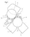
- the section of a dryer section shown in FIG. 1 comprises a first one Roller 1 and a second roller 2, over which a material web 3 in Direction of arrow I is meandering.
- the two rollers 1 and 2 are each designed as a suction roller and not in detail here shown suction device connected. Both rollers 1, 2 are also each surrounded by a sieve 4, each between the web 3 and roller 1, 2 is arranged.
- the screen 4 can, other than shown, also arranged firmly on the rollers 1, 2, for example these are pulled up or shrunk.
- blowing hoods 5 are arranged, over which the material web 3 can be charged with air for impingement drying.
- the hood 5 is made in one part, in the case of the roller 2 in two parts.
- the roller 1 comprises, as can be seen from FIGS. 2 and 3, a roller jacket 6 for guiding the material web 3 and one in Inside of the roll shell 6 arranged inner shell 7. Between the outer Roller jacket 6 and inner jacket 7 is an annular space 8 formed, which is opposite the interior 9 of the inner shell 7 is sealed gas-tight. For this purpose, the inner jacket 7 is gas-tight and provided with panels 10 on its end faces.
- the outer roll shell 6, in contrast, has gas passage openings, in particular in the form of holes 14. In this way there is the gap 8 in connection with the outside space.
- the inner jacket 7 is supported by spoke-like support elements 11 a carrier 12 extending along the roll longitudinal axis II around the Longitudinal roller axis II rotatable.
- Fig. 4 shows the cross section of the spoke-like Support elements 11.
- the outer roll shell 6 is through the inner jacket 7 worn.
- the size of the space 8 is in particular in accordance with a desired one Flow rate of the gas selected, for example so that the volume of the space 8 is about 10 to about 15% of the volume of the entire interior of the roller.
- the gap 8 is connected to a suction device, in particular to a suction box, which are provided in alignment with the space 8 at the end can, but is not shown here.
- the space 8 can also be connected to a blowing device, which can be designed accordingly, be connected, in particular if the roller 1 for throughflow drying of a material web is used.
- a blowing device which can be designed accordingly, be connected, in particular if the roller 1 for throughflow drying of a material web is used.
- blowing and suction devices as well as the blowing and suction boxes are each sealed by seals against leakage currents. Moreover can be fixed in the non-wrapped areas of the rollers 1 and 2 Covers for the passage openings 14 in the outer roll shell 6 may be provided.
- the result is a roller with short reaction times when building one desired overpressure or underpressure, which is particularly the case during the performance process after an interruption in production by tearing off the material web or the like is advantageous.
- the suctioned or pressurized Space of the roller can be optimal in terms of its size Flow rate of the gas can be designed. By reduction the majority of the roller on a supporting function can Roller can also be made easier and lighter. The total mass the roller can be reduced.
Landscapes
- Drying Of Solid Materials (AREA)
- Paper (AREA)
Abstract
Description
- Fig. 1
- einen Abschnitt einer Trockenpartie mit erfindungsgemäßen Walzen,
- Fig. 2
- einen Längsschnitt durch eine erfindungsgemäße Walze,
- Fig. 3
- einen Querschnitt durch die Walze von Fig. 2, und
- Fig. 4
- einen Schnitt gemäß Linie A-A in Fig. 2.
- 1
- Walze
- 2
- Walze
- 3
- Materialbahn
- 4
- Sieb
- 5
- Blashaube
- 6
- Walzenmantel
- 7
- Innenmantel
- 8
- Zwischenraum
- 9
- Innenraum von 7
- 10
- Seitenverkleidung
- 11
- Stützelement
- 12
- zentraler Träger
- 13
- Lagerzapfen
- 14
- Durchtrittsöffnung
- I
- Bahnlaufrichtung
- II
- Walzenlängsachse
Claims (21)
- Walze zur Verwendung in der Trockenpartie einer Maschine zur Herstellung einer Materialbahn (3), insbesondere zum Führen und Halten einer mittels eines Trocknungsgases beaufschlagten Papierbahn, mit einem Mantel (6), über welchen die Materialbahn (3) beim Betrieb der Walze (1), die Walze (1) dabei teilweise umschlingend, geführt ist und in welchem Gasdurchtrittsöffnungen (14) vorgesehen sind, und Mitteln zum Fördern von Gas durch den Walzenmantel (6),
dadurch gekennzeichnet, daß im Inneren des Walzenmantels (6) ein zweiter, gasdichter Mantel (7) vorgesehen ist, der mit dem äußeren Walzenmantel (6) einen Ringraum (8) bildet, und daß der Ringraum (8) gegenüber dem Inneren (9) des Innenmantels (7) gasdicht abgedichtet ist. - Walze nach Anspruch 1,
dadurch gekennzeichnet, daß das Gas von außen durch die Materialbahn (3) in den Zwischenraum (8) gefördert wird. - Walze nach Anspruch 1 oder 2,
dadurch gekennzeichnet, daß an den Zwischenraum (8) eine Saugvorrichtung angeschlossen ist. - Walze nach Anspruch 3,
dadurch gekennzeichnet, daß die Saugvorrichtung stirnseitig an den Zwischenraum (8) angeschlossen ist. - Walze nach Anspruch 4,
dadurch gekennzeichnet, daß als Saugvorrichtung ein mit dem Zwischenraum (8) fluchtender Saugkasten vorgesehen ist. - Walze nach einem der vorhergehenden Ansprüche 1 bis 5,
dadurch gekennzeichnet, daß im Bereich der Umschlingung des äußeren Walzenmantels (6) mit der Materialbahn (3) eine Blaszone angeordnet ist. - Walze nach Anspruch 6,
dadurch gekennzeichnet, daß die Blaszone durch einen Blaskasten (5) gebildet wird. - Walze nach Anspruch 7,
dadurch gekennzeichnet, daß der Blaskasten (5) durch seitliche Abdichtungen, insbesondere Dichtbürsten oder Schaber gegen Verlustströmungen abgedichtet ist. - Walze nach Anspruch 1,
dadurch gekennzeichnet, daß das Gas vom Zwischenraum (8) durch die Materialbahn (3) nach außen gefördert wird. - Walze nach Anspruch 1 oder 9,
dadurch gekennzeichnet, daß an den Zwischenraum (8) eine Blasvorrichung angeschlossen ist. - Walze nach Anspruch 10,
dadurch gekennzeichnet, daß die Blasvorrichtung stirnseitig an den Zwischenraum (8) angeschlossen ist. - Walze nach Anspruch 11,
dadurch gekennzeichnet, daß als Blasvorrichtung ein mit dem Zwischenraum (8) fluchtender Blaskasten vorgesehen ist. - Walze nach einem der Ansprüche 9 bis 12,
dadurch gekennzeichnet, daß im Bereich der Umschlingung des äußeren Walzenmantels (6) mit der Materialbahn (3) eine Saugzone angeordnet ist. - Walze nach Anspruch 13,
dadurch gekennzeichnet, daß die Saugzone durch einen Saugkasten gebildet wird. - Walze nach Anspruch 14,
dadurch gekennzeichnet, daß der Saugkasten durch seitliche Abdichtungen, insbesondere Dichtbürsten oder Schaber gegen Verlustströmungen abgedichtet ist. - Walze nach einem der vorhergehenden Ansprüche,
dadurch gekennzeichnet, daß im nicht von der Materialbahn (3) umschlungenen Bereich der Walze (1) im Zwischenraum (8) feststehende Abdeckungen für die Durchtrittsöffnungen (14) des äußeren Walzenmantels (6) vorgesehen sind. - Walze nach einem der vorhergehenden Ansprüche,
dadurch gekennzeichnet, daß ein sich längs der Walzenlängsachse (II) erstreckender zentraler Träger (12) vorgesehen ist, auf welchem die beiden Walzenmäntel (6, 7) um ihre Längsachse (II) drehbar abgestützt sind. - Walze nach Anspruch 17,
dadurch gekennzeichnet, daß im Inneren (9) des Innenmantels (7) speichenartige Stützelemente (11) angeordnet sind, über welche sich der Innenmantel (7) auf dem zentralen Träger (12) abstützt. - Walze nach einem der vorhergehenden Ansprüche,
dadurch gekennzeichnet, daß der Außenmantel (6) vom Innenmantel (7) getragen wird. - Walze nach einem der vorhergehenden Ansprüche,
dadurch gekennzeichnet, daß die Größe des Zwischenraums (8) entsprechend einer gewünschten Strömungsgeschwindigkeit des Gases gewählt ist, insbesondere ca. 10 bis ca. 15 % des Volumens des gesamten Walzeninnenraums beträgt. - Walze nach einem der vorhergehenden Ansprüche,
dadurch gekennzeichnet, daß sie in Verbindung mit einem Sieb verwendet wird, welches zwischen Materialbahn (3) und Walze (1, 2) angeordnet ist.
Applications Claiming Priority (2)
| Application Number | Priority Date | Filing Date | Title |
|---|---|---|---|
| DE10047369 | 2000-09-25 | ||
| DE10047369A DE10047369A1 (de) | 2000-09-25 | 2000-09-25 | Trockenwalze zum Trocknen einer Materialbahn |
Publications (3)
| Publication Number | Publication Date |
|---|---|
| EP1191142A2 true EP1191142A2 (de) | 2002-03-27 |
| EP1191142A3 EP1191142A3 (de) | 2003-06-18 |
| EP1191142B1 EP1191142B1 (de) | 2006-09-06 |
Family
ID=7657483
Family Applications (1)
| Application Number | Title | Priority Date | Filing Date |
|---|---|---|---|
| EP01117824A Expired - Lifetime EP1191142B1 (de) | 2000-09-25 | 2001-07-21 | Trockenwalze zum Trocknen einer Materialbahn |
Country Status (4)
| Country | Link |
|---|---|
| US (1) | US6523279B2 (de) |
| EP (1) | EP1191142B1 (de) |
| CA (1) | CA2357643A1 (de) |
| DE (2) | DE10047369A1 (de) |
Families Citing this family (6)
| Publication number | Priority date | Publication date | Assignee | Title |
|---|---|---|---|---|
| US6877246B1 (en) * | 2003-12-30 | 2005-04-12 | Kimberly-Clark Worldwide, Inc. | Through-air dryer assembly |
| DE102004023321A1 (de) | 2004-05-07 | 2005-11-24 | Voith Paper Patent Gmbh | Trockenpartie in einer Maschine zur Herstellung einer Faserstoffbahn |
| EP1743069A1 (de) * | 2004-05-07 | 2007-01-17 | Voith Patent GmbH | Saugwalze in einer maschine zur herstellung einer faserstoffbahn |
| CN105627709A (zh) * | 2016-02-06 | 2016-06-01 | 上海凯赛生物技术研发中心有限公司 | 滚筒刮板干燥机 |
| DE102018102462A1 (de) * | 2018-02-05 | 2019-08-08 | Voith Patent Gmbh | Glätt- oder Presswalze |
| CN118670113B (zh) * | 2024-08-21 | 2024-11-22 | 南通瑞布纺织有限公司 | 一种穿引式纺织产品高效干燥设备 |
Family Cites Families (9)
| Publication number | Priority date | Publication date | Assignee | Title |
|---|---|---|---|---|
| DE640033C (de) * | 1934-07-23 | 1936-12-19 | Schmidt Ernst | Trockenzylinderanlage zum Trocknen von Papier |
| FR392479A (fr) * | 1959-10-26 | 1908-11-27 | Isaac Emerson Palmer | Rouleau pour faire circuler les fluides |
| US3447247A (en) * | 1967-12-18 | 1969-06-03 | Beloit Corp | Method and equipment for drying web material |
| US3541697A (en) * | 1968-08-01 | 1970-11-24 | Aer Corp | High velocity through-drying system |
| US4297794A (en) * | 1977-08-02 | 1981-11-03 | Ingersoll-Rand Company | Paper sheet dryer |
| US4364185A (en) * | 1981-04-13 | 1982-12-21 | Ingersoll-Rand Company | System for drying wet, porous webs |
| IT1198207B (it) * | 1986-11-28 | 1988-12-21 | Sperotto Rimar Spa | Essicatoio a percussione ed asprazione d'aria per macchine di trattamento tessile in continuo |
| DE3914761A1 (de) * | 1989-03-08 | 1990-11-15 | Voith Gmbh J M | Leitwalze fuer ein poroeses band, beispielsweise fuer ein trockensieb einer papiermaschine |
| US5722180A (en) * | 1996-09-04 | 1998-03-03 | Fort James Corporation | Apparatus for drying a wet paper web |
-
2000
- 2000-09-25 DE DE10047369A patent/DE10047369A1/de not_active Withdrawn
-
2001
- 2001-07-21 EP EP01117824A patent/EP1191142B1/de not_active Expired - Lifetime
- 2001-07-21 DE DE50110925T patent/DE50110925D1/de not_active Expired - Fee Related
- 2001-09-12 US US09/949,826 patent/US6523279B2/en not_active Expired - Fee Related
- 2001-09-21 CA CA002357643A patent/CA2357643A1/en not_active Abandoned
Also Published As
| Publication number | Publication date |
|---|---|
| US20020092197A1 (en) | 2002-07-18 |
| DE10047369A1 (de) | 2002-04-11 |
| EP1191142B1 (de) | 2006-09-06 |
| DE50110925D1 (de) | 2006-10-19 |
| EP1191142A3 (de) | 2003-06-18 |
| US6523279B2 (en) | 2003-02-25 |
| CA2357643A1 (en) | 2002-03-25 |
Similar Documents
| Publication | Publication Date | Title |
|---|---|---|
| DE3828743A1 (de) | Verfahren und vorrichtung in einer einsieb-trockengruppe einer papiermaschine | |
| DE60029002T2 (de) | Vorrichtung zur Trocknung einer feuchten Papierbahn | |
| DE2753201A1 (de) | Verfahren fuer die behandlung einer papierbahn in der nasspartie einer papiermaschine | |
| DE69923078T2 (de) | Trockenpartie | |
| DE4008434A1 (de) | Anordnung in einer ein-sieb-trockengruppe | |
| DE2223004A1 (de) | Vorrichtung zum Abfuehren von Foerdergut aus einer pneumatischen Foerdereinrichtung | |
| EP1205415A2 (de) | Vakuum-Bandfördervorrichtung | |
| EP1612328B2 (de) | Vorrichtung zum kontinuierlichen Trocknen einer Faserstoffbahn | |
| EP1191142B1 (de) | Trockenwalze zum Trocknen einer Materialbahn | |
| DE69018776T2 (de) | Filzführungswalze. | |
| AT394063B (de) | Trocknungsvorrichtung | |
| EP1743069A1 (de) | Saugwalze in einer maschine zur herstellung einer faserstoffbahn | |
| DE4009287B4 (de) | Verfahren und Vorrichtung zum Trocknen einer feuchten Papierbahn in einer Papiermaschinen-Trockenpartie | |
| DE19651191A1 (de) | Trockenpartie einer Maschine zur Herstellung einer Materialbahn | |
| DE69003113T2 (de) | Belüftungswalze mit temperaturausgleich. | |
| EP0608534A1 (de) | Nasspresse für eine Papiermaschine | |
| EP0769465B1 (de) | Tragwalzen-Wickelmaschine | |
| EP0711589A1 (de) | Bandfiltereinrichtung zum Ausbringen von Fremdpartikeln aus Flüssigkeitsbädern | |
| EP1088780A2 (de) | Vorrichtung zum wahlweisen Verschleissen von Blasöffnungen in Bedruckstoff führenden Leiteinrichtungen oder Stangen von Rotationsdruckmaschinen | |
| EP1749927B1 (de) | Vorrichtung zur Entwässerung einer Faserstoffbahn | |
| EP0889165A2 (de) | Saugwalze für eine Papiermaschine | |
| DE1510388B2 (de) | Geblase zum pneumatischen Fordern und Offnen von flockenfbrmigem Fasergut | |
| DE19782184B4 (de) | Walze für eine Papiermaschine, insbesondere für eine Papiertrocknungsvorrichtung, und Trocknergruppe für eine Papiermaschine | |
| EP1731665B1 (de) | Impingement-Trocknungsanordnung | |
| DE1917758A1 (de) | Vorrichtung zum Entwaessern von durchlaessigen Guetern |
Legal Events
| Date | Code | Title | Description |
|---|---|---|---|
| PUAI | Public reference made under article 153(3) epc to a published international application that has entered the european phase |
Free format text: ORIGINAL CODE: 0009012 |
|
| AK | Designated contracting states |
Kind code of ref document: A2 Designated state(s): AT BE CH CY DE DK ES FI FR GB GR IE IT LI LU MC NL PT SE TR |
|
| AX | Request for extension of the european patent |
Free format text: AL;LT;LV;MK;RO;SI |
|
| PUAL | Search report despatched |
Free format text: ORIGINAL CODE: 0009013 |
|
| AK | Designated contracting states |
Designated state(s): AT BE CH CY DE DK ES FI FR GB GR IE IT LI LU MC NL PT SE TR |
|
| AX | Request for extension of the european patent |
Extension state: AL LT LV MK RO SI |
|
| 17P | Request for examination filed |
Effective date: 20031218 |
|
| AKX | Designation fees paid |
Designated state(s): DE FI SE |
|
| GRAP | Despatch of communication of intention to grant a patent |
Free format text: ORIGINAL CODE: EPIDOSNIGR1 |
|
| GRAS | Grant fee paid |
Free format text: ORIGINAL CODE: EPIDOSNIGR3 |
|
| GRAA | (expected) grant |
Free format text: ORIGINAL CODE: 0009210 |
|
| AK | Designated contracting states |
Kind code of ref document: B1 Designated state(s): DE FI SE |
|
| RAP2 | Party data changed (patent owner data changed or rights of a patent transferred) |
Owner name: VOITH PATENT GMBH |
|
| REF | Corresponds to: |
Ref document number: 50110925 Country of ref document: DE Date of ref document: 20061019 Kind code of ref document: P |
|
| REG | Reference to a national code |
Ref country code: SE Ref legal event code: TRGR |
|
| PLBE | No opposition filed within time limit |
Free format text: ORIGINAL CODE: 0009261 |
|
| STAA | Information on the status of an ep patent application or granted ep patent |
Free format text: STATUS: NO OPPOSITION FILED WITHIN TIME LIMIT |
|
| 26N | No opposition filed |
Effective date: 20070607 |
|
| EUG | Se: european patent has lapsed | ||
| PG25 | Lapsed in a contracting state [announced via postgrant information from national office to epo] |
Ref country code: SE Free format text: LAPSE BECAUSE OF NON-PAYMENT OF DUE FEES Effective date: 20070722 Ref country code: DE Free format text: LAPSE BECAUSE OF NON-PAYMENT OF DUE FEES Effective date: 20080201 |
|
| PG25 | Lapsed in a contracting state [announced via postgrant information from national office to epo] |
Ref country code: FI Free format text: LAPSE BECAUSE OF NON-PAYMENT OF DUE FEES Effective date: 20070721 |