EP1188656A2 - Hinterradfederung eines Fahrzeuges - Google Patents
Hinterradfederung eines Fahrzeuges Download PDFInfo
- Publication number
- EP1188656A2 EP1188656A2 EP01119530A EP01119530A EP1188656A2 EP 1188656 A2 EP1188656 A2 EP 1188656A2 EP 01119530 A EP01119530 A EP 01119530A EP 01119530 A EP01119530 A EP 01119530A EP 1188656 A2 EP1188656 A2 EP 1188656A2
- Authority
- EP
- European Patent Office
- Prior art keywords
- vehicle
- rear wheel
- roll shaft
- vehicle body
- suspension system
- Prior art date
- Legal status (The legal status is an assumption and is not a legal conclusion. Google has not performed a legal analysis and makes no representation as to the accuracy of the status listed.)
- Granted
Links
Images


Classifications
-
- B—PERFORMING OPERATIONS; TRANSPORTING
- B62—LAND VEHICLES FOR TRAVELLING OTHERWISE THAN ON RAILS
- B62K—CYCLES; CYCLE FRAMES; CYCLE STEERING DEVICES; RIDER-OPERATED TERMINAL CONTROLS SPECIALLY ADAPTED FOR CYCLES; CYCLE AXLE SUSPENSIONS; CYCLE SIDE-CARS, FORECARS, OR THE LIKE
- B62K5/00—Cycles with handlebars, equipped with three or more main road wheels
- B62K5/10—Cycles with handlebars, equipped with three or more main road wheels with means for inwardly inclining the vehicle body on bends
-
- B—PERFORMING OPERATIONS; TRANSPORTING
- B62—LAND VEHICLES FOR TRAVELLING OTHERWISE THAN ON RAILS
- B62K—CYCLES; CYCLE FRAMES; CYCLE STEERING DEVICES; RIDER-OPERATED TERMINAL CONTROLS SPECIALLY ADAPTED FOR CYCLES; CYCLE AXLE SUSPENSIONS; CYCLE SIDE-CARS, FORECARS, OR THE LIKE
- B62K25/00—Axle suspensions
- B62K25/04—Axle suspensions for mounting axles resiliently on cycle frame or fork
- B62K25/12—Axle suspensions for mounting axles resiliently on cycle frame or fork with rocking arm pivoted on each fork leg
- B62K25/14—Axle suspensions for mounting axles resiliently on cycle frame or fork with rocking arm pivoted on each fork leg with single arm on each fork leg
- B62K25/20—Axle suspensions for mounting axles resiliently on cycle frame or fork with rocking arm pivoted on each fork leg with single arm on each fork leg for rear wheel
-
- B—PERFORMING OPERATIONS; TRANSPORTING
- B62—LAND VEHICLES FOR TRAVELLING OTHERWISE THAN ON RAILS
- B62K—CYCLES; CYCLE FRAMES; CYCLE STEERING DEVICES; RIDER-OPERATED TERMINAL CONTROLS SPECIALLY ADAPTED FOR CYCLES; CYCLE AXLE SUSPENSIONS; CYCLE SIDE-CARS, FORECARS, OR THE LIKE
- B62K5/00—Cycles with handlebars, equipped with three or more main road wheels
- B62K5/01—Motorcycles with four or more wheels
Definitions
- the present invention relates to a rear wheel suspension system in a vehicle suitable for attaining the reduction in weight of a vehicle and for increasing the degree of freedom in design and simple in construction.
- a swing type vehicle wherein a pair of right and left front wheels Wf, which are steered with a bar handle 2, are secured to a front portion of a body frame 1, a swing shaft 4 extending substantially horizontally in the longitudinal direction of the vehicle body is provided in a rear portion of the body frame 1, a battery supporting frame 9 is coupled to a second swing shaft 75 which is coaxial with the swing shaft 4, a power unit P is connected to the swing shaft 4 through a swing joint 6, rear wheels Wr are secured to both ends of an output shaft of the power unit P, and a rear end of the battery supporting frame 9 and both right and left ends of the power unit P are connected together using two restriction rods 74R and 74L.
- the rear wheels are steered in the same direction as the turning direction (steering direction of the front wheels) with the centrifugal force acting on the battery supporting frame 9, a heavy object, with a battery 10 mounted thereon. Due to the necessity of mounting the heavy object on the rear portion of the vehicle body, it is difficult to attain the reduction in weight of the vehicle body and the degree of freedom in weight distribution is limited. Further, it is necessary to use the restriction rods 74R, 74L and connecting members such as ball joints attached to end portions of those restriction rods, resulting in that the number of components used increases and the manufacturing cost becomes high.
- a rear wheel suspension system in a vehicle wherein a joint member is mounted in a rear portion of a vehicle body with a pair of right and rear wheels secured thereto, the joint member comprising a roll shaft extending substantially in the longitudinal direction of the vehicle body and a swing shaft extending in the transverse direction of the vehicle body, and a rear wheel support member for supporting rear wheels is connected to a rear portion of the joint member, thereby allowing the rear wheel support member to be secured to the vehicle body rollably and swingably, characterized in that the roll shaft is mounted so that a front end portion thereof is positioned lower than its rear end portion.
- the joint member is provided with a bearing for supporting the roll shaft, and a damper is disposed between the roll shaft and the bearing. Since a damper is disposed between the roll shaft and the bearing, it is possible to easily adjust the rolling rigidity of the vehicle body and rear wheel steering characteristic, whereby the vehicle drivability is improved.
- the rear wheel support member is a drive source using a rear wheel axle as an output shaft.
- a drive source such as an engine or an electric motor to serve also as a rear swing arm, whereby it is possible to reduce the number of components used and reduce the vehicle manufacturing cost.
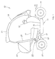
- Fig. 1 is a side view of a vehicle equipped with a rear wheel suspension system embodying the present invention.
- the vehicle is a four-wheeled vehicle, indicated at 10.
- a pair of left and right front wheels 13, 14 (the inner-side numeral 13 is not shown) to be steered with a bar handle 12 are secured rotatably to a front portion of a vehicle body 11, while a rear suspension system 30 embodying the present invention is mounted to a rear portion of the vehicle body 11.
- Numeral 16 denotes a floor step for a driver of the vehicle to put his or her feet thereon
- numeral 17 denotes a seat
- numeral 18 denotes a windscreen
- numeral 21 denotes a roof
- numeral 22 denotes a luggage box.
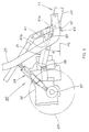
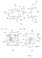
- Fig. 2 is a side view of the rear wheel suspension system according to the present invention.
- the rear wheel suspension system 30 comprises a joint member 31 attached to a rear portion of a body frame 24 which constitutes the vehicle body 11, a power unit 32 as a rear wheel support member connected to a rear end of the joint member 31 vertically swingably, the power unit comprising an engine and a power transfer unit, and rear cushion units 33 and 34 (the inner-side reference numeral 33 is not shown) mounted between the power unit 32 and the vehicle body 11 (more specifically a pole 25 secured to the body frame 24).
- Numeral 36 denotes a vertical swing shaft of the power unit 32.
- the power unit 32 has an output shaft 37 on which are mounted a pair of left and right rear wheels 26, 27 (the inner-side numeral 26 is not shown).
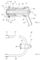
- Fig. 3 is a sectional view of the joint member used in the rear suspension system according to the present invention.
- the joint member 31 comprises a roll shaft 41 shown in Fig. 3 extending substantially in the longitudinal direction of the vehicle body for mounting the power unit 32 and the rear wheels 26, 27 rollably to the vehicle body 11 shown in Fig. 2, flanges 42 and 43 attached to a front end portion of the roll shaft 41 to attach the joint member 31 to the body frame 24 (see Fig. 2), an outer case 46 as a bearing which supports the roll shaft 41 rotatably through bushings 44 and 45, and arms 47 and 48 (the numeral 48 is not shown) secured to the outer case 46.
- the numerals 41a and 41b denote a front end portion and a rear end portion, respectively, of the roll shaft 46.
- Numeral 49 denotes an oil seal.
- Numeral 50 denotes an axis of the roll shaft 41.
- the present invention is characterized in that the roll shaft 41 is secured to the vehicle body 11 (see Fig. 2) through flanges 42 and 43 in such a manner that the front end portion 41a of the roll shaft 41 is tilted lower than the rear end portion 41b.
- the angle between a horizontal line HL and the axis 50 i.e., an inclination angle of the axis 50, is assumed to be ⁇ .
- a washer 52 is abutted against an end face of the bushing 45, one end of a collar 53 is abutted against the washer 52, and a nut 55 is disposed at the opposite end of the collar 53 through a washer 54.
- the nut 55 is threadedly engaged with the end portion of the roll shaft 41 to prevent dislodgment of the roll shaft 41 from the outer case 46.
- a lid 56 is fixed to the outer case 46 with bolts 57 and nuts 58.
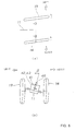
- Fig. 4 is a plan view of the joint member according to the present invention.
- Arms 47 and 48 extend sideways and backwards from an outer surface of the outer case 46 of the joint member 31 and brackets 61 for mounting the power unit 32 (see Fig. 2) are attached to rear ends of the arms 47 and 48, respectively.
- the present invention is characterized in that the rear wheel support member is the power unit 32 which uses the axle of the rear wheels 26 and 27 as the output shaft 37.
- the power unit 32 can also serve as a rear swing arm, so that it is possible to reduce the number of components and hence reduce the manufacturing cost of the four-wheeled vehicle 10 (see Fig. 1).
- Figs. 5(a) to 5(c) are schematic diagrams illustrating the vehicle related to the present invention.
- Fig. 5(a) which schematically illustrates a side face of the four-wheeled vehicle 10
- the front wheels 13 and 14 are secured to the vehicle body 11
- the flanges 42 and 43 of the joint member 31 are secured to the rear portion of the vehicle body 11
- the roll shaft 41 is secured to the flanges 42 and 43 in such a manner that its front end portion 41a is positioned lower than its rear end portion 41b
- the roll shaft 41 is supported rotatably by the outer case 46
- the arms 47 and 48 are attached to the outer case 46
- the power unit 32 is mounted to the arms 47 and 48 swingably
- the rear wheels 26 and 27 are mounted on the output shaft 37 of the power unit 32.
- Fig. 5(b) is a sectional view taken on line b-b in Fig. 5(a)
- Fig. 5(c) is a plan view of Fig. 5(a).
- Figs. 6(a) and 6(b) are a first operation diagram for explaining the operation of the rear wheel suspension system according to the present invention.
- the bar handle is, for example, turned left to steer the front wheels 13 and 14 to the left.
- Fig. 6(b) as the front wheels 13 and 14 are steered to the left, the vehicle body 11 rolls at a rolling angle of ⁇ clockwise as indicated with arrow, so that the roll shaft 41 and the outer case 46 tilt to the right reverse to the steered direction of the front wheels 13 and 14 together with the flanges 42 and 43.
- Figs. 7(a) to 7(c) are a second operation diagram for explaining the operation of the rear wheel suspension system according to the present invention, of which Fig. 7(a) is a plan view, Fig. 7(b) is a view as seen in the direction of arrow b, and Fig. 7(c) is an enlarged view of a principal portion (with flanges 42 and 43 added) of Fig. 7(b).
- Fig. 7(a) is a plan view
- Fig. 7(b) is a view as seen in the direction of arrow b
- Fig. 7(c) is an enlarged view of a principal portion (with flanges 42 and 43 added) of Fig. 7(b).
- Fig. 7(a) as the roll shaft 41 tilts to the right, since it has the inclination angle ⁇ (see Fig. 2), the rear end portion 41b of the roll shaft 41 moves to the right reverse to the steering direction.
- the roll shaft 41, as well as the outer case 46 and the arms 47 and 48, rotate relatively with respect to each other (actually, as will be described below in connection with Figs. 7(b) and 7(c), the outer case 46 and the arms 47, 48 rotate little, but the roll shaft 41 rotates).
- rear portions of the arms 47 and 48 attached to the outer case 46 move rightwards, causing a rear portion of the power unit 32 and rear portions of the rear wheels 26 and 27 to move rightwards as indicated with arrow 1 ⁇ .
- the rear wheels 26 and 27 can be steered leftwards, that is, in the same direction as that of the front wheels 13 and 14.
- the vehicle body 11 advances in the direction of arrow 2 ⁇ which is the steered direction of the front wheels 13 and 14, so that rolling at the time of wheel turn is diminished, whereby it is possible to enhance the stability of the vehicle body 11 and control the posture of the vehicle body easily.
- the front wheels 13 and 14 are steered to the right, the rear wheels 26 and 27 can be steered in the same direction as that of the front wheels, that is, to the right.
- the present invention is characterized in that the roll shaft 41 is mounted in a tilted state so as to position the front end portion 41a of the roll shaft 41 lower than the rear end portion 41b of the roll shaft.
- the rear wheels 26 and 27 can be steered in accordance with a rolling angle of the vehicle body 11; besides, since the rear wheels 26 and 27 can be steered in the same direction as a steered direction of the front wheels 13 and 14, it is possible to improve the steering stability in high-speed travel. Consequently, it is possible to easily control the posture of the vehicle body 11.
- the steering angle of the rear wheels 26 and 27 can be changed by changing the inclination angle ⁇ (see Fig. 2) of the roll shaft 41. Further, if the inclination angle ⁇ is made negative (that is, if the front end portion 41a of the roll shaft 41 is raised higher than the rear end portion 41b to tilt the roll shaft 41), the rear wheels 26 and 27 can be steered in a direction opposite to a steered direction of the front wheels 13 and 14 in accordance with a rolling angle of the vehicle body 11.
- the rear wheel steering structure is a simple mechanical structure and it is possible to reduce the manufacturing cost in comparison with that of a complicated electronically controlled type.
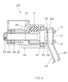
- Fig. 8 is a sectional view of a rear suspension system using a joint member according to another embodiment of the present invention.
- a joint member 64 comprises a case body 65, a roll shaft 68 inserted into the case body 65 rotatably through a pair of bearings 66 and a bearing 67, the flanges 42 and 43 secured to a front portion of the roll shaft 68, a damper 71 interposed between the case body 65 and the roll shaft 68, and a roll locking mechanism 72 which will be described in detail later.
- Numeral 73 denotes a nut for preventing dislodgment of the roll shaft 68.
- the case body 65 supports the roll shaft 68 through the bearings 66 and 67 and it is a bearing in a broad sense. (If the case body 65 bears the roll shaft 68 directly without using the bearings 66 and 67, the case body 65 is an intrinsic bearing (sliding bearing)).
- the front portion of the roll shaft 68 is formed with flange mounting surfaces 75 and 76, and flanges 42 and 43 are mounted to the flange mounting surfaces 75 and 76, respectively, with bolts 77 and nuts 78.
- a sideways projecting member 79 having a sectorial portion which projects sideways of the roll shaft 68 is serrated (or splined) to the roll shaft 68.
- Numeral 81 denotes a collar interposed between the bearings 66 and the sideways projecting member 79.
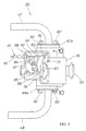
- Fig. 9 is a plan view of a joint member in the four-wheeled vehicle according to a further embodiment of the present invention, in which a lid provided on top of the joint member 64 is removed. End portions of arms 47 and 48 of the joint member 64 are provided with flanges 47a and 48a, which flanges are secured to side faces of a case body 65 with bolts 82.
- a roll locking mechanism 72 which is for locking a relative rotation between a roll shaft 68 and the case body 65, comprises a sideways projecting member 79 secured to the roll shaft 68, a first arm-like member 83 secured to the case body 65 swingably so as to lock the rotation of the sideways projecting member 79, a second arm-like member 84 secured to the case body 65 swingably so as to push the first arm-like member 83 against the sideways projecting member 79, and a link member 85 interposed between the first and second arm-like members 83, 84.
- the sideways projecting member 79 is formed with a groove 87, while the first arm-like member 83 is provided at a front end thereof with a pawl portion 88 for engagement with the groove 87 of the sideways projecting member 79.
- the second arm-like member is provided at an end portion thereof with a cable mounting portion 93 for mounting an inner cable 92 which constitutes a roll locking cable 91.
- the roll locking cable 91 functions as follows to restrict rolling of the vehicle body 11 of the four-wheeled vehicle (see Fig. 1).
- the inner cable 92 is pulled by operating an operating lever disposed near the bar handle 12 (see Fig. 1), the pawl portion 88 of the first arm-like member 83 is caught in the groove 87 of the sideways projecting member 79 to lock the rotation of the roll shaft 68 with respect to the case body 65.
- the numeral 95 denotes an outer tube as a constituent of the roll locking cable 91
- numeral 96 denotes a swing shaft of the first arm-like member
- numeral 97 denotes a swing shaft of the second arm-like member
- a pair of components indicated at 98 are nuts for mounting the roll locking cable 91 to the case body 65.
- Fig. 10 is a sectional view taken on line 10-10 in Fig. 9.
- a damper 71 used as a component of the joint member 64 comprises an elastic member receiving chamber 101 formed within the case body 65, elastic members 102 disposed at four corners of the elastic member receiving chamber 101 (for example, rubber or a soft resin is suitable as the elastic members), and a pressing member 103 disposed inside the elastic members 102 and splined to the roll shaft 68.
- the damper 71 is what is called a "Neidhart damper" in which as the pressing member 103 rotates together with the roll shaft 68, the pressing member 103 compresses the elastic members 102, thereby giving rise to a damper action.
- the present invention is characterized in that the joint member 64 is provided with the case body which supports the roll shaft 68 and that the damper 71 is disposed between the roll shaft 68 and the case body 65. Since the damper 71 is thus disposed between the roll shaft 68 and the case body 65, it is possible to easily adjust the rolling rigidity and rear wheel steering characteristic of the vehicle body 11 (see Fig. 1), whereby the drivability of the four-wheeled vehicle 10 can be improved. Further, since rolling is locked, when it is not necessary to steer the rear wheels in phase with the front wheels, it is possible to cancel steering the rear wheels and hence possible to ensure a small-turn performance.
- the rear wheel suspension system according to the present invention may be of a structure wherein the roll shaft inclination angle ⁇ is changed in accordance with the vehicle speed (more specifically, the vehicle speed is detected by a vehicle speed sensor and the roll shaft is tilted by an actuator in accordance with a signal provided from the vehicle speed sensor) or of a structure wherein the inclination angle ⁇ is changed in accordance with a steering angle of the front wheels (more specifically, the rotation of the bar handle which steers the front wheels is transmitted backward by means of a rod through a gear and the inclination angle ⁇ of the roll shaft is changed by means of a cam attached to a rear end of the rod, or a steering angle of the front wheels is detected by means of a sensor and the roll shaft is tilted by an actuator in accordance with a signal provided from the sensor).
- the damper used in the present invention is not limited to a rubber damper which utilizes rubber, but it may be a damper which utilizes fluid such as air or oil.
- the vehicle to which the invention is applied is not limited to a four-wheeled vehicle, but may be a three-wheeled vehicle comprising two front wheels and one rear wheel.
- the drive source used as the rear wheel support member in the present invention is not limited to a power unit provided with an engine, but may be an electric motor.
- a joint member 31 is mounted in a rear portion of a vehicle body 11 with a pair of left and right front wheels 13, 14 secured thereto, the joint member 31 comprising a roll shaft 41 extending substantially in the longitudinal direction of the vehicle body and a vertical swing shaft 36 extending in the transverse direction of the vehicle body, and a power unit 32 which supports rear wheels 26 and 27 is connected to a rear portion of the joint member 31, thereby allowing the power unit 32 to be secured to the vehicle body 11 rollably and swingably, the roll shaft 41 is mounted so that a front end portion 41a thereof is positioned lower than a rear end portion 41b thereof.
Applications Claiming Priority (2)
| Application Number | Priority Date | Filing Date | Title |
|---|---|---|---|
| JP2000284212 | 2000-09-19 | ||
| JP2000284212A JP4719344B2 (ja) | 2000-09-19 | 2000-09-19 | 車両の後輪懸架装置 |
Publications (3)
| Publication Number | Publication Date |
|---|---|
| EP1188656A2 true EP1188656A2 (de) | 2002-03-20 |
| EP1188656A3 EP1188656A3 (de) | 2002-08-14 |
| EP1188656B1 EP1188656B1 (de) | 2003-10-01 |
Family
ID=18768468
Family Applications (1)
| Application Number | Title | Priority Date | Filing Date |
|---|---|---|---|
| EP01119530A Expired - Lifetime EP1188656B1 (de) | 2000-09-19 | 2001-08-14 | Hinterradfederung eines Fahrzeuges |
Country Status (7)
| Country | Link |
|---|---|
| US (1) | US6766876B2 (de) |
| EP (1) | EP1188656B1 (de) |
| JP (1) | JP4719344B2 (de) |
| CN (1) | CN1267294C (de) |
| DE (1) | DE60100883T2 (de) |
| ES (1) | ES2208504T3 (de) |
| TW (1) | TW508328B (de) |
Families Citing this family (15)
| Publication number | Priority date | Publication date | Assignee | Title |
|---|---|---|---|---|
| JP2004122870A (ja) * | 2002-09-30 | 2004-04-22 | Honda Motor Co Ltd | 揺動機構付き3輪車 |
| US7290628B2 (en) * | 2004-09-02 | 2007-11-06 | American Chariot Company | Personal transport vehicle system and method |
| JP2007125917A (ja) | 2005-11-01 | 2007-05-24 | Yamaha Motor Co Ltd | 制御システムおよびそれを備えた自動二輪車 |
| JP5521994B2 (ja) * | 2010-06-25 | 2014-06-18 | 株式会社エクォス・リサーチ | 車両 |
| JP5648256B2 (ja) * | 2010-12-22 | 2015-01-07 | 関根 二郎 | 自転車 |
| JP5831829B2 (ja) * | 2011-07-25 | 2015-12-09 | Kyb株式会社 | 懸架装置 |
| JP6122576B2 (ja) * | 2011-11-11 | 2017-04-26 | 現代自動車株式会社Hyundai Motor Company | 三輪車の後輪サスペンション |
| US9327725B2 (en) | 2013-05-28 | 2016-05-03 | Eric N. Anderfaas | Geometry for improved driveline-suspension coupling of narrow leaning commuter vehicles |
| US9440690B2 (en) * | 2013-11-21 | 2016-09-13 | Pride Mobility Products Corporation | Suspension for scooter |
| CN105346642B (zh) * | 2015-11-11 | 2017-10-31 | 管中林 | 车轮自动转换上下适应不平地面的越野四轮自行车 |
| CN105966513B (zh) * | 2016-06-02 | 2018-05-08 | 河北工业大学 | 一种电动三轮代步车 |
| JP2019156044A (ja) * | 2018-03-09 | 2019-09-19 | トヨタ自動車九州株式会社 | 簡易シャシー型電気自動四輪車 |
| CN111902336B (zh) * | 2018-04-02 | 2022-04-22 | 本田技研工业株式会社 | 电动车辆 |
| CN110901815B (zh) * | 2019-12-03 | 2021-05-18 | 北京牛电信息技术有限责任公司 | 一种悬架总成、控制方法及车辆 |
| CN110901816B (zh) * | 2019-12-03 | 2021-05-18 | 北京牛电信息技术有限责任公司 | 一种悬架总成、控制方法及车辆 |
Citations (2)
| Publication number | Priority date | Publication date | Assignee | Title |
|---|---|---|---|---|
| US4749205A (en) * | 1985-07-15 | 1988-06-07 | Honda Giken Kogyo Kabushiki Kaisha | Steering system for motor vehicle |
| JPH0539073A (ja) * | 1991-08-02 | 1993-02-19 | Honda Motor Co Ltd | 揺動型車両 |
Family Cites Families (9)
| Publication number | Priority date | Publication date | Assignee | Title |
|---|---|---|---|---|
| JPS55144190U (de) * | 1979-04-05 | 1980-10-16 | ||
| JPS5816965A (ja) * | 1981-07-23 | 1983-01-31 | 本田技研工業株式会社 | 三輪車のパ−キングロツク装置 |
| JPS5867588A (ja) * | 1981-10-19 | 1983-04-22 | スズキ株式会社 | 三輪車 |
| GB2116497B (en) * | 1982-03-17 | 1986-01-22 | Honda Motor Co Ltd | Motor tricycles |
| JPS59176169A (ja) * | 1983-03-26 | 1984-10-05 | ヤマハ発動機株式会社 | 前フレ−ム揺動型三輪車 |
| JPS59192684A (ja) * | 1983-04-14 | 1984-11-01 | 本田技研工業株式会社 | 自動三輪車の揺動ジヨイント装置 |
| JPH02158482A (ja) * | 1988-12-12 | 1990-06-18 | Honda Motor Co Ltd | 自動二、三輪車 |
| JPH03153484A (ja) * | 1989-11-07 | 1991-07-01 | Honda Motor Co Ltd | 自動二輪車 |
| JPH09272481A (ja) * | 1996-04-04 | 1997-10-21 | Matsuda Eng:Kk | 3輪自転車 |
-
2000
- 2000-09-19 JP JP2000284212A patent/JP4719344B2/ja not_active Expired - Fee Related
-
2001
- 2001-08-13 TW TW090119805A patent/TW508328B/zh not_active IP Right Cessation
- 2001-08-14 DE DE60100883T patent/DE60100883T2/de not_active Expired - Fee Related
- 2001-08-14 EP EP01119530A patent/EP1188656B1/de not_active Expired - Lifetime
- 2001-08-14 ES ES01119530T patent/ES2208504T3/es not_active Expired - Lifetime
- 2001-09-19 US US09/955,104 patent/US6766876B2/en not_active Expired - Fee Related
- 2001-09-19 CN CNB011406399A patent/CN1267294C/zh not_active Expired - Fee Related
Patent Citations (2)
| Publication number | Priority date | Publication date | Assignee | Title |
|---|---|---|---|---|
| US4749205A (en) * | 1985-07-15 | 1988-06-07 | Honda Giken Kogyo Kabushiki Kaisha | Steering system for motor vehicle |
| JPH0539073A (ja) * | 1991-08-02 | 1993-02-19 | Honda Motor Co Ltd | 揺動型車両 |
Non-Patent Citations (1)
| Title |
|---|
| PATENT ABSTRACTS OF JAPAN vol. 017, no. 324 (M-1433), 21 June 1993 (1993-06-21) & JP 05 039073 A (HONDA MOTOR CO LTD), 19 February 1993 (1993-02-19) * |
Also Published As
| Publication number | Publication date |
|---|---|
| DE60100883T2 (de) | 2004-09-09 |
| EP1188656A3 (de) | 2002-08-14 |
| ES2208504T3 (es) | 2004-06-16 |
| US6766876B2 (en) | 2004-07-27 |
| JP2002087363A (ja) | 2002-03-27 |
| TW508328B (en) | 2002-11-01 |
| JP4719344B2 (ja) | 2011-07-06 |
| DE60100883D1 (de) | 2003-11-06 |
| US20020163154A1 (en) | 2002-11-07 |
| CN1267294C (zh) | 2006-08-02 |
| CN1344653A (zh) | 2002-04-17 |
| EP1188656B1 (de) | 2003-10-01 |
Similar Documents
| Publication | Publication Date | Title |
|---|---|---|
| US8317207B2 (en) | Leaning vehicle with tilting front wheels and suspension therefor | |
| US8762003B2 (en) | Leaning vehicle with tilting front wheels and suspension therefor | |
| EP1188656B1 (de) | Hinterradfederung eines Fahrzeuges | |
| CN102470909B (zh) | 用于倾斜车辆的控制系统 | |
| EP2030814B1 (de) | Antikippvorrichtung und Rahmenstruktur für ein Kippfahrzeug damit | |
| JP4966273B2 (ja) | リヤサスペンション装置 | |
| WO2009059099A2 (en) | Lockable tilt system for a three-wheeled vehicle | |
| EP3066001A1 (de) | Neigungsmechanismus für ein mehrrädriges neigefahrzeug | |
| WO2008044838A1 (en) | Tiltable suspension | |
| JP2018161962A (ja) | 三輪車両 | |
| KR20210096620A (ko) | 전동 틸팅 부재를 구비한 자체-균형 조정 틸팅 차량 | |
| US20050257989A1 (en) | Small-sized vehicle | |
| JP2020048611A (ja) | 一人乗り電動車両 | |
| WO2019082567A1 (ja) | 小型車両 | |
| JP7013001B2 (ja) | 小型車両 | |
| JPH08216898A (ja) | フォークリフトのかじ取機構 | |
| JP3157343B2 (ja) | 自動車の4リンク式リヤサスペンション装置 | |
| EP4197890A1 (de) | Reisefahrzeug | |
| US20200164707A1 (en) | Vehicle | |
| KR100629801B1 (ko) | 액티브 지오메트리 콘트롤 서스펜션 시스템의 액추에이터 | |
| CN113071591A (zh) | 一种前两轮车前悬架机构 | |
| JPH08282528A (ja) | 車両のキヤスタ調整機構 | |
| JPH05238464A (ja) | 自動二輪車の後輪操舵装置 |
Legal Events
| Date | Code | Title | Description |
|---|---|---|---|
| PUAI | Public reference made under article 153(3) epc to a published international application that has entered the european phase |
Free format text: ORIGINAL CODE: 0009012 |
|
| AK | Designated contracting states |
Kind code of ref document: A2 Designated state(s): AT BE CH CY DE DK ES FI FR GB GR IE IT LI LU MC NL PT SE TR |
|
| AX | Request for extension of the european patent |
Free format text: AL;LT;LV;MK;RO;SI |
|
| PUAL | Search report despatched |
Free format text: ORIGINAL CODE: 0009013 |
|
| AK | Designated contracting states |
Kind code of ref document: A3 Designated state(s): AT BE CH CY DE DK ES FI FR GB GR IE IT LI LU MC NL PT SE TR |
|
| AX | Request for extension of the european patent |
Free format text: AL;LT;LV;MK;RO;SI |
|
| RIC1 | Information provided on ipc code assigned before grant |
Free format text: 7B 62K 5/00 A |
|
| 17P | Request for examination filed |
Effective date: 20020917 |
|
| GRAH | Despatch of communication of intention to grant a patent |
Free format text: ORIGINAL CODE: EPIDOS IGRA |
|
| AKX | Designation fees paid |
Designated state(s): DE ES IT |
|
| GRAH | Despatch of communication of intention to grant a patent |
Free format text: ORIGINAL CODE: EPIDOS IGRA |
|
| GRAA | (expected) grant |
Free format text: ORIGINAL CODE: 0009210 |
|
| AK | Designated contracting states |
Kind code of ref document: B1 Designated state(s): DE ES IT |
|
| REG | Reference to a national code |
Ref country code: IE Ref legal event code: FG4D |
|
| REF | Corresponds to: |
Ref document number: 60100883 Country of ref document: DE Date of ref document: 20031106 Kind code of ref document: P |
|
| REG | Reference to a national code |
Ref country code: ES Ref legal event code: FG2A Ref document number: 2208504 Country of ref document: ES Kind code of ref document: T3 |
|
| PLBE | No opposition filed within time limit |
Free format text: ORIGINAL CODE: 0009261 |
|
| STAA | Information on the status of an ep patent application or granted ep patent |
Free format text: STATUS: NO OPPOSITION FILED WITHIN TIME LIMIT |
|
| PG25 | Lapsed in a contracting state [announced via postgrant information from national office to epo] |
Ref country code: ES Free format text: LAPSE BECAUSE OF NON-PAYMENT OF DUE FEES Effective date: 20040817 |
|
| 26N | No opposition filed |
Effective date: 20040702 |
|
| REG | Reference to a national code |
Ref country code: IE Ref legal event code: MM4A |
|
| PGFP | Annual fee paid to national office [announced via postgrant information from national office to epo] |
Ref country code: DE Payment date: 20050811 Year of fee payment: 5 |
|
| REG | Reference to a national code |
Ref country code: ES Ref legal event code: FD2A Effective date: 20040817 |
|
| PG25 | Lapsed in a contracting state [announced via postgrant information from national office to epo] |
Ref country code: DE Free format text: LAPSE BECAUSE OF NON-PAYMENT OF DUE FEES Effective date: 20070301 |
|
| PGFP | Annual fee paid to national office [announced via postgrant information from national office to epo] |
Ref country code: IT Payment date: 20100818 Year of fee payment: 10 |
|
| PG25 | Lapsed in a contracting state [announced via postgrant information from national office to epo] |
Ref country code: IT Free format text: LAPSE BECAUSE OF NON-PAYMENT OF DUE FEES Effective date: 20110814 |