EP1182324A2 - Diamantbohrkrone - Google Patents
Diamantbohrkrone Download PDFInfo
- Publication number
- EP1182324A2 EP1182324A2 EP01810780A EP01810780A EP1182324A2 EP 1182324 A2 EP1182324 A2 EP 1182324A2 EP 01810780 A EP01810780 A EP 01810780A EP 01810780 A EP01810780 A EP 01810780A EP 1182324 A2 EP1182324 A2 EP 1182324A2
- Authority
- EP
- European Patent Office
- Prior art keywords
- base
- carrier body
- support body
- wall thickness
- carrier
- Prior art date
- Legal status (The legal status is an assumption and is not a legal conclusion. Google has not performed a legal analysis and makes no representation as to the accuracy of the status listed.)
- Granted
Links
Images

Classifications
-
- B—PERFORMING OPERATIONS; TRANSPORTING
- B21—MECHANICAL METAL-WORKING WITHOUT ESSENTIALLY REMOVING MATERIAL; PUNCHING METAL
- B21D—WORKING OR PROCESSING OF SHEET METAL OR METAL TUBES, RODS OR PROFILES WITHOUT ESSENTIALLY REMOVING MATERIAL; PUNCHING METAL
- B21D22/00—Shaping without cutting, by stamping, spinning, or deep-drawing
- B21D22/14—Spinning
- B21D22/16—Spinning over shaping mandrels or formers
-
- E—FIXED CONSTRUCTIONS
- E21—EARTH OR ROCK DRILLING; MINING
- E21B—EARTH OR ROCK DRILLING; OBTAINING OIL, GAS, WATER, SOLUBLE OR MELTABLE MATERIALS OR A SLURRY OF MINERALS FROM WELLS
- E21B10/00—Drill bits
- E21B10/02—Core bits
-
- Y—GENERAL TAGGING OF NEW TECHNOLOGICAL DEVELOPMENTS; GENERAL TAGGING OF CROSS-SECTIONAL TECHNOLOGIES SPANNING OVER SEVERAL SECTIONS OF THE IPC; TECHNICAL SUBJECTS COVERED BY FORMER USPC CROSS-REFERENCE ART COLLECTIONS [XRACs] AND DIGESTS
- Y10—TECHNICAL SUBJECTS COVERED BY FORMER USPC
- Y10T—TECHNICAL SUBJECTS COVERED BY FORMER US CLASSIFICATION
- Y10T29/00—Metal working
- Y10T29/49—Method of mechanical manufacture
- Y10T29/4935—Heat exchanger or boiler making
- Y10T29/49373—Tube joint and tube plate structure
-
- Y—GENERAL TAGGING OF NEW TECHNOLOGICAL DEVELOPMENTS; GENERAL TAGGING OF CROSS-SECTIONAL TECHNOLOGIES SPANNING OVER SEVERAL SECTIONS OF THE IPC; TECHNICAL SUBJECTS COVERED BY FORMER USPC CROSS-REFERENCE ART COLLECTIONS [XRACs] AND DIGESTS
- Y10—TECHNICAL SUBJECTS COVERED BY FORMER USPC
- Y10T—TECHNICAL SUBJECTS COVERED BY FORMER US CLASSIFICATION
- Y10T29/00—Metal working
- Y10T29/49—Method of mechanical manufacture
- Y10T29/4935—Heat exchanger or boiler making
- Y10T29/49391—Tube making or reforming
Definitions
- the invention relates to a base body for a diamond core bit according to the preamble of claim 1.
- Diamond core bits For making holes with a large diameter in a hard surface such as concrete, stone or the like, diamond core bits are used.
- This Diamond core bits consist of a basic body that is on its drilling direction End face is provided with at least a single diamond cutting element.
- the Basic body itself consists of a tubular support body with a bottom and a male end together.
- the floor is located opposite the direction of drilling facing free end of the support body and extends substantially perpendicular to the drilling direction.
- the insertion end protrudes in an opposite direction from the drilling direction Direction from the ground.
- the basic body for a diamond core bit known from DE-3603499 is made of three individual parts, a cylindrical insertion end, a tubular support body and a floor. All three parts are connected by welding.
- the tubular support body is machined, for example brought to its final shape and exhibits both a smooth surface an inside as well as an outside. If, for example, one on the drilling direction side Free end of the tubular support body arranged diamond cutting element the side is already partially worn, increased friction between the smooth surface of the tubular support body and the substrate arise, which adversely affects the quality of a hole to be produced.
- the Smooth surfaces also have the disadvantage that these worn cuttings do not can be transported from a drilled annular gap in the underground.
- the invention has for its object to provide a base body for diamond core bits create that is economically producible, light weight, thin wall and has good concentricity. Drilled cuttings should also be removed a drilled annular gap of a substrate can be easily transported.
- the spinning roll has the advantage that the entire base body from a single Material exists and that only very little for the production of the base body Machining operations are necessary. This affects in particular the amount of Manufacturing costs of the carrier body positive.
- tubular sections with a very large length With the help of the pressure rolling process, tubular sections with a very large length. Since the material is work hardened during the pressure rolling process, realize a very small wall thickness, preferably 0.008 to 0.016 times Corresponds to the outer diameter of the carrier body. Despite the small wall thickness points the support body has the strength necessary for the production of a borehole. by virtue of This small wall thickness also results in a weight reduction, which in particular is noticeable for a user if, for example, with a hand-held Drill is working.
- the carrier body expediently has a runout deviation of less than 1.3 mm. Such a small runout deviation is only possible due to the pressure rolling process achievable, in which the material to be formed is pressed evenly by the spinning rollers is ousted. In addition, it lends one piece to the tubular support body trained bottom the carrier body has a high radial strength, so that this not deformed during transport, for example, due to improper handling becomes.
- the arrangement of a profile on the inside and / or outside of the tubular Carrier body, which is expediently formed helically, has the advantage that the removed cuttings from an annular gap drilled into the subsurface are good is transportable to the surface of the subsurface.
- the main body points in the area the profile, for example, a wall thickness that is at most 0.03 times Corresponds to the outer diameter of the carrier body.
- Diamond cutting element for example, can be fixed by soldering or welding a correspondingly large joining zone is required.
- This large joining zone is reached by the wall thickness of the carrier body preferably facing the direction of the drilling direction free end of the body extended.
- This expansion of the support body results itself, for example, by a radial expansion of the outer contour of the carrier body and extends over part of the total length of the carrier body.
- a big Joining zone can also be created, for example, by this Extension on the outside and inside or only on the inside of the Carrier body extends. If the extension is on the inside, it is reduced of course the clear width of the tubular support body on the drilling direction side free end.
- the wall thickness of the carrier body corresponds to its free bore direction End, for example, 0.012 to 0.014 times, outside the extended range measured outer diameter of the carrier body.
- this extension advantageously extends over a length which corresponds to 0.04 to 0.14 times the total length of the carrier body.
- the bottom is of the carrier body is preferably bell-shaped.
- the main body is For example, formed from a metal that works well with the help of the pressure rolling process deforms.
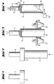
- the Blank is made free of play with a, from a main spindle of a pressure rolling device, not shown recorded, spinning roll mandrel 3 associated.
- the spinning roll mandrel 3 shown has, for example, a cylindrical outer contour and presses against the drilling direction against a face of the unprocessed base body 2.
- a counterforce By means of a counterforce, also not indicated, the insertion end in fixed in the axial direction and by a main drive of the spinning roller device in rotary motion added.
- Corresponding symbols that indicate a rotary movement are the Fig. 3 removable.
- Two pressure rollers 5, 6 of the pressure roller device have one in Drilling direction tapered outer contour. A takes place during the spinning rolling process Displacement of the rotating pressure rollers 5, 6 in the drilling direction. They reach along two axes not shown, pressure rollers 5, 6 locally on the circumference of the unprocessed carrier body 3 a. This reveals the Fig. 3.
- the pressure of the pressure rollers 5, 6 makes the material of the carrier body 2 plastic deformed and partly displaced in the drilling direction along the spinning roll mandrel 3, so that the carrier body 3 receives its tubular shape.
- the defined movement of the spinning rollers 5, 6 leads to the fact that the portion of the blank forming the carrier body 2 is applied to the required wall thickness is reduced and brought to the desired length.
- tubular support bodies 2 with a length can be produced manufacture from 20 mm to 500 mm.
- the wall thickness of the support body 2 increases towards the free end of the drilling direction Carrier body 2 towards, so that at least one diamond cutting element, not shown can be fixed well on the support body 2.
- the extension 8 of the support body 2 results from a radial expansion of the outer contour of the carrier body 2 and extends over a length measured parallel to the drilling direction, that of 0.04 to 0.14 times the total length of the carrier body 2 corresponds.
- the wall thickness of the carrier body 2 at the free end on the drilling direction is 1.5 mm to 3.5 mm.
- the bottom of the carrier body 2 can be bell-shaped.
- Fig. 5 shows a base body with a tubular support body 12 which is integral with an insertion end 11 is connected.
- the insertion end 11 has a closed Longitudinal groove 17 on.
- the outside and the inside are with one for example trapezoidal thread profiling.
Landscapes
- Engineering & Computer Science (AREA)
- Geology (AREA)
- Mechanical Engineering (AREA)
- Life Sciences & Earth Sciences (AREA)
- Mining & Mineral Resources (AREA)
- General Life Sciences & Earth Sciences (AREA)
- Fluid Mechanics (AREA)
- Environmental & Geological Engineering (AREA)
- Physics & Mathematics (AREA)
- Geochemistry & Mineralogy (AREA)
- Earth Drilling (AREA)
- Processing Of Stones Or Stones Resemblance Materials (AREA)
- Polishing Bodies And Polishing Tools (AREA)
- Carbon And Carbon Compounds (AREA)
- Shaping Metal By Deep-Drawing, Or The Like (AREA)
Abstract
Description
- Fig.1
- ein Rohteil aus dem der erfindungsgemässe Grundkörper fertigbar ist;
- Fig. 2
- das Rohteil gemäss Fig. 1 in Verbindung mit einem Drückwalzdorn;
- Fig. 3
- Herstellung des rohrförmigen Trägerkörpers aus einem Teil des Rohteiles gemäss Fig. 1 mit Hilfe mehrere Drückwalzen;
- Fig. 4
- spannabhebende Bearbeitung des Einsteckendes und des bohrrichtungsseitigen freien Endes des Trägerkörpers;
- Fig. 5
- ein weiterer erfindungsgemässer Grundkörper, dessen Trägerkörper an einer Innen- und Aussenseite mit einer Profilierung versehen ist.
Claims (7)
- Grundkörper für eine Diamantbohrkrone mit einem, einen Boden (4) aufweisenden, rohrförmigen Trägerkörper (2, 12) und einem vom Boden (4) abragenden Einsteckende (1, 11), dadurch gekennzeichnet, dass der Trägerkörper (2, 12) und der Boden (4) im Drückwalzverfahren hergestellt sind.
- Grundkörper nach Anspruch 1, dadurch gekennzeichnet, dass der Trägerkörper (2, 12) eine Wandstärke aufweist, die dem 0,008- bis 0,016-fachen Aussendurchmesser des Trägerkörpers (2, 12) entspricht.
- Grundkörper nach Anspruch 1 oder 2, dadurch gekennzeichnet, dass der Trägerkörper (2, 12) eine Rundlaufabweichung von weniger als 1,3 mm aufweist.
- Grundkörper nach einem der Ansprüche 1 bis 3, dadurch gekennzeichnet, dass der Trägerkörper (12) an der Aussenseite und/oder Innenseite mit einer Profilierung (13, 14) versehen ist.
- Grundkörper nach Anspruch 4, dadurch gekennzeichnet, dass die Profilierung (13, 14) spiralförmig ausgebildet ist.
- Grundkörper nach einem der Ansprüche 1 bis 5, dadurch gekennzeichnet, dass sich die Wandstärke des Trägerkörpers (2, 12) zum bohrrichtungsseitigen, freien Ende des Trägerkörpes (2, 12) hin erweitert.
- Grundkörper nach Anspruch 6, dadurch gekennzeichnet, dass sich die Erweiterung der Wandstärke über eine Länge erstreckt, die der 0,04- bis 0,14-fachen Gesamtlänge des Trägerkörpers (2, 12) entspricht.
Applications Claiming Priority (2)
| Application Number | Priority Date | Filing Date | Title |
|---|---|---|---|
| DE10041911 | 2000-08-25 | ||
| DE10041911A DE10041911B4 (de) | 2000-08-25 | 2000-08-25 | Diamantbohrkrone |
Publications (3)
| Publication Number | Publication Date |
|---|---|
| EP1182324A2 true EP1182324A2 (de) | 2002-02-27 |
| EP1182324A3 EP1182324A3 (de) | 2002-04-03 |
| EP1182324B1 EP1182324B1 (de) | 2005-05-11 |
Family
ID=7653838
Family Applications (1)
| Application Number | Title | Priority Date | Filing Date |
|---|---|---|---|
| EP01810780A Expired - Lifetime EP1182324B1 (de) | 2000-08-25 | 2001-08-13 | Diamantbohrkrone |
Country Status (6)
| Country | Link |
|---|---|
| US (1) | US6572447B2 (de) |
| EP (1) | EP1182324B1 (de) |
| JP (1) | JP5107491B2 (de) |
| AT (1) | ATE295469T1 (de) |
| DE (2) | DE10041911B4 (de) |
| DK (1) | DK1182324T3 (de) |
Cited By (2)
| Publication number | Priority date | Publication date | Assignee | Title |
|---|---|---|---|---|
| DE102023121703B3 (de) | 2023-08-14 | 2024-07-25 | Thyssenkrupp Steel Europe Ag | Verfahren zur Herstellung einer Bohrkrone |
| DE102023132107A1 (de) | 2023-11-17 | 2025-05-22 | Thyssenkrupp Steel Europe Ag | Verfahren zur Herstellung einer Bohrkrone sowie entsprechend hergestellte Bohrkrone |
Families Citing this family (4)
| Publication number | Priority date | Publication date | Assignee | Title |
|---|---|---|---|---|
| CN104675330A (zh) * | 2013-11-27 | 2015-06-03 | 中国石油化工股份有限公司 | 一种干法取芯钻头 |
| US10662716B2 (en) * | 2017-10-06 | 2020-05-26 | Kennametal Inc. | Thin-walled earth boring tools and methods of making the same |
| US11998987B2 (en) | 2017-12-05 | 2024-06-04 | Kennametal Inc. | Additive manufacturing techniques and applications thereof |
| WO2020198245A1 (en) | 2019-03-25 | 2020-10-01 | Kennametal Inc. | Additive manufacturing techniques and applications thereof |
Family Cites Families (13)
| Publication number | Priority date | Publication date | Assignee | Title |
|---|---|---|---|---|
| US3692127A (en) * | 1971-05-10 | 1972-09-19 | Walter R Hampe | Rotary diamond core bit |
| JPS537145B2 (de) * | 1974-01-18 | 1978-03-15 | ||
| DE2807198A1 (de) * | 1978-02-20 | 1979-08-30 | Heller Verwaltungsges | Verfahren zum herstellen einer bohrkrone und nach dem verfahren hergestellte bohrkrone |
| US4328647A (en) * | 1980-04-09 | 1982-05-11 | Brammall, Inc. | Inside, outside honing tool |
| DE3603499A1 (de) * | 1985-05-07 | 1986-11-13 | Geißler & Kuper GmbH Diamantwerkzeug - Wiederaufbereitung, 3100 Celle | Diamantbohrkrone mit schaftrohr und rohrgewindeanschluss |
| DE3744095A1 (de) * | 1987-12-24 | 1989-07-13 | Josef Dipl In Ehrenschwendtner | Verfahren zur herstellung von zylinderlaufbuechsen |
| JPH0746496Y2 (ja) * | 1988-03-03 | 1995-10-25 | 有限会社吉野精機 | 小孔穿孔用回転ドリル |
| DE8805449U1 (de) * | 1988-04-25 | 1988-06-09 | Maier, Wolfgang, 5630 Remscheid | Diamant-Kernbohrer |
| JP2515111Y2 (ja) * | 1990-09-01 | 1996-10-30 | ノリタケダイヤ株式会社 | ダイヤモンドドリル |
| KR100277320B1 (ko) * | 1992-06-03 | 2001-01-15 | 가나이 쓰도무 | 온라인 롤 연삭 장치를 구비한 압연기와 압연 방법 및 회전 숫돌 |
| US5910041A (en) * | 1997-03-06 | 1999-06-08 | Keltech Engineering | Lapping apparatus and process with raised edge on platen |
| US6108856A (en) * | 1997-10-09 | 2000-08-29 | The Malish Corporation | Molded pad driver |
| JPH11169985A (ja) * | 1997-12-04 | 1999-06-29 | Mazda Motor Corp | 歯付円筒部品の成形方法 |
-
2000
- 2000-08-25 DE DE10041911A patent/DE10041911B4/de not_active Expired - Lifetime
-
2001
- 2001-08-13 EP EP01810780A patent/EP1182324B1/de not_active Expired - Lifetime
- 2001-08-13 DK DK01810780T patent/DK1182324T3/da active
- 2001-08-13 DE DE50106178T patent/DE50106178D1/de not_active Expired - Fee Related
- 2001-08-13 AT AT01810780T patent/ATE295469T1/de active
- 2001-08-21 US US09/933,969 patent/US6572447B2/en not_active Expired - Lifetime
- 2001-08-22 JP JP2001251002A patent/JP5107491B2/ja not_active Expired - Fee Related
Cited By (2)
| Publication number | Priority date | Publication date | Assignee | Title |
|---|---|---|---|---|
| DE102023121703B3 (de) | 2023-08-14 | 2024-07-25 | Thyssenkrupp Steel Europe Ag | Verfahren zur Herstellung einer Bohrkrone |
| DE102023132107A1 (de) | 2023-11-17 | 2025-05-22 | Thyssenkrupp Steel Europe Ag | Verfahren zur Herstellung einer Bohrkrone sowie entsprechend hergestellte Bohrkrone |
Also Published As
| Publication number | Publication date |
|---|---|
| DE10041911B4 (de) | 2009-02-05 |
| EP1182324A3 (de) | 2002-04-03 |
| EP1182324B1 (de) | 2005-05-11 |
| US6572447B2 (en) | 2003-06-03 |
| DK1182324T3 (da) | 2005-09-12 |
| US20020023635A1 (en) | 2002-02-28 |
| DE50106178D1 (de) | 2005-06-16 |
| DE10041911A1 (de) | 2002-03-07 |
| ATE295469T1 (de) | 2005-05-15 |
| JP5107491B2 (ja) | 2012-12-26 |
| JP2002096133A (ja) | 2002-04-02 |
Similar Documents
| Publication | Publication Date | Title |
|---|---|---|
| DE102011075769A1 (de) | Bohrer und Herstellungsverfahren | |
| EP0844055B1 (de) | Hohlbohrwerkzeug mit einem aus zwei koaxial zueinander angeordneten miteinander verbunden Rohren gebildeten Trägerkörper | |
| EP0707129B1 (de) | Bohrwerkzeug mit Trägerkörper und Schneidkörpern | |
| DE3830814C2 (de) | ||
| EP3037229A1 (de) | Bohrring für eine Kernbohrkrone | |
| DE2735368C2 (de) | Gesteinsbohrkrone mit einem Hartmetall-Bohrkopf | |
| EP0600824B1 (de) | Verfahren zur Herstellung von Diamantbohrkronen | |
| EP0653544B1 (de) | Spiralbohrer | |
| EP0304702A1 (de) | Bohrer | |
| EP1182324B1 (de) | Diamantbohrkrone | |
| DE3413108A1 (de) | Ringlochschneider | |
| EP0748668B1 (de) | Verfahren zur Herstellung von Drehbohrwerkzeugen | |
| DE3821056A1 (de) | Bohrer zur herstellung von bohrloechern mit hinterschneidung | |
| DE3314718A1 (de) | Tiefbohrwerkzeug und verfahren zu seiner herstellung | |
| EP0170877B1 (de) | Offenend-Spinnrotor und Verfahren zu seiner Herstellung | |
| DE8221158U1 (de) | Bohrwerkzeug zum erzeugen von bohrloechern mit wenigstens einer erweiterung am bohrlochgrund | |
| DE10353283A1 (de) | Werkzeugaufnahme für einen Bohrhammer | |
| DE763225C (de) | Rollenlager | |
| DE3227767A1 (de) | Bohrwerkzeug zum erzeugen von bohrloechern mit wenigstens einer erweiterung am bohrlochgrund | |
| DE3015695A1 (de) | Bohrgestaenge fuer ein senkbohrwerkzeug | |
| EP1270121A2 (de) | Wälzfräser | |
| EP0541942A1 (de) | Bohrrohr | |
| DE69121575T2 (de) | Bohrstrangelement mit einer Nut von variabler Tiefe | |
| EP2463047B1 (de) | Hinterschneidwerkzeug | |
| DE2105219C3 (de) | Diamantbohrmeißel |
Legal Events
| Date | Code | Title | Description |
|---|---|---|---|
| PUAI | Public reference made under article 153(3) epc to a published international application that has entered the european phase |
Free format text: ORIGINAL CODE: 0009012 |
|
| PUAL | Search report despatched |
Free format text: ORIGINAL CODE: 0009013 |
|
| AK | Designated contracting states |
Kind code of ref document: A2 Designated state(s): AT BE CH CY DE DK ES FI FR GB GR IE IT LI LU MC NL PT SE TR |
|
| AX | Request for extension of the european patent |
Free format text: AL;LT;LV;MK;RO;SI |
|
| RIC1 | Information provided on ipc code assigned before grant |
Free format text: 7E 21B 10/48 A, 7E 21B 10/02 B |
|
| AK | Designated contracting states |
Kind code of ref document: A3 Designated state(s): AT BE CH CY DE DK ES FI FR GB GR IE IT LI LU MC NL PT SE TR |
|
| AX | Request for extension of the european patent |
Free format text: AL;LT;LV;MK;RO;SI |
|
| 17P | Request for examination filed |
Effective date: 20021004 |
|
| AKX | Designation fees paid |
Free format text: AT BE CH CY DE DK ES FI FR GB GR IE IT LI LU MC NL PT SE TR |
|
| GRAP | Despatch of communication of intention to grant a patent |
Free format text: ORIGINAL CODE: EPIDOSNIGR1 |
|
| GRAS | Grant fee paid |
Free format text: ORIGINAL CODE: EPIDOSNIGR3 |
|
| GRAA | (expected) grant |
Free format text: ORIGINAL CODE: 0009210 |
|
| AK | Designated contracting states |
Kind code of ref document: B1 Designated state(s): AT BE CH CY DE DK ES FI FR GB GR IE IT LI LU MC NL PT SE TR |
|
| PG25 | Lapsed in a contracting state [announced via postgrant information from national office to epo] |
Ref country code: IT Free format text: LAPSE BECAUSE OF FAILURE TO SUBMIT A TRANSLATION OF THE DESCRIPTION OR TO PAY THE FEE WITHIN THE PRESCRIBED TIME-LIMIT;WARNING: LAPSES OF ITALIAN PATENTS WITH EFFECTIVE DATE BEFORE 2007 MAY HAVE OCCURRED AT ANY TIME BEFORE 2007. THE CORRECT EFFECTIVE DATE MAY BE DIFFERENT FROM THE ONE RECORDED. Effective date: 20050511 Ref country code: TR Free format text: LAPSE BECAUSE OF FAILURE TO SUBMIT A TRANSLATION OF THE DESCRIPTION OR TO PAY THE FEE WITHIN THE PRESCRIBED TIME-LIMIT Effective date: 20050511 Ref country code: FI Free format text: LAPSE BECAUSE OF FAILURE TO SUBMIT A TRANSLATION OF THE DESCRIPTION OR TO PAY THE FEE WITHIN THE PRESCRIBED TIME-LIMIT Effective date: 20050511 Ref country code: IE Free format text: LAPSE BECAUSE OF FAILURE TO SUBMIT A TRANSLATION OF THE DESCRIPTION OR TO PAY THE FEE WITHIN THE PRESCRIBED TIME-LIMIT Effective date: 20050511 |
|
| REG | Reference to a national code |
Ref country code: GB Ref legal event code: FG4D Free format text: NOT ENGLISH |
|
| REG | Reference to a national code |
Ref country code: CH Ref legal event code: EP |
|
| REG | Reference to a national code |
Ref country code: SE Ref legal event code: TRGR |
|
| REG | Reference to a national code |
Ref country code: IE Ref legal event code: FG4D Free format text: LANGUAGE OF EP DOCUMENT: GERMAN |
|
| REF | Corresponds to: |
Ref document number: 50106178 Country of ref document: DE Date of ref document: 20050616 Kind code of ref document: P |
|
| GBT | Gb: translation of ep patent filed (gb section 77(6)(a)/1977) |
Effective date: 20050617 |
|
| PG25 | Lapsed in a contracting state [announced via postgrant information from national office to epo] |
Ref country code: GR Free format text: LAPSE BECAUSE OF FAILURE TO SUBMIT A TRANSLATION OF THE DESCRIPTION OR TO PAY THE FEE WITHIN THE PRESCRIBED TIME-LIMIT Effective date: 20050811 |
|
| PG25 | Lapsed in a contracting state [announced via postgrant information from national office to epo] |
Ref country code: CY Free format text: LAPSE BECAUSE OF FAILURE TO SUBMIT A TRANSLATION OF THE DESCRIPTION OR TO PAY THE FEE WITHIN THE PRESCRIBED TIME-LIMIT Effective date: 20050813 Ref country code: LU Free format text: LAPSE BECAUSE OF NON-PAYMENT OF DUE FEES Effective date: 20050813 |
|
| PG25 | Lapsed in a contracting state [announced via postgrant information from national office to epo] |
Ref country code: ES Free format text: LAPSE BECAUSE OF FAILURE TO SUBMIT A TRANSLATION OF THE DESCRIPTION OR TO PAY THE FEE WITHIN THE PRESCRIBED TIME-LIMIT Effective date: 20050822 |
|
| PG25 | Lapsed in a contracting state [announced via postgrant information from national office to epo] |
Ref country code: MC Free format text: LAPSE BECAUSE OF NON-PAYMENT OF DUE FEES Effective date: 20050831 |
|
| REG | Reference to a national code |
Ref country code: DK Ref legal event code: T3 |
|
| PG25 | Lapsed in a contracting state [announced via postgrant information from national office to epo] |
Ref country code: PT Free format text: LAPSE BECAUSE OF FAILURE TO SUBMIT A TRANSLATION OF THE DESCRIPTION OR TO PAY THE FEE WITHIN THE PRESCRIBED TIME-LIMIT Effective date: 20051019 |
|
| REG | Reference to a national code |
Ref country code: IE Ref legal event code: FD4D |
|
| PG25 | Lapsed in a contracting state [announced via postgrant information from national office to epo] |
Ref country code: DE Free format text: LAPSE BECAUSE OF NON-PAYMENT OF DUE FEES Effective date: 20060301 |
|
| PLBE | No opposition filed within time limit |
Free format text: ORIGINAL CODE: 0009261 |
|
| STAA | Information on the status of an ep patent application or granted ep patent |
Free format text: STATUS: NO OPPOSITION FILED WITHIN TIME LIMIT |
|
| ET | Fr: translation filed | ||
| 26N | No opposition filed |
Effective date: 20060214 |
|
| REG | Reference to a national code |
Ref country code: FR Ref legal event code: PLFP Year of fee payment: 16 |
|
| REG | Reference to a national code |
Ref country code: FR Ref legal event code: PLFP Year of fee payment: 17 |
|
| REG | Reference to a national code |
Ref country code: FR Ref legal event code: PLFP Year of fee payment: 18 |
|
| PGFP | Annual fee paid to national office [announced via postgrant information from national office to epo] |
Ref country code: NL Payment date: 20190821 Year of fee payment: 19 |
|
| PGFP | Annual fee paid to national office [announced via postgrant information from national office to epo] |
Ref country code: DK Payment date: 20190821 Year of fee payment: 19 Ref country code: FR Payment date: 20190822 Year of fee payment: 19 Ref country code: SE Payment date: 20190821 Year of fee payment: 19 |
|
| PGFP | Annual fee paid to national office [announced via postgrant information from national office to epo] |
Ref country code: BE Payment date: 20190821 Year of fee payment: 19 |
|
| PGFP | Annual fee paid to national office [announced via postgrant information from national office to epo] |
Ref country code: AT Payment date: 20190822 Year of fee payment: 19 Ref country code: GB Payment date: 20190821 Year of fee payment: 19 |
|
| PGFP | Annual fee paid to national office [announced via postgrant information from national office to epo] |
Ref country code: CH Payment date: 20190821 Year of fee payment: 19 |
|
| REG | Reference to a national code |
Ref country code: DK Ref legal event code: EBP Effective date: 20200831 |
|
| REG | Reference to a national code |
Ref country code: SE Ref legal event code: EUG |
|
| REG | Reference to a national code |
Ref country code: CH Ref legal event code: PL |
|
| REG | Reference to a national code |
Ref country code: NL Ref legal event code: MM Effective date: 20200901 |
|
| REG | Reference to a national code |
Ref country code: AT Ref legal event code: MM01 Ref document number: 295469 Country of ref document: AT Kind code of ref document: T Effective date: 20200813 |
|
| GBPC | Gb: european patent ceased through non-payment of renewal fee |
Effective date: 20200813 |
|
| PG25 | Lapsed in a contracting state [announced via postgrant information from national office to epo] |
Ref country code: LI Free format text: LAPSE BECAUSE OF NON-PAYMENT OF DUE FEES Effective date: 20200831 Ref country code: CH Free format text: LAPSE BECAUSE OF NON-PAYMENT OF DUE FEES Effective date: 20200831 |
|
| REG | Reference to a national code |
Ref country code: BE Ref legal event code: MM Effective date: 20200831 |
|
| PG25 | Lapsed in a contracting state [announced via postgrant information from national office to epo] |
Ref country code: AT Free format text: LAPSE BECAUSE OF NON-PAYMENT OF DUE FEES Effective date: 20200813 Ref country code: SE Free format text: LAPSE BECAUSE OF NON-PAYMENT OF DUE FEES Effective date: 20200814 |
|
| PG25 | Lapsed in a contracting state [announced via postgrant information from national office to epo] |
Ref country code: FR Free format text: LAPSE BECAUSE OF NON-PAYMENT OF DUE FEES Effective date: 20200831 |
|
| PG25 | Lapsed in a contracting state [announced via postgrant information from national office to epo] |
Ref country code: DK Free format text: LAPSE BECAUSE OF NON-PAYMENT OF DUE FEES Effective date: 20200831 Ref country code: BE Free format text: LAPSE BECAUSE OF NON-PAYMENT OF DUE FEES Effective date: 20200831 Ref country code: GB Free format text: LAPSE BECAUSE OF NON-PAYMENT OF DUE FEES Effective date: 20200813 |
|
| PG25 | Lapsed in a contracting state [announced via postgrant information from national office to epo] |
Ref country code: NL Free format text: LAPSE BECAUSE OF NON-PAYMENT OF DUE FEES Effective date: 20200901 |