EP1180602A1 - Steuerventileinrichtung sowie als Bestandteil derselben geeignetes Ventil - Google Patents
Steuerventileinrichtung sowie als Bestandteil derselben geeignetes Ventil Download PDFInfo
- Publication number
- EP1180602A1 EP1180602A1 EP20000117006 EP00117006A EP1180602A1 EP 1180602 A1 EP1180602 A1 EP 1180602A1 EP 20000117006 EP20000117006 EP 20000117006 EP 00117006 A EP00117006 A EP 00117006A EP 1180602 A1 EP1180602 A1 EP 1180602A1
- Authority
- EP
- European Patent Office
- Prior art keywords
- valve
- electrical
- control device
- connection
- contact means
- Prior art date
- Legal status (The legal status is an assumption and is not a legal conclusion. Google has not performed a legal analysis and makes no representation as to the accuracy of the status listed.)
- Granted
Links
- 239000012530 fluid Substances 0.000 claims abstract description 21
- 238000005516 engineering process Methods 0.000 claims description 5
- 238000013461 design Methods 0.000 description 6
- 238000003780 insertion Methods 0.000 description 3
- 230000037431 insertion Effects 0.000 description 3
- 230000000295 complement effect Effects 0.000 description 2
- 238000006243 chemical reaction Methods 0.000 description 1
- 238000004140 cleaning Methods 0.000 description 1
- 238000010276 construction Methods 0.000 description 1
- 238000011161 development Methods 0.000 description 1
- 230000018109 developmental process Effects 0.000 description 1
- 238000000034 method Methods 0.000 description 1
- 238000012986 modification Methods 0.000 description 1
- 230000004048 modification Effects 0.000 description 1
Images

Classifications
-
- F—MECHANICAL ENGINEERING; LIGHTING; HEATING; WEAPONS; BLASTING
- F15—FLUID-PRESSURE ACTUATORS; HYDRAULICS OR PNEUMATICS IN GENERAL
- F15B—SYSTEMS ACTING BY MEANS OF FLUIDS IN GENERAL; FLUID-PRESSURE ACTUATORS, e.g. SERVOMOTORS; DETAILS OF FLUID-PRESSURE SYSTEMS, NOT OTHERWISE PROVIDED FOR
- F15B13/00—Details of servomotor systems ; Valves for servomotor systems
- F15B13/02—Fluid distribution or supply devices characterised by their adaptation to the control of servomotors
- F15B13/06—Fluid distribution or supply devices characterised by their adaptation to the control of servomotors for use with two or more servomotors
- F15B13/08—Assemblies of units, each for the control of a single servomotor only
- F15B13/0803—Modular units
- F15B13/0846—Electrical details
- F15B13/0857—Electrical connecting means, e.g. plugs, sockets
-
- F—MECHANICAL ENGINEERING; LIGHTING; HEATING; WEAPONS; BLASTING
- F15—FLUID-PRESSURE ACTUATORS; HYDRAULICS OR PNEUMATICS IN GENERAL
- F15B—SYSTEMS ACTING BY MEANS OF FLUIDS IN GENERAL; FLUID-PRESSURE ACTUATORS, e.g. SERVOMOTORS; DETAILS OF FLUID-PRESSURE SYSTEMS, NOT OTHERWISE PROVIDED FOR
- F15B13/00—Details of servomotor systems ; Valves for servomotor systems
- F15B13/02—Fluid distribution or supply devices characterised by their adaptation to the control of servomotors
- F15B13/06—Fluid distribution or supply devices characterised by their adaptation to the control of servomotors for use with two or more servomotors
- F15B13/08—Assemblies of units, each for the control of a single servomotor only
- F15B13/0803—Modular units
- F15B13/0807—Manifolds
- F15B13/0814—Monoblock manifolds
-
- F—MECHANICAL ENGINEERING; LIGHTING; HEATING; WEAPONS; BLASTING
- F15—FLUID-PRESSURE ACTUATORS; HYDRAULICS OR PNEUMATICS IN GENERAL
- F15B—SYSTEMS ACTING BY MEANS OF FLUIDS IN GENERAL; FLUID-PRESSURE ACTUATORS, e.g. SERVOMOTORS; DETAILS OF FLUID-PRESSURE SYSTEMS, NOT OTHERWISE PROVIDED FOR
- F15B13/00—Details of servomotor systems ; Valves for servomotor systems
- F15B13/02—Fluid distribution or supply devices characterised by their adaptation to the control of servomotors
- F15B13/06—Fluid distribution or supply devices characterised by their adaptation to the control of servomotors for use with two or more servomotors
- F15B13/08—Assemblies of units, each for the control of a single servomotor only
- F15B13/0803—Modular units
- F15B13/0832—Modular valves
- F15B13/0835—Cartridge type valves
-
- F—MECHANICAL ENGINEERING; LIGHTING; HEATING; WEAPONS; BLASTING
- F15—FLUID-PRESSURE ACTUATORS; HYDRAULICS OR PNEUMATICS IN GENERAL
- F15B—SYSTEMS ACTING BY MEANS OF FLUIDS IN GENERAL; FLUID-PRESSURE ACTUATORS, e.g. SERVOMOTORS; DETAILS OF FLUID-PRESSURE SYSTEMS, NOT OTHERWISE PROVIDED FOR
- F15B13/00—Details of servomotor systems ; Valves for servomotor systems
- F15B13/02—Fluid distribution or supply devices characterised by their adaptation to the control of servomotors
- F15B13/06—Fluid distribution or supply devices characterised by their adaptation to the control of servomotors for use with two or more servomotors
- F15B13/08—Assemblies of units, each for the control of a single servomotor only
- F15B13/0803—Modular units
- F15B13/0846—Electrical details
- F15B13/0867—Data bus systems
-
- F—MECHANICAL ENGINEERING; LIGHTING; HEATING; WEAPONS; BLASTING
- F15—FLUID-PRESSURE ACTUATORS; HYDRAULICS OR PNEUMATICS IN GENERAL
- F15B—SYSTEMS ACTING BY MEANS OF FLUIDS IN GENERAL; FLUID-PRESSURE ACTUATORS, e.g. SERVOMOTORS; DETAILS OF FLUID-PRESSURE SYSTEMS, NOT OTHERWISE PROVIDED FOR
- F15B13/00—Details of servomotor systems ; Valves for servomotor systems
- F15B13/02—Fluid distribution or supply devices characterised by their adaptation to the control of servomotors
- F15B13/06—Fluid distribution or supply devices characterised by their adaptation to the control of servomotors for use with two or more servomotors
- F15B13/08—Assemblies of units, each for the control of a single servomotor only
- F15B13/0803—Modular units
- F15B13/0875—Channels for electrical components, e.g. for cables or sensors
-
- F—MECHANICAL ENGINEERING; LIGHTING; HEATING; WEAPONS; BLASTING
- F15—FLUID-PRESSURE ACTUATORS; HYDRAULICS OR PNEUMATICS IN GENERAL
- F15B—SYSTEMS ACTING BY MEANS OF FLUIDS IN GENERAL; FLUID-PRESSURE ACTUATORS, e.g. SERVOMOTORS; DETAILS OF FLUID-PRESSURE SYSTEMS, NOT OTHERWISE PROVIDED FOR
- F15B13/00—Details of servomotor systems ; Valves for servomotor systems
- F15B13/02—Fluid distribution or supply devices characterised by their adaptation to the control of servomotors
- F15B13/06—Fluid distribution or supply devices characterised by their adaptation to the control of servomotors for use with two or more servomotors
- F15B13/08—Assemblies of units, each for the control of a single servomotor only
- F15B13/0803—Modular units
- F15B13/0878—Assembly of modular units
- F15B13/0885—Assembly of modular units using valves combined with other components
- F15B13/0889—Valves combined with electrical components
-
- F—MECHANICAL ENGINEERING; LIGHTING; HEATING; WEAPONS; BLASTING
- F15—FLUID-PRESSURE ACTUATORS; HYDRAULICS OR PNEUMATICS IN GENERAL
- F15B—SYSTEMS ACTING BY MEANS OF FLUIDS IN GENERAL; FLUID-PRESSURE ACTUATORS, e.g. SERVOMOTORS; DETAILS OF FLUID-PRESSURE SYSTEMS, NOT OTHERWISE PROVIDED FOR
- F15B21/00—Common features of fluid actuator systems; Fluid-pressure actuator systems or details thereof, not covered by any other group of this subclass
- F15B21/08—Servomotor systems incorporating electrically operated control means
-
- Y—GENERAL TAGGING OF NEW TECHNOLOGICAL DEVELOPMENTS; GENERAL TAGGING OF CROSS-SECTIONAL TECHNOLOGIES SPANNING OVER SEVERAL SECTIONS OF THE IPC; TECHNICAL SUBJECTS COVERED BY FORMER USPC CROSS-REFERENCE ART COLLECTIONS [XRACs] AND DIGESTS
- Y10—TECHNICAL SUBJECTS COVERED BY FORMER USPC
- Y10T—TECHNICAL SUBJECTS COVERED BY FORMER US CLASSIFICATION
- Y10T137/00—Fluid handling
- Y10T137/8376—Combined
Definitions
- the invention first relates to a control device with one a bus connection, electronics and at least one electronic control unit with electrical output, the electrical output being one over first electrical plug contact means and first mechanical fastening means having assigned first connection device is that for electrical contact and at the same time mechanical Fixing a connection component that serves a detachable interacting with the first connection device second connection device with second electrical plug contact means and second mechanical fasteners having.
- the invention further relates to an electrically activatable one Valve, which is designed in particular in Used in connection with such a control device to become.
- a control device of the type mentioned above is used, for example in the article " Kompaktmodule K45, digital ", 1999.
- the control device includes a control unit called a compact module, the a bus connection, electronics and at least one or has several electrical outputs.
- the electrical outputs the first connection devices are assigned that Allow connection components with which the connection to an actuator to be controlled electrically, for example a relay that can be manufactured. In doing so, the electrical outputs a plug-type connection component connected via a cable to the actuator to be controlled communicates.
- the one at the respective electrical output provided electrical plug contact means via five-way plug contacts, their assignment according to the respective control purpose is selected.
- the electronic control device supplied via a fieldbus with signals that evaluated in integrated electronics and assigned correctly be connected to the existing outputs.
- the known control device is a control device product designed for electrotechnical components.
- the sector of purely electrical control tasks Automation technology also from combines electro-fluidic and above all electro-pneumatic Control tasks mastered.
- So far special control devices have come regularly used both via an electronic control unit as well as a plurality of battery-like lined up valves have, the valves on a fluid distribution plate be attached and at the same time over from the attachment measures independent electrical plug contact means with the electronic control unit.
- Such a control device works, for example from EP 0 629 783 B1.
- control device known from EP 0 629 783 B1 contains several electrical outputs for control electrotechnical components, for example in the form valve actuators. Your use is limited however, the connection of electrical lines, that lead to externally placed valve actuators. As soon as the valves are designed as part of the control device the usual contact is made using the valve-specific plug contact means.
- the invention therefore has set itself the goal of a control device to create it, which is also predominantly electric and electronically orient users towards cost-effective Way enables fluid power valves in the controller included.
- Another goal is an electric propose activatable valve that is special good for use in connection with electronic control units suitable.
- connection component directly from an electrical activatable valve is formed, which is exclusively about the cooperating connection devices electrically contacted and held mechanically.
- the second goal is achieved using a electrically activated valve, one for direct Connection to one with a first electrical connection device provided electrical output of an electronic Control unit provided second connection device has, the second connection device via second has electrical plug-in contact means that are connected to the electrical Output connected state with first electrical Interact plug contact means of the first connection device, the second electrical provided on the valve Plug contact means are designed so that they are a direct electrical contact with the first electrical Allow plug contact means of the control device, the via plug contacts distributed in the manner of a cube five features.
- the control device enables direct Connection of one used to control fluid flows Valve to the electrical output of the electronic Control unit. Because of the cooperating with each other Connection devices not only the electrical contact takes place, but also the mechanical attachment takes place, a commercially available electronic Control unit comparable to that of the aforementioned Type equipped with a valve without mechanical conversions become. It is only the electrical assignment of the existing one adapt electrical plug contact means as required, which is completely problem-free and for example under Use of the existing electronics can take place.
- the second connection device provided on the valve is located expediently on an electrically activatable Valve actuator, which acts as a carrier for him to be actuated valve device of the valve takes over.
- the whole valve is therefore exclusively via the valve drive or the one provided on this and in particular in the valve drive integrated second connection device electrically and mechanically connected to the control unit.
- valve has an elongated shape
- recommends the second connection device is placed on a Face of the valve. This can be achieved in that the valve in the assembled state with the main expansion level the vertical longitudinal axis control unit is installed, what an optimal use of the footprint of the electronic Control unit enables.
- the cooperating electrical plug contact means are expediently designed as a plug and socket.
- the socket is preferably located on the electronic Control unit while the plug is placed on the valve.
- valve expediently only via fluid line connections for connecting fluid lines leading away so that individual cable routing is possible. All fluid line connections on the are preferred second connection device facing away from the valve provided so that there is no space for outgoing fluid lines is required.
- the control unit can have several electrical outputs, which are fully or partially equipped with valves. Possible is especially a mixed assembly on the one hand with valves and on the other hand with plug-like connection components, the via connected electrical cables to other electrotechnical or electronic components to lead.
- the control device can also with electrical inputs to be equipped with any signals, for example to be able to feed sensor signals.
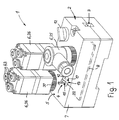
- Figure 1 shows a control not shown Consumer suitable control device 1, depending on Equipped as purely electronic, as purely electrofluidic or as a combination of the aforementioned functions Control device can be used.
- the embodiment shows a design designed for combined operation.
- the control device 1 has an electronic control unit 2, which expediently no fluid technology Contains components. It has a schematically indicated Bus connection 3, which is used to connect a field bus is suitable, via the between the electronic control unit 2 and a higher-level control and / or another electronic control units, preferably serial data exchange can take place.
- the fieldbus can in particular be a so-called ASI bus.
- the electronic control unit 2 contains at least one and preferably several electrical outputs 4, the outside are accessible and on which for operation electrically Actuators that can be activated require control signals and / or actuation energy can be tapped.
- electrical outputs are an exemplary embodiment 4 available, which are spaced together one and the same pad 5 of the electronic control unit 2 are assigned, but only one electrical Exit 4 is visible.
- the other electrical outputs 4 are covered by connection components 6, which on the respective electrical output 4 releasably connected are.
- the electronic control unit 2 has a plate-like one Shape, the pad 5 being one of the two larger outer surfaces is formed. With the orientation shown has the connection surface 5 vertically upwards.
- the electronic control unit 5 has a box-like one, for example Housing 7, in which an only indicated electronics 8 is housed. On the one hand, this communicates with the Bus connection 3 and the other with the electrical outputs 4 and in particular has the task that in the bus connection 3 electrical control signals fed in correctly to distribute on the existing electrical outputs 4.
- a in the exemplary embodiment by a closure body 12 covered access allows mechanical, depending on the design and / or electronic intervention on the electronics 8 of the control unit 2, for example addressing and assignment of the electrical outputs 4 to vary.
- the existing electrical outputs 4 are constructive identically trained.
- Each electrical output is 4 a first connection device 13 is assigned, which via the first electrical plug contact means 15 and first mechanical Fastening means 17 has. These funds are immediate arranged adjacent to each other and on the area of the respective electrical output 4 concentrated.
- the first connection device 13 and in particular the first one electrical plug contact means 15 preferably have one standardized structure. This corresponds to the exemplary embodiment the German industry standard DIN EN 60947-5-2. Accordingly contain the first electrical plug contact means 15 in total five first plug contacts 19, the distribution of which is usually the number "five" on cubes. Accordingly, four first plug contacts 19 are on the Corner points of a square and a fifth first plug contact 19 is in the center of the square.
- the first plug contact means 15 are preferably as shown designed as a socket, the first plug contacts 19th have the shape of elongated channel-like depressions and together to an outwardly facing end face of an associated Open out socket body 22.
- the first plug contacts 19 are in a manner not shown with the integrated Electronics 8 contacted.
- the socket body 22 protrudes from the interior of the housing 7 through a housing opening 23 out through, with its end face can protrude a little way beyond the connection surface 5.
- the first mechanical fasteners 17 contain a provided on the inner circumference of the housing opening 23 Internal thread 21.
- the first plug contacts 19 are usually assigned in such a way that two diagonally opposite plug contacts one Power supply of 24 volts (occupancy number 1) or 0 Volt (mass; occupancy number 3). The two others, diametrically opposite first plug contacts 19 (occupancy numbers 2 and 4) are data outputs.
- the central one Plug contact (assignment number 5) represents the grounding.
- connection component 6 Possible, the example in Figure 1 is indicated. From this connector 25 leads an electrical cable, not shown, to the controlled consumers. A different assignment chooses However, you should do this regularly if it is a connection component 6 is a valve 26, since then the control-technical peculiarities and in particular simplifications Is taken into account.
- each valve 26 has a releasably cooperating with the first connection device 13 second connection device 14, for cooperation provided with the first electrical plug contact means 15 second electrical plug contact means 16 and for cooperation with the first mechanical fastening means 17 serving second mechanical fastener 18 includes.
- Each valve is simply connected to the electronic one Control unit 2 connected with the second Connection device 14 ahead of the first connection device 13 is set, the first and second electrical Plug contact means 15, 16 in a double arrow indicated insertion direction 27 come into engagement and with the interlocking mechanical fasteners 17, 18 a firm mechanical fixation between the valve 26 and the electronic control unit 2.
- the mechanical fastening means 17, 18 can the mechanical fastening intervention automatically when Attachment of the valve 26 take place or an additional require active actuation. In the embodiment the latter is the case.
- the valve 26 is in the connected state solely by the two together cooperating first and second connection devices 13, 14 both electrically contacted and held mechanically. Additional contacting or fastening means are neither intended nor required.
- a major advantage is that you can connect a valve 26 only one to the electrical Output 4 existing first connection device 13 adapted second connection device 14 on the valve 26 is required. No other measures are necessary.
- the valve can thus existing and original for purely electronic without modifications Control tasks of imaginary electronic control units 2 be connected.
- the valve 26 also has a valve device 28 known, arbitrary structure, the details of which in Drawing are not shown. Inside the case of the Valve device 28 is a valve member that is different Switch position can assume a fluid flow to control.
- the switching position of the valve member is by an electrically activatable valve drive 32 of the Valve 26 specified that in the embodiment to the Valve device 28 is attached.
- the valve drive 32 it is for example an electromagnet or a piezoelectric actuator.
- the second connection device is expediently located 14 directly on the valve drive 32, at least partially executed as an integral part of the same can be. Accordingly, it results in the connected state the valves 26 a state in which the valve drive 32 as the sole carrier for the associated valve device 28 acts.
- the valve 26 has an elongated shape as shown the second connection device 14 and preferably also the valve drive 32 on a first end face 33 of the two end faces of the valve 26.
- the arrangement is there in particular so that the insertion direction 27 with the longitudinal axis 35 of the valve 26 coincides so that the Longitudinal axis of the assembled valve perpendicular to the main plane of expansion of the electronic control unit 2, which runs in the exemplary embodiment parallel to the connecting surface 5 is aligned. This way, on the pad 5 several connection components 6 in a compact arrangement placed side by side.
- second electrical plug contact means 16 in the embodiment, a connector that a plurality of pin-like, extending parallel to the direction of insertion 27 has second plug contacts 20.
- These second plug contacts 20 are of a sleeve 35 which is coaxial to the longitudinal axis 36 surround, on which, again coaxially, a screw 37 freely rotatable and at the same time essentially immovable axially is held.
- the screw member 37 has one for free End of the sleeve 36 extending annular portion 39, which is provided with an external thread 38. The latter is complementary to the internal thread 21 of the first mechanical Fastening means 17 formed.
- the sleeve 36 is on the Socket body 22 plugged in, at the same time the pin-like second plug contacts 20 in the channel-like first plug contacts 19 intervene. It becomes a mechanical fixation Screw part 37 manually rotated about the longitudinal axis 35 so that the threads of the two mechanical fasteners 17, 18 engage and the valve 26 against the outer surface 5 of the electronic control unit 2 is used.
- the Screw part 37 can be clamped to the housing 7, so that the valve 26 is held securely.
- the number of second plug contacts 20 depends on the Functionality of the valve drive to be supplied by them electrically 32. If the valve drive 32 with low voltage, operated with 24 volts, for example, two second ones are sufficient Plug contacts 20, which in the connected state with the first Plug contacts 19 of the occupancy numbers "1" and "3" in Get plug contact. An electrical assignment of the rest three first plug contacts 19 are unnecessary.
- Valve drives 32 are used which have a higher operating voltage need, for example in the order of magnitude of 110 volts or 230 volts, can be shown between the two second plug contacts 20 a central second Plug contact are provided for contacting the central first plug contact 20 is used to ground. This construction variant is not shown in the drawing.
- Valve 26 Between the electronic control unit 2 and a respective one Valve 26 is only in the connected state mechanical and electrical connections before, while fluidic Connections or interfaces are not available.
- connection devices 13, 14 equipped with positioning means 42 that the plugging process enable only in a very specific angle of rotation.
- positioning means 42 exist in the exemplary embodiment from one provided on the outer periphery of the socket body 32 Longitudinal groove and a complementary, preferably rib-like Projection on the inner surface of the sleeve 36.
- the fluid flows to be controlled by the valve device 28 are supplied and discharged via fluid lines that are connected to the valve 26 provided fluid line connections 43 releasably connected can be.
- the fluid line connections 43 can be designed as a plug connection means.
- all of the fluid line connections 43 on the opposite of the second connection device 14 Side of the valve 26 are provided in the embodiment that is, on the opposite of the first end face 33 second end face 34.
- the radially outside of the longitudinal axis 35 lying circumferential area of the valve 26 thus remains complete free of any follow-up measures, what the assembly of a electronic control unit 2 with valves 26 even then allowed if their electrical outputs 4 with little Are placed next to each other.
Landscapes
- Engineering & Computer Science (AREA)
- Physics & Mathematics (AREA)
- Fluid Mechanics (AREA)
- Mechanical Engineering (AREA)
- General Engineering & Computer Science (AREA)
- Analytical Chemistry (AREA)
- Chemical & Material Sciences (AREA)
- Valve Housings (AREA)
- Magnetically Actuated Valves (AREA)
- Electrically Driven Valve-Operating Means (AREA)
- Multi-Conductor Connections (AREA)
- Superconductors And Manufacturing Methods Therefor (AREA)
- Fluid-Driven Valves (AREA)
- Details Of Connecting Devices For Male And Female Coupling (AREA)
Abstract
Description
- Figur 1
- eine erste Bauform der erfindungsgemäßen Steuereinrichtung, die mit erfindungsgemäßen Ventilen einer ebenfalls bevorzugten Bauform ausgestattet ist,
- Figur 2
- eine Teildarstellung der Steuereinrichtung aus Figur 1, wobei ein teilweise aufgebrochenes Ventil im Moment vor der Steckmontage an einem elektrischen Ausgang der elektronischen Steuereinheit gezeigt ist, und
- Figur 3
- eine Stirnansicht des Ventils aus Figur 2 mit Blick gemäß Pfeil III auf die an dem Ventil vorgesehene zweite Anschlusseinrichtung.
Claims (16)
- Steuereinrichtung, mit einer einen Busanschluss (3), eine Elektronik (8) und mindestens einen elektrischen Ausgang (4) aufweisenden elektronischen Steuereinheit (2), wobei dem elektrischen Ausgang (4) eine über erste elektrische Steckkontaktmittel (15) und erste mechanische Befestigungsmittel (17) verfügende erste Anschlusseinrichtung (13) zugeordnet ist, die zum elektrischen Kontaktieren und zugleich mechanischen Fixieren einer Anschlusskomponente (6) dient, die eine lösbar mit der ersten Anschlusseinrichtung (13) zusammenwirkende zweite Anschlusseinrichtung (14) mit zweiten elektrischen Steckkontaktmitteln (16) und zweiten mechanischen Befestigungsmitteln (18) aufweist, dadurch gekennzeichnet, daß die Anschlusskomponente (6) unmittelbar von einem elektrisch aktivierbaren Ventil (26) gebildet ist, das ausschließlich über die miteinander kooperierenden Anschlusseinrichtungen (13, 14) elektrisch kontaktiert und mechanisch gehalten ist.
- Steuereinrichtung nach Anspruch 1, dadurch gekennzeichnet, daß die zweite Anschlusseinrichtung (14) an einem elektrisch aktivierbaren Ventilantrieb (32) des Ventils (26) vorgesehen ist, der als alleiniger Träger für die Ventileinrichtung (28) des Ventils (26) fungiert.
- Steuereinrichtung nach Anspruch 1 oder 2, dadurch gekennzeichnet, daß das Ventil (26) eine längliche Gestalt hat, wobei sich die zweite Anschlusseinrichtung (14) an einer Stirnseite (33) des Ventils (26) befindet.
- Steuereinrichtung nach Anspruch 3, dadurch gekennzeichnet, daß die Längsachse (35) des Ventils (26) senkrecht zur Hauptausdehnungsebene der Steuereinheit (2) verläuft.
- Steuereinrichtung nach einem der Ansprüche 1 bis 4, dadurch gekennzeichnet, daß die Steuereinheit (2) plattenartige Gestalt hat, wobei der mindestens eine elektrische Ausgang (4) an einer der beiden größeren Außenflächen vorgesehen ist.
- Steuereinrichtung nach einem der Ansprüche 1 bis 5, dadurch gekennzeichnet, daß die einen elektrischen Steckkontaktmittel (15) als Stecker und die anderen elektrischen Steckkontaktmittel (15) als Buchse ausgeführt sind.
- Steuereinrichtung nach einem der Ansprüche 1 bis 6, dadurch gekennzeichnet, daß die ersten elektrischen Steckkontaktmittel (15) über nach Art einer Würfel-Fünf verteilt angeordnete erste Steckkontakte (19) verfügen, wobei die zweiten elektrischen Steckkontaktmittel (16) wenigstens zwei zweite Steckkontakte (20) aufweisen, die so ausgebildet sind, daß sie mit ersten Steckkontakten (19) der ersten Steckkontaktmittel (15) elektrisch kontaktierbar sind.
- Steuereinrichtung nach Anspruch 7, dadurch gekennzeichnet, daß das Steckkontaktbild der ersten Steckkontakte (19) der Norm DIN EN 60947-5-2 entspricht.
- Steuereinrichtung nach einem der Ansprüche 1 bis 8, dadurch gekennzeichnet, daß an dem Ventil (26) Fluidleitungsanschlüsse (43) zum Anschließen von wegführenden Fluidleitungen vorgesehen sind.
- Steuereinrichtung nach Anspruch 9, dadurch gekennzeichnet, daß sämtliche Fluidleitungsanschlüsse (43) auf der der zweiten Anschlusseinrichtung (14) entgegengesetzten Seite des Ventils (26) vorgesehen sind.
- Steuereinrichtung nach einem der Ansprüche 1 bis 10, dadurch gekennzeichnet, daß die miteinander kooperierenden mechanischen Befestigungsmittel (17, 18) von Schraubmitteln gebildet sind.
- Steuereinrichtung nach einem der Ansprüche 1 bis 11, dadurch gekennzeichnet, daß die Steuereinheit (2) mehrere elektrische Ausgänge (4) aufweist, die zumindest teilweise mit Ventilen (26) bestückt sind.
- Steuereinrichtung nach einem der Ansprüche 1 bis 12, dadurch gekennzeichnet, daß die elektronische Steuereinheit (2) keinerlei fluidtechnische Komponenten beinhaltet.
- Steuereinrichtung nach einem der Ansprüche 1 bis 13, dadurch gekennzeichnet, daß das Ventil (26) mit einem auf elektromagnetischer und/oder auf piezoelektrischer Funktionsweise basierenden Ventilantrieb (32) ausgestattet ist.
- Elektrisch aktivierbares Ventil, insbesondere als Bestandteil einer Steuereinrichtung nach einem der Ansprüche 1 bis 14, das eine zum direkten Anschluss an einen mit einer ersten elektrischen Anschlusseinrichtung (13) versehenen elektrischen Ausgang (4) einer elektronischen Steuereinheit (2) vorgesehene zweite Anschlusseinrichtung (14) aufweist, wobei die zweite Anschlusseinrichtung (14) über zweite elektrische Steckkontaktmittel (16) verfügt, die im an den elektrischen Ausgang angeschlossenen Zustand mit ersten elektrischen Steckkontaktmitteln (15) der ersten Anschlusseinrichtung (13) zusammenwirken, wobei die am Ventil (26) vorgesehenen zweiten elektrischen Steckkontaktmittel (16) so ausgebildet sind, daß sie eine direkt elektrische Kontaktierung mit ersten elektrischen Steckkontaktmitteln (15) der Steuereinheit (2) ermöglichen, die über nach Art eine Würfel-fünf verteilt angeordnete Steckkontakte (19) verfügt.
- Elektrisch aktivierbares Ventil, insbesondere als Bestandteil einer Steuereinrichtung nach einem der Ansprüche 1 bis 14, bei dem sämtliche der elektrischen Kontaktierung dienenden elektrischen Steckkontaktmittel (16) und der mechanischen Fixierung dienenden mechanischen Befestigungsmittel (18) in einer einzigen gemeinsamen Anschlußeinrichtung (14) zusammengefaßt sind.
Priority Applications (5)
| Application Number | Priority Date | Filing Date | Title |
|---|---|---|---|
| DE50009166T DE50009166D1 (de) | 2000-08-08 | 2000-08-08 | Steuerventileinrichtung sowie als Bestandteil derselben geeignetes Ventil |
| AT00117006T ATE286572T1 (de) | 2000-08-08 | 2000-08-08 | Steuerventileinrichtung sowie als bestandteil derselben geeignetes ventil |
| EP20000117006 EP1180602B1 (de) | 2000-08-08 | 2000-08-08 | Steuerventileinrichtung sowie als Bestandteil derselben geeignetes Ventil |
| US09/909,283 US6681800B2 (en) | 2000-08-08 | 2001-07-19 | Control valve means and furthermore a valve suitable for use as a component thereof |
| JP2001231535A JP2002122263A (ja) | 2000-08-08 | 2001-07-31 | 電子制御ユニットを備えた制御装置及び電気作動式バルブ |
Applications Claiming Priority (1)
| Application Number | Priority Date | Filing Date | Title |
|---|---|---|---|
| EP20000117006 EP1180602B1 (de) | 2000-08-08 | 2000-08-08 | Steuerventileinrichtung sowie als Bestandteil derselben geeignetes Ventil |
Publications (2)
| Publication Number | Publication Date |
|---|---|
| EP1180602A1 true EP1180602A1 (de) | 2002-02-20 |
| EP1180602B1 EP1180602B1 (de) | 2005-01-05 |
Family
ID=8169467
Family Applications (1)
| Application Number | Title | Priority Date | Filing Date |
|---|---|---|---|
| EP20000117006 Expired - Lifetime EP1180602B1 (de) | 2000-08-08 | 2000-08-08 | Steuerventileinrichtung sowie als Bestandteil derselben geeignetes Ventil |
Country Status (5)
| Country | Link |
|---|---|
| US (1) | US6681800B2 (de) |
| EP (1) | EP1180602B1 (de) |
| JP (1) | JP2002122263A (de) |
| AT (1) | ATE286572T1 (de) |
| DE (1) | DE50009166D1 (de) |
Cited By (4)
| Publication number | Priority date | Publication date | Assignee | Title |
|---|---|---|---|---|
| EP1464843A1 (de) * | 2003-04-01 | 2004-10-06 | Festo AG & Co | Steuergerät |
| DE102004053200A1 (de) * | 2004-11-04 | 2006-05-11 | Wabco Gmbh & Co.Ohg | Mechatronik |
| US8413678B2 (en) | 2004-11-04 | 2013-04-09 | Wabco Gmbh | Mechatronic device |
| CN105102827A (zh) * | 2013-11-22 | 2015-11-25 | 费斯托股份有限两合公司 | 阀组件和流体系统 |
Families Citing this family (5)
| Publication number | Priority date | Publication date | Assignee | Title |
|---|---|---|---|---|
| EP1465029B1 (de) * | 2003-04-01 | 2006-06-14 | Festo AG & Co | Steuergerät, Steuermodul, Modulbatterie und Steuerungssystem |
| US7753740B2 (en) | 2007-07-20 | 2010-07-13 | Numatics, Incorporated | Modular electrical bus system |
| US8074680B2 (en) * | 2008-03-28 | 2011-12-13 | Numatics, Incorporated | Modular electrical bus system with built in ground circuit |
| USD622216S1 (en) | 2008-12-12 | 2010-08-24 | Woodhead Industries, Inc. | Electrical connector with illumination |
| WO2017156730A1 (en) * | 2016-03-16 | 2017-09-21 | Dresser, Inc. | Expanding functions of a process device |
Citations (7)
| Publication number | Priority date | Publication date | Assignee | Title |
|---|---|---|---|---|
| DE2813562A1 (de) * | 1977-03-30 | 1978-10-05 | Robertshaw Controls Co | Verteileranlage fuer elektropneumatische systeme |
| US4507707A (en) * | 1981-12-30 | 1985-03-26 | Willis John G | Electro-pneumatic assembly device |
| EP0487173A1 (de) * | 1990-11-20 | 1992-05-27 | MANNESMANN Aktiengesellschaft | Steuereinrichtung für fluidische Medien, insbesondere für Druckluft |
| DE4222637A1 (de) * | 1992-07-10 | 1994-01-13 | Festo Kg | Ventilanordnung |
| DE4325980A1 (de) * | 1993-08-03 | 1995-02-09 | Bosch Gmbh Robert | Vorrichtung zur gemeinsamen elektrischen Kontaktierung mehrerer elektrisch erregbarer Aggregate von Brennkraftmaschinen |
| FR2741118A1 (fr) * | 1995-11-09 | 1997-05-16 | Valeo Electronique | Systeme de commande hydraulique de vehicule automobile |
| EP0629783B1 (de) | 1993-04-20 | 1997-10-08 | Festo KG | Kombinierte Steuerung von Pneumatik- und Hydraulikventilen |
Family Cites Families (13)
| Publication number | Priority date | Publication date | Assignee | Title |
|---|---|---|---|---|
| FR741118A (de) | 1933-02-04 | |||
| US3098635A (en) * | 1960-03-14 | 1963-07-23 | Delaporte Louis Adolphe | Electromagnetic valves |
| US3850495A (en) * | 1973-06-06 | 1974-11-26 | Amp Inc | Multi-pin shielded high voltage connector |
| JPS58169683U (ja) * | 1982-05-10 | 1983-11-12 | エスエムシ−株式会社 | 電磁弁の配線接続装置 |
| US4895529A (en) * | 1982-12-27 | 1990-01-23 | Amp Incorporated | Environmentally sealed connector |
| GB8413076D0 (en) * | 1984-05-22 | 1984-06-27 | Plessey Co Plc | Electrical connectors |
| JPH03695Y2 (de) * | 1984-10-04 | 1991-01-11 | ||
| JPH0295175U (de) * | 1989-01-11 | 1990-07-30 | ||
| JPH04176294A (ja) * | 1990-11-09 | 1992-06-23 | Sanyo Electric Co Ltd | 映像切り替え装置 |
| JP2532814Y2 (ja) * | 1991-04-05 | 1997-04-16 | 株式会社不二越 | 電磁弁用コネクタパッキン |
| JP2589616Y2 (ja) * | 1992-05-29 | 1999-02-03 | エスエムシー株式会社 | ダブルソレノイド形電磁弁の給電装置 |
| EP0742765B1 (de) * | 1994-02-10 | 1998-04-22 | Lucas Industries Public Limited Company | Blockiergeschützte bremsanlage |
| JPH09114570A (ja) * | 1995-10-18 | 1997-05-02 | Sony Corp | 文字入力可能な電子機器 |
-
2000
- 2000-08-08 AT AT00117006T patent/ATE286572T1/de not_active IP Right Cessation
- 2000-08-08 EP EP20000117006 patent/EP1180602B1/de not_active Expired - Lifetime
- 2000-08-08 DE DE50009166T patent/DE50009166D1/de not_active Expired - Lifetime
-
2001
- 2001-07-19 US US09/909,283 patent/US6681800B2/en not_active Expired - Fee Related
- 2001-07-31 JP JP2001231535A patent/JP2002122263A/ja active Pending
Patent Citations (7)
| Publication number | Priority date | Publication date | Assignee | Title |
|---|---|---|---|---|
| DE2813562A1 (de) * | 1977-03-30 | 1978-10-05 | Robertshaw Controls Co | Verteileranlage fuer elektropneumatische systeme |
| US4507707A (en) * | 1981-12-30 | 1985-03-26 | Willis John G | Electro-pneumatic assembly device |
| EP0487173A1 (de) * | 1990-11-20 | 1992-05-27 | MANNESMANN Aktiengesellschaft | Steuereinrichtung für fluidische Medien, insbesondere für Druckluft |
| DE4222637A1 (de) * | 1992-07-10 | 1994-01-13 | Festo Kg | Ventilanordnung |
| EP0629783B1 (de) | 1993-04-20 | 1997-10-08 | Festo KG | Kombinierte Steuerung von Pneumatik- und Hydraulikventilen |
| DE4325980A1 (de) * | 1993-08-03 | 1995-02-09 | Bosch Gmbh Robert | Vorrichtung zur gemeinsamen elektrischen Kontaktierung mehrerer elektrisch erregbarer Aggregate von Brennkraftmaschinen |
| FR2741118A1 (fr) * | 1995-11-09 | 1997-05-16 | Valeo Electronique | Systeme de commande hydraulique de vehicule automobile |
Non-Patent Citations (1)
| Title |
|---|
| SIEMENS: "Kompaktmodule K45 für das AS-Interface: Praktisch klein mit schneller Diagnose", NN, XP002159405, Retrieved from the Internet <URL:www.siemens.ch/news/presseinfos/pressemitteilungen/905010.htm> [retrieved on 20001004] * |
Cited By (7)
| Publication number | Priority date | Publication date | Assignee | Title |
|---|---|---|---|---|
| EP1464843A1 (de) * | 2003-04-01 | 2004-10-06 | Festo AG & Co | Steuergerät |
| EP1515050A3 (de) * | 2003-04-01 | 2005-03-30 | FESTO AG & Co | Steuergerät |
| US6916192B2 (en) | 2003-04-01 | 2005-07-12 | Festo Ag & Co. | Control device |
| DE102004053200A1 (de) * | 2004-11-04 | 2006-05-11 | Wabco Gmbh & Co.Ohg | Mechatronik |
| US8413678B2 (en) | 2004-11-04 | 2013-04-09 | Wabco Gmbh | Mechatronic device |
| DE102005036663B4 (de) * | 2004-11-04 | 2014-10-02 | Wabco Gmbh | Mechatronik I |
| CN105102827A (zh) * | 2013-11-22 | 2015-11-25 | 费斯托股份有限两合公司 | 阀组件和流体系统 |
Also Published As
| Publication number | Publication date |
|---|---|
| EP1180602B1 (de) | 2005-01-05 |
| JP2002122263A (ja) | 2002-04-26 |
| US20020017625A1 (en) | 2002-02-14 |
| US6681800B2 (en) | 2004-01-27 |
| ATE286572T1 (de) | 2005-01-15 |
| DE50009166D1 (de) | 2005-02-10 |
Similar Documents
| Publication | Publication Date | Title |
|---|---|---|
| EP0608245B1 (de) | Elektro-pneumatische steuereinrichtung | |
| DE4004834C2 (de) | Ventilbaugruppe | |
| DE69233568T2 (de) | Durch Flüssigkeitsdruck betätigte Vorrichtung | |
| DE60016655T2 (de) | Magnetventilverteilplatte, angetrieben durch seriellen Signale | |
| EP1013940B1 (de) | Ventilanordnung | |
| EP0803653B1 (de) | Pneumatische Betätigungsanordnung | |
| DE102016213725B4 (de) | Reihenmodul, Verbindungsmodul und modular ausgebildete Steuerungsanordnung | |
| EP0796519A1 (de) | Steuereinrichtung, insbesondere zur ansteuerung von ventilen | |
| EP1180602B1 (de) | Steuerventileinrichtung sowie als Bestandteil derselben geeignetes Ventil | |
| EP0865114A1 (de) | Hochspannungs-Steckverbinder | |
| EP3491787B1 (de) | Reihenmodul, funktionsmodulanordnung und modular ausgebildete steuerungsanordnung | |
| EP0606048A1 (de) | Fluidische Ventileinheit | |
| EP0962663B1 (de) | Steuereinricthung für fluidbetätigte Verbraucher | |
| EP0740082B1 (de) | Modularer elektrischer Teil für einen Ventilblock | |
| DE9211109U1 (de) | Elektro-pneumatische Steuereinrichtung | |
| EP0629783B1 (de) | Kombinierte Steuerung von Pneumatik- und Hydraulikventilen | |
| EP0621407B1 (de) | Ventilstation | |
| EP1515050B1 (de) | Steuergerät | |
| DE3943752C2 (de) | Pneumatische oder hydraulische Ventileinheit | |
| EP0984169B1 (de) | Ventilanordnung mit mindestens einer aus mehreren elektrisch betätigbaren Ventilen bestehenden Ventileinheit | |
| EP2110562A1 (de) | Ventilanordnung | |
| EP0678675A1 (de) | Modular aufgebauter Trägerblock für elektromagnetische Wegeventile | |
| DE19937974B4 (de) | Ventileinrichtung | |
| DE10203792A1 (de) | Pneumatische Ventileinheit mit einer parallelen elektrischen Verdrahtung | |
| DE19840597A1 (de) | Ventilanordnung mit mindestens einer aus mehreren elektrisch betätigbaren Ventilen bestehenden Ventileinheit |
Legal Events
| Date | Code | Title | Description |
|---|---|---|---|
| PUAI | Public reference made under article 153(3) epc to a published international application that has entered the european phase |
Free format text: ORIGINAL CODE: 0009012 |
|
| 17P | Request for examination filed |
Effective date: 20010405 |
|
| AK | Designated contracting states |
Kind code of ref document: A1 Designated state(s): AT BE CH CY DE DK ES FI FR GB GR IE IT LI LU MC NL PT SE |
|
| AX | Request for extension of the european patent |
Free format text: AL;LT;LV;MK;RO;SI |
|
| AKX | Designation fees paid |
Free format text: AT BE CH CY DE DK ES FI FR GB GR IE IT LI LU MC NL PT SE |
|
| 17Q | First examination report despatched |
Effective date: 20030813 |
|
| GRAP | Despatch of communication of intention to grant a patent |
Free format text: ORIGINAL CODE: EPIDOSNIGR1 |
|
| GRAS | Grant fee paid |
Free format text: ORIGINAL CODE: EPIDOSNIGR3 |
|
| GRAA | (expected) grant |
Free format text: ORIGINAL CODE: 0009210 |
|
| AK | Designated contracting states |
Kind code of ref document: B1 Designated state(s): AT BE CH CY DE DK ES FI FR GB GR IE IT LI LU MC NL PT SE |
|
| PG25 | Lapsed in a contracting state [announced via postgrant information from national office to epo] |
Ref country code: NL Free format text: LAPSE BECAUSE OF FAILURE TO SUBMIT A TRANSLATION OF THE DESCRIPTION OR TO PAY THE FEE WITHIN THE PRESCRIBED TIME-LIMIT Effective date: 20050105 Ref country code: IE Free format text: LAPSE BECAUSE OF FAILURE TO SUBMIT A TRANSLATION OF THE DESCRIPTION OR TO PAY THE FEE WITHIN THE PRESCRIBED TIME-LIMIT Effective date: 20050105 Ref country code: FI Free format text: LAPSE BECAUSE OF FAILURE TO SUBMIT A TRANSLATION OF THE DESCRIPTION OR TO PAY THE FEE WITHIN THE PRESCRIBED TIME-LIMIT Effective date: 20050105 |
|
| REG | Reference to a national code |
Ref country code: GB Ref legal event code: FG4D Free format text: NOT ENGLISH |
|
| REG | Reference to a national code |
Ref country code: CH Ref legal event code: EP |
|
| REG | Reference to a national code |
Ref country code: IE Ref legal event code: FG4D Free format text: GERMAN |
|
| REF | Corresponds to: |
Ref document number: 50009166 Country of ref document: DE Date of ref document: 20050210 Kind code of ref document: P |
|
| GBT | Gb: translation of ep patent filed (gb section 77(6)(a)/1977) |
Effective date: 20050201 |
|
| PG25 | Lapsed in a contracting state [announced via postgrant information from national office to epo] |
Ref country code: GR Free format text: LAPSE BECAUSE OF FAILURE TO SUBMIT A TRANSLATION OF THE DESCRIPTION OR TO PAY THE FEE WITHIN THE PRESCRIBED TIME-LIMIT Effective date: 20050405 Ref country code: SE Free format text: LAPSE BECAUSE OF FAILURE TO SUBMIT A TRANSLATION OF THE DESCRIPTION OR TO PAY THE FEE WITHIN THE PRESCRIBED TIME-LIMIT Effective date: 20050405 Ref country code: DK Free format text: LAPSE BECAUSE OF FAILURE TO SUBMIT A TRANSLATION OF THE DESCRIPTION OR TO PAY THE FEE WITHIN THE PRESCRIBED TIME-LIMIT Effective date: 20050405 |
|
| PG25 | Lapsed in a contracting state [announced via postgrant information from national office to epo] |
Ref country code: ES Free format text: LAPSE BECAUSE OF FAILURE TO SUBMIT A TRANSLATION OF THE DESCRIPTION OR TO PAY THE FEE WITHIN THE PRESCRIBED TIME-LIMIT Effective date: 20050416 |
|
| NLV1 | Nl: lapsed or annulled due to failure to fulfill the requirements of art. 29p and 29m of the patents act | ||
| PG25 | Lapsed in a contracting state [announced via postgrant information from national office to epo] |
Ref country code: AT Free format text: LAPSE BECAUSE OF NON-PAYMENT OF DUE FEES Effective date: 20050808 Ref country code: CY Free format text: LAPSE BECAUSE OF FAILURE TO SUBMIT A TRANSLATION OF THE DESCRIPTION OR TO PAY THE FEE WITHIN THE PRESCRIBED TIME-LIMIT Effective date: 20050808 Ref country code: LU Free format text: LAPSE BECAUSE OF NON-PAYMENT OF DUE FEES Effective date: 20050808 |
|
| REG | Reference to a national code |
Ref country code: IE Ref legal event code: FD4D |
|
| PG25 | Lapsed in a contracting state [announced via postgrant information from national office to epo] |
Ref country code: BE Free format text: LAPSE BECAUSE OF NON-PAYMENT OF DUE FEES Effective date: 20050831 Ref country code: LI Free format text: LAPSE BECAUSE OF NON-PAYMENT OF DUE FEES Effective date: 20050831 Ref country code: CH Free format text: LAPSE BECAUSE OF NON-PAYMENT OF DUE FEES Effective date: 20050831 Ref country code: MC Free format text: LAPSE BECAUSE OF NON-PAYMENT OF DUE FEES Effective date: 20050831 |
|
| PLBE | No opposition filed within time limit |
Free format text: ORIGINAL CODE: 0009261 |
|
| STAA | Information on the status of an ep patent application or granted ep patent |
Free format text: STATUS: NO OPPOSITION FILED WITHIN TIME LIMIT |
|
| 26N | No opposition filed |
Effective date: 20051006 |
|
| ET | Fr: translation filed | ||
| REG | Reference to a national code |
Ref country code: GB Ref legal event code: FG4D Free format text: NOT ENGLISH |
|
| REG | Reference to a national code |
Ref country code: CH Ref legal event code: PL |
|
| BERE | Be: lapsed |
Owner name: FESTO A.G. & CO Effective date: 20050831 |
|
| PG25 | Lapsed in a contracting state [announced via postgrant information from national office to epo] |
Ref country code: PT Free format text: LAPSE BECAUSE OF NON-PAYMENT OF DUE FEES Effective date: 20050605 |
|
| PGFP | Annual fee paid to national office [announced via postgrant information from national office to epo] |
Ref country code: FR Payment date: 20080818 Year of fee payment: 9 Ref country code: IT Payment date: 20080821 Year of fee payment: 9 |
|
| REG | Reference to a national code |
Ref country code: FR Ref legal event code: ST Effective date: 20100430 |
|
| PG25 | Lapsed in a contracting state [announced via postgrant information from national office to epo] |
Ref country code: FR Free format text: LAPSE BECAUSE OF NON-PAYMENT OF DUE FEES Effective date: 20090831 |
|
| PG25 | Lapsed in a contracting state [announced via postgrant information from national office to epo] |
Ref country code: IT Free format text: LAPSE BECAUSE OF NON-PAYMENT OF DUE FEES Effective date: 20090808 |
|
| PGFP | Annual fee paid to national office [announced via postgrant information from national office to epo] |
Ref country code: GB Payment date: 20120711 Year of fee payment: 13 |
|
| PGFP | Annual fee paid to national office [announced via postgrant information from national office to epo] |
Ref country code: DE Payment date: 20130628 Year of fee payment: 14 |
|
| GBPC | Gb: european patent ceased through non-payment of renewal fee |
Effective date: 20130808 |
|
| PG25 | Lapsed in a contracting state [announced via postgrant information from national office to epo] |
Ref country code: GB Free format text: LAPSE BECAUSE OF NON-PAYMENT OF DUE FEES Effective date: 20130808 |
|
| REG | Reference to a national code |
Ref country code: DE Ref legal event code: R119 Ref document number: 50009166 Country of ref document: DE |
|
| REG | Reference to a national code |
Ref country code: DE Ref legal event code: R119 Ref document number: 50009166 Country of ref document: DE Effective date: 20150303 |
|
| PG25 | Lapsed in a contracting state [announced via postgrant information from national office to epo] |
Ref country code: DE Free format text: LAPSE BECAUSE OF NON-PAYMENT OF DUE FEES Effective date: 20150303 |