EP1179496A2 - Friktionsanleger für Papierstapel oder dgl. - Google Patents
Friktionsanleger für Papierstapel oder dgl. Download PDFInfo
- Publication number
- EP1179496A2 EP1179496A2 EP01108906A EP01108906A EP1179496A2 EP 1179496 A2 EP1179496 A2 EP 1179496A2 EP 01108906 A EP01108906 A EP 01108906A EP 01108906 A EP01108906 A EP 01108906A EP 1179496 A2 EP1179496 A2 EP 1179496A2
- Authority
- EP
- European Patent Office
- Prior art keywords
- support curve
- spindle
- inclination
- support
- friction
- Prior art date
- Legal status (The legal status is an assumption and is not a legal conclusion. Google has not performed a legal analysis and makes no representation as to the accuracy of the status listed.)
- Granted
Links
Images


Classifications
-
- B—PERFORMING OPERATIONS; TRANSPORTING
- B65—CONVEYING; PACKING; STORING; HANDLING THIN OR FILAMENTARY MATERIAL
- B65H—HANDLING THIN OR FILAMENTARY MATERIAL, e.g. SHEETS, WEBS, CABLES
- B65H3/00—Separating articles from piles
- B65H3/02—Separating articles from piles using friction forces between articles and separator
- B65H3/04—Endless-belt separators
- B65H3/042—Endless-belt separators separating from the bottom of the pile
-
- B—PERFORMING OPERATIONS; TRANSPORTING
- B65—CONVEYING; PACKING; STORING; HANDLING THIN OR FILAMENTARY MATERIAL
- B65H—HANDLING THIN OR FILAMENTARY MATERIAL, e.g. SHEETS, WEBS, CABLES
- B65H2301/00—Handling processes for sheets or webs
- B65H2301/40—Type of handling process
- B65H2301/42—Piling, depiling, handling piles
- B65H2301/423—Depiling; Separating articles from a pile
- B65H2301/4232—Depiling; Separating articles from a pile of horizontal or inclined articles, i.e. wherein articles support fully or in part the mass of other articles in the piles
- B65H2301/42322—Depiling; Separating articles from a pile of horizontal or inclined articles, i.e. wherein articles support fully or in part the mass of other articles in the piles from bottom of the pile
-
- B—PERFORMING OPERATIONS; TRANSPORTING
- B65—CONVEYING; PACKING; STORING; HANDLING THIN OR FILAMENTARY MATERIAL
- B65H—HANDLING THIN OR FILAMENTARY MATERIAL, e.g. SHEETS, WEBS, CABLES
- B65H2402/00—Constructional details of the handling apparatus
- B65H2402/50—Machine elements
- B65H2402/51—Joints, e.g. riveted or magnetic joints
-
- B—PERFORMING OPERATIONS; TRANSPORTING
- B65—CONVEYING; PACKING; STORING; HANDLING THIN OR FILAMENTARY MATERIAL
- B65H—HANDLING THIN OR FILAMENTARY MATERIAL, e.g. SHEETS, WEBS, CABLES
- B65H2511/00—Dimensions; Position; Numbers; Identification; Occurrences
- B65H2511/20—Location in space
- B65H2511/21—Angle
- B65H2511/214—Inclination
Definitions
- the invention relates to a friction feeder according to the preamble of claim 1.
- Such friction feeders consist of a friction assembly and a conveyor assembly.
- To the friction assembly belong to the friction conveyor belt and the support curve. Together with a front guide curve guides the support curve the papers or similar products in the stack to the product lock, the the separated papers into the conveyor assembly passes.
- the support curve takes part of the weight of the papers and reduces the pressure on the papers the friction conveyor belt. This is for the trouble free Work of the friction investor important. Small changes or errors in setting the inclination of the support curve lead to malfunctions.
- the invention is based on the object, a friction feeder of the type mentioned at the beginning, in which the slope of the support curve can be set reproducibly can, regardless of the force that acts on the support curve and in which a fine adjustment is possible without the Support curve can also be fixed at the end of the setting got to.
- the support curve is connected to the self-locking gear.
- the self-locking gear enables adjustment of the Inclination without the risk that this attitude, when it has been changed for example by the weight of the papers in the stack.
- the self-locking transmission is particularly advantageous through a spindle drive with spindle and spindle nut formed (claim 2). Because the pitch of the thread the spindle is correspondingly low, is required for the Self-locking concerned.
- Fig. 1 is a friction feeder with its essential Components shown.
- the paper stack 19 lies with his lowermost paper on a friction conveyor belt 15.
- On The back of the paper stack is supported by a support curve 2 supported, which is pivotally mounted.
- On the front side there is a guide curve 18 leading to a lock 20 leads between two roles, of which the role 17 one Scraper roller is. These parts are also called a friction assembly designated.
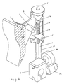
- the support curve with its storage in represented individual is on a lever arm 16 attached to a base bracket 1 at 4 is pivotally mounted.
- On the swivel arm 16 is a Toggle lever 6 pivotally attached at 3.
- the other end of the The toggle lever carries a spindle nut 5 which is pivotable this end of the toggle lever and in an elongated hole in the basic carrier is displaceable.
- a spindle 7 is mounted, which carries the spindle nut 5.
- a Knurled nut 8 serves to rotate the spindle 7.
- the base support 1 is on the machine frame by a Clamp holder 9 fastened by means of a clamping lever 12 can be determined and solved.
- the clamp holder 9 is adjustable relative to the base support 1, with a knurled nut 10 fixes the corresponding position.
- Three scales 13, 14 and 22 make it possible to determine the corresponding position.
- the spindle nut 5 in Direction of the spindle axis in the elongated hole of the base support 1 postponed. Due to the resulting pivoting movement of the Toggle lever 6 (change in distance between 4 and 5), the lever arm 16 is pivoted up and down with the support curve 2, the toggle lever 6 about the pivot axis 3 is pivotable.
- the entire base support 1 can be made using the clamp holder and its attachment up and down, i.e. in the direction of the axis the spindle (7) can be adjusted.
- the knurled nut must be used for this 10 can be solved.
- the scale 14 shows the position of the base support 1 relatively to the machine frame.
- the scale 13 shows the inclination the support curve 2.
- the spindle drive is designed and dimensioned so that a easy and fine adjustment is possible that this adjustment, i.e. the gear formed by the spindle drive but is self-locking so that the weight of the paper stack, the load on the support curve 2, an adjustment cannot bring about.
- the adjustment is only by actuation the knurled nut 8 possible.
Landscapes
- Engineering & Computer Science (AREA)
- Mechanical Engineering (AREA)
- Sheets, Magazines, And Separation Thereof (AREA)
Abstract
Description
- Fig. 1
- eine schematische Seitenansicht eines Friktionsanlegers mit den wesentlichen Bauteilen eines solchen Friktionsanlegers;
- Fig. 2
- eine perspektivische Ansicht der Stützkurve und des Getriebes zu ihrer Verstellung von vorne;
- Fig. 3
- eine der Fig. 2 entsprechende Ansicht, jedoch als Ansicht von hinten; und
- Fig. 4
- eine der Fig. 2 entsprechende Ansicht, jedoch teilweise geschnitten.
Claims (5)
- Friktionsanleger für Papierstapel oder dgl. mit einem Friktionsförderriemen (15) unterhalb des Papierstapels (19) und einer Stützkurve (2), an der die Papiere in dem Stapel mit Ihrer Rückseite anliegen und die in Ihrer Neigung zur Ebene der Papiere verstellbar ist, dadurch gekennzeichnet, daß an der Stützkurve (2) ein Kniehebel befestigt ist, der zur Verstellung der Neigung der Stützkurve durch ein selbsthemmendes Getriebe (5,7) schwenkbar ist.
- Friktionsanleger nach Anspruch 1, dadurch gekennzeichnet, daß das Getriebe durch eine Spindel (5) und eine Spindelmutter (7) gebildet ist, die an dem freien Ende des Kniehebels (6) um eine Achse schwenkbar gelagert ist, die senkrecht zu der Achse der Spindel (7) verläuft.
- Friktionsanleger nach Anspruch 2, dadurch gekennzeichnet, daß das andere, nicht der Lagerung der Spindelmutter (5) dienende Ende des Kniehebels (6) an einem zur Verstellung der Neigung der Stützkurve (2) schwenkbar gelagerten Hebelarm (16) ebenfalls schwenkbar gelagert (bei 3) ist.
- Friktionsanleger nach Anspruch 3, dadurch gekennzeichnet, daß die ortsfeste Lagerung der Spindel (7) in der Schwenkachse (4) des Hebelarmes (16) liegt.
- Friktionsanleger nach einem oder mehreren der vorstehenden Ansprüche, dadurch gekennzeichnet, daß die Stützkurve (2) zusammen mit dem Getriebe (Spindeltrieb 5,7) und der Lagerungen (3,4,5) in Richtung der Achse der Spindel (7) verstellbar ist.
Applications Claiming Priority (2)
| Application Number | Priority Date | Filing Date | Title |
|---|---|---|---|
| DE20009086U | 2000-05-19 | ||
| DE20009086U DE20009086U1 (de) | 2000-05-19 | 2000-05-19 | Friktionsanleger für Papierstapel o.dgl. |
Publications (3)
| Publication Number | Publication Date |
|---|---|
| EP1179496A2 true EP1179496A2 (de) | 2002-02-13 |
| EP1179496A3 EP1179496A3 (de) | 2004-08-18 |
| EP1179496B1 EP1179496B1 (de) | 2006-06-21 |
Family
ID=7941794
Family Applications (1)
| Application Number | Title | Priority Date | Filing Date |
|---|---|---|---|
| EP01108906A Expired - Lifetime EP1179496B1 (de) | 2000-05-19 | 2001-04-10 | Friktionsanleger für Papierstapel oder dgl. |
Country Status (3)
| Country | Link |
|---|---|
| US (1) | US6416047B1 (de) |
| EP (1) | EP1179496B1 (de) |
| DE (2) | DE20009086U1 (de) |
Cited By (1)
| Publication number | Priority date | Publication date | Assignee | Title |
|---|---|---|---|---|
| WO2005105630A3 (en) * | 2004-05-03 | 2006-02-02 | Zih Corp | Feeder device having increased media capacity and multiple media thickness feed capability and associated method |
Families Citing this family (9)
| Publication number | Priority date | Publication date | Assignee | Title |
|---|---|---|---|---|
| US6698748B1 (en) * | 2000-09-25 | 2004-03-02 | H. W. Crowley | System and method for singulating a stack of sheet-like materials |
| US6585257B2 (en) * | 2001-04-03 | 2003-07-01 | Pitney Bowes Inc. | Sheet feeder with counteracting forces |
| AU2003300045A1 (en) * | 2002-12-31 | 2004-07-29 | Shuttleworth, Inc. | Compression passing roller |
| US7008588B2 (en) * | 2003-07-11 | 2006-03-07 | General Electric Company | Apparatus and method for forming panels from moldable material |
| DE102009042469B3 (de) * | 2009-09-23 | 2011-01-27 | Köra-Packmat Maschinenbau GmbH | Reibanleger und Verstellplatte für einen Reibanleger |
| US9221629B1 (en) * | 2012-09-28 | 2015-12-29 | Superior Paper Handling Solutions, Inc. | Friction feeder |
| CN105540244B (zh) * | 2016-01-28 | 2017-12-12 | 江苏新美星包装机械股份有限公司 | 纸箱裹包机中的进纸装置 |
| US10640312B2 (en) | 2017-12-21 | 2020-05-05 | Superior Product Handling Solutions, Inc. | Friction feeding separating system |
| CN110143013B (zh) * | 2019-06-13 | 2020-11-06 | 安徽世品佳工业产品设计有限公司 | 纸板导出装置 |
Family Cites Families (8)
| Publication number | Priority date | Publication date | Assignee | Title |
|---|---|---|---|---|
| US3034784A (en) * | 1960-06-10 | 1962-05-15 | Universal Corrugated Box Mach | Feeding equipment |
| US3748937A (en) * | 1971-07-01 | 1973-07-31 | Longford Equip Intern Ltd | Card scoring device |
| US3908983A (en) * | 1973-02-07 | 1975-09-30 | John Albert Long | Card feeder |
| DE2946426C2 (de) * | 1979-11-16 | 1984-05-03 | Jagenberg-Werke AG, 4000 Düsseldorf | Vorrichtung zum Vereinzeln von gestapelten Zuschnitten aus Karton o.dgl. |
| US5244198A (en) * | 1992-04-28 | 1993-09-14 | Green Ronald J | Gate forming member for sheet feeding apparatus |
| DE4424450C1 (de) * | 1994-07-12 | 1995-10-19 | Pfankuch Maschinen Gmbh | Vorrichtung zum Sammeln einer vorbestimmten Anzahl von Zuschnitten |
| US6050562A (en) * | 1998-06-23 | 2000-04-18 | Long; John Albert | Stacked sheet feeder |
| US6050563A (en) * | 1998-03-02 | 2000-04-18 | Multifeeder Technology, Inc. | Sheet feeder |
-
2000
- 2000-05-19 DE DE20009086U patent/DE20009086U1/de not_active Expired - Lifetime
- 2000-08-16 US US09/640,306 patent/US6416047B1/en not_active Expired - Fee Related
-
2001
- 2001-04-10 EP EP01108906A patent/EP1179496B1/de not_active Expired - Lifetime
- 2001-04-10 DE DE50110215T patent/DE50110215D1/de not_active Expired - Lifetime
Cited By (1)
| Publication number | Priority date | Publication date | Assignee | Title |
|---|---|---|---|---|
| WO2005105630A3 (en) * | 2004-05-03 | 2006-02-02 | Zih Corp | Feeder device having increased media capacity and multiple media thickness feed capability and associated method |
Also Published As
| Publication number | Publication date |
|---|---|
| EP1179496B1 (de) | 2006-06-21 |
| US6416047B1 (en) | 2002-07-09 |
| DE50110215D1 (de) | 2006-08-03 |
| EP1179496A3 (de) | 2004-08-18 |
| DE20009086U1 (de) | 2001-09-27 |
Similar Documents
| Publication | Publication Date | Title |
|---|---|---|
| DE3433793C2 (de) | ||
| EP0475890B1 (de) | Wischvorrichtung für den Plattenzylinder einer Stichtiefdruckmaschine | |
| EP0046225B1 (de) | Vorrichtung zum Aufstellen eines Datensichtgerätes auf einer Arbeitsfläche | |
| EP1179496A2 (de) | Friktionsanleger für Papierstapel oder dgl. | |
| EP0538638B1 (de) | Vorrichtung zur Vorderkantenausrichtung | |
| DE3636814C2 (de) | ||
| DE3047277A1 (de) | "ablagevorrichtung fuer datentraeger" | |
| DE19938069C2 (de) | Kuvertiereinrichtung für Postbearbeitungsmaschinen | |
| EP0169608A2 (de) | Vorrichtung an einem Einzelblattabzug für Drucker und dergleicen | |
| EP0190629B1 (de) | Abreissvorrichtung für Papierbahnen oder Einzelblätter in Büromaschinen, insbesondere in Matrixdruckern | |
| DE102004038753B3 (de) | Vorrichtung zum Vereinzeln von Blättern eines Aufzeichnungsträgers | |
| DE3443735A1 (de) | Blattstapel-vorratsmagazin | |
| EP0027859B1 (de) | Ablagehilfe für Papierabschneideeinrichtungen | |
| DE2913594A1 (de) | Vorrichtung zum transportieren von blattfoermigen aufzeichnungstraegern | |
| DE19938878A1 (de) | An eine Leimwalze anschwenkbarer, ein- oder mehrteiliger Leimschaber in einer Etikettiermaschine für Behälter, insbesondere Flaschen | |
| WO2021097513A1 (de) | Zubehörvorrichtung | |
| DD280308A1 (de) | Anlegmarke | |
| EP0826498B1 (de) | Tampondruckmaschine | |
| DE1883031U (de) | Einstellbarer registeranschlag. | |
| EP0269976B1 (de) | Vorrichtung zur Halterung eines Matrixdruckkopfes | |
| DE2131258A1 (de) | Vorrichtung zur Beschickung eines Anlegers | |
| DE2606697C3 (de) | Vorrichtung zum Vereinzeln von Aufzeichnungsträgern | |
| DE2320324B2 (de) | Vorrichtung zum Aufschneiden von Briefumschlagen | |
| DE10101185B4 (de) | Spulvorrichtung für eine Kreuzspulen herstellende Textilmaschine | |
| DE8814238U1 (de) | Druckvorrichtung |
Legal Events
| Date | Code | Title | Description |
|---|---|---|---|
| PUAI | Public reference made under article 153(3) epc to a published international application that has entered the european phase |
Free format text: ORIGINAL CODE: 0009012 |
|
| AK | Designated contracting states |
Kind code of ref document: A2 Designated state(s): AT BE CH CY DE DK ES FI FR GB GR IE IT LI LU MC NL PT SE TR |
|
| AX | Request for extension of the european patent |
Free format text: AL;LT;LV;MK;RO;SI |
|
| PUAL | Search report despatched |
Free format text: ORIGINAL CODE: 0009013 |
|
| AK | Designated contracting states |
Kind code of ref document: A3 Designated state(s): AT BE CH CY DE DK ES FI FR GB GR IE IT LI LU MC NL PT SE TR |
|
| AX | Request for extension of the european patent |
Extension state: AL LT LV MK RO SI |
|
| RIC1 | Information provided on ipc code assigned before grant |
Ipc: 7B 65H 1/24 B Ipc: 7B 65H 3/34 B Ipc: 7B 65H 3/04 A |
|
| 17P | Request for examination filed |
Effective date: 20040903 |
|
| AKX | Designation fees paid |
Designated state(s): DE FR GB IT |
|
| GRAP | Despatch of communication of intention to grant a patent |
Free format text: ORIGINAL CODE: EPIDOSNIGR1 |
|
| GRAS | Grant fee paid |
Free format text: ORIGINAL CODE: EPIDOSNIGR3 |
|
| GRAA | (expected) grant |
Free format text: ORIGINAL CODE: 0009210 |
|
| AK | Designated contracting states |
Kind code of ref document: B1 Designated state(s): DE FR GB IT |
|
| PG25 | Lapsed in a contracting state [announced via postgrant information from national office to epo] |
Ref country code: IT Free format text: LAPSE BECAUSE OF FAILURE TO SUBMIT A TRANSLATION OF THE DESCRIPTION OR TO PAY THE FEE WITHIN THE PRESCRIBED TIME-LIMIT;WARNING: LAPSES OF ITALIAN PATENTS WITH EFFECTIVE DATE BEFORE 2007 MAY HAVE OCCURRED AT ANY TIME BEFORE 2007. THE CORRECT EFFECTIVE DATE MAY BE DIFFERENT FROM THE ONE RECORDED. Effective date: 20060621 |
|
| REG | Reference to a national code |
Ref country code: GB Ref legal event code: FG4D Free format text: NOT ENGLISH |
|
| REF | Corresponds to: |
Ref document number: 50110215 Country of ref document: DE Date of ref document: 20060803 Kind code of ref document: P |
|
| GBT | Gb: translation of ep patent filed (gb section 77(6)(a)/1977) |
Effective date: 20060907 |
|
| ET | Fr: translation filed | ||
| PLBE | No opposition filed within time limit |
Free format text: ORIGINAL CODE: 0009261 |
|
| STAA | Information on the status of an ep patent application or granted ep patent |
Free format text: STATUS: NO OPPOSITION FILED WITHIN TIME LIMIT |
|
| 26N | No opposition filed |
Effective date: 20070322 |
|
| PGFP | Annual fee paid to national office [announced via postgrant information from national office to epo] |
Ref country code: DE Payment date: 20100507 Year of fee payment: 10 |
|
| PGFP | Annual fee paid to national office [announced via postgrant information from national office to epo] |
Ref country code: FR Payment date: 20110511 Year of fee payment: 11 |
|
| PGFP | Annual fee paid to national office [announced via postgrant information from national office to epo] |
Ref country code: GB Payment date: 20110428 Year of fee payment: 11 |
|
| PGFP | Annual fee paid to national office [announced via postgrant information from national office to epo] |
Ref country code: IT Payment date: 20110429 Year of fee payment: 11 |
|
| GBPC | Gb: european patent ceased through non-payment of renewal fee |
Effective date: 20120410 |
|
| REG | Reference to a national code |
Ref country code: FR Ref legal event code: ST Effective date: 20121228 |
|
| PG25 | Lapsed in a contracting state [announced via postgrant information from national office to epo] |
Ref country code: GB Free format text: LAPSE BECAUSE OF NON-PAYMENT OF DUE FEES Effective date: 20120410 |
|
| REG | Reference to a national code |
Ref country code: DE Ref legal event code: R119 Ref document number: 50110215 Country of ref document: DE Effective date: 20121101 |
|
| PG25 | Lapsed in a contracting state [announced via postgrant information from national office to epo] |
Ref country code: FR Free format text: LAPSE BECAUSE OF NON-PAYMENT OF DUE FEES Effective date: 20120430 Ref country code: IT Free format text: LAPSE BECAUSE OF NON-PAYMENT OF DUE FEES Effective date: 20120410 |
|
| PG25 | Lapsed in a contracting state [announced via postgrant information from national office to epo] |
Ref country code: DE Free format text: LAPSE BECAUSE OF NON-PAYMENT OF DUE FEES Effective date: 20121101 |