EP1179296A2 - Vorrichtung zur Simulation einer lebenden Taube - Google Patents
Vorrichtung zur Simulation einer lebenden Taube Download PDFInfo
- Publication number
- EP1179296A2 EP1179296A2 EP01103160A EP01103160A EP1179296A2 EP 1179296 A2 EP1179296 A2 EP 1179296A2 EP 01103160 A EP01103160 A EP 01103160A EP 01103160 A EP01103160 A EP 01103160A EP 1179296 A2 EP1179296 A2 EP 1179296A2
- Authority
- EP
- European Patent Office
- Prior art keywords
- pigeon
- bearing plate
- support arms
- arm
- wing
- Prior art date
- Legal status (The legal status is an assumption and is not a legal conclusion. Google has not performed a legal analysis and makes no representation as to the accuracy of the status listed.)
- Withdrawn
Links
- 241000272201 Columbiformes Species 0.000 title claims abstract description 58
- 230000000284 resting effect Effects 0.000 claims abstract description 3
- 238000004088 simulation Methods 0.000 claims description 6
- 230000005540 biological transmission Effects 0.000 claims description 4
- 241000531763 Otididae Species 0.000 description 2
- 230000002349 favourable effect Effects 0.000 description 1
- 230000002093 peripheral effect Effects 0.000 description 1
Images

Classifications
-
- A—HUMAN NECESSITIES
- A01—AGRICULTURE; FORESTRY; ANIMAL HUSBANDRY; HUNTING; TRAPPING; FISHING
- A01M—CATCHING, TRAPPING OR SCARING OF ANIMALS; APPARATUS FOR THE DESTRUCTION OF NOXIOUS ANIMALS OR NOXIOUS PLANTS
- A01M29/00—Scaring or repelling devices, e.g. bird-scaring apparatus
- A01M29/06—Scaring or repelling devices, e.g. bird-scaring apparatus using visual means, e.g. scarecrows, moving elements, specific shapes, patterns or the like
-
- A—HUMAN NECESSITIES
- A01—AGRICULTURE; FORESTRY; ANIMAL HUSBANDRY; HUNTING; TRAPPING; FISHING
- A01M—CATCHING, TRAPPING OR SCARING OF ANIMALS; APPARATUS FOR THE DESTRUCTION OF NOXIOUS ANIMALS OR NOXIOUS PLANTS
- A01M31/00—Hunting appliances
- A01M31/06—Decoys
Definitions
- the invention relates to a device for simulation a living pigeon with a picture, by means of which the The body of a shot pigeon is receivable and presentable and the wing holders assigned to the wings of the hunted pigeon having.
- pigeon bustards are said to be especially wild pigeons Places to be lured where the shooting of these wild pigeons can take place under particularly favorable circumstances.
- the shooting of such wild pigeons is during certain periods required because these wild pigeons are still on the stock Reduce field agricultural products.
- the invention has for its object a device to simulate a live pigeon using the Pigeons, especially wild pigeons, can be attracted better.
- Wing holder holding the device for simulating a live pigeon so movable with respect to the recording are that by means of them and those resting in them Wings of the killed pigeon the wing movement of an approaching Pigeon can be reproduced.
- the wing holders on each support arm are advantageous fixed, which in turn between an upper high position, in which it forms a positive angle with the horizontal, and a low subscript in which he is level with the horizontal forms a negative angle, is adjustable.
- Movement of the support arms can thus be the wing holder and thus the wings held by the wing holders or dead pigeon, especially wild pigeon, in a simple manner be moved.
- the two support arms are expediently attached to one another facing end sections by means of a common Pivot pin pivotally connected to each other. By swiveling the two support arms in opposite directions the pivot can then move the two wings of the shot pigeon that are required to simulate the approach of a pigeon that is still alive.
- the pivot pin common to the two support arms is advantageous movable in the vertical direction.
- each support arm has an elongated hole, in each of which a bearing plate side Pilot protrudes.
- the two support arms are common Pivots arranged on an end portion of an actuating arm is, which in turn is movable in the vertical direction.
- a simple grill motor can advantageously be used as the electric motor or the like. be provided.
- control arm is above the pigeon Pivot pin a holding member for the neck or head of the shot Pigeon, then the neck or head the dead or shot pigeon by means of the invention Device can be moved.
- Device for simulating a live pigeon is on a holding cup on the side of the bearing plate facing away from the actuating arm arranged for the hull of the killed pigeon.
- the pivot pin is less expensive to construct To ensure way is in the upper edge of the bearing plate formed a recess in which the two Support and pivot arm connecting the actuating arm movable is.
- the electric motor of the device according to the invention and rotatable output member can advantageously on different Sides of the bearing plate can be arranged, where appropriate are connected by means of a transmission shaft, which extends through an opening in the bearing plate.
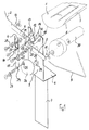
- a device shown in FIGS. 1 to 3 for Simulation of a live pigeon has in the illustrated embodiment a three-part recording for the body one already killed pigeon.
- This recording only partially includes one in FIG. 1 shown holding shell 1, two wing holders 2, 3 and a holding member 4.
- the holding shell 1 serves the trunk of the pigeon shot take.
- the wing holders 2, 3 act accordingly Recording as receiving elements for the two wings of the already shot pigeon.
- the neck or the head of the already killed pigeon By means of the holding member 4, the neck or the head of the already killed pigeon.
- the recording 1, 2, 3, 4 should be such that means you reproduced the wing movement of a flying pigeon are the above components the recording, namely the holding shell 1, the wing holder 2, 3 and the holding member 4 in the described below Arranged or connected to each other in a manner.
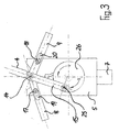
- the holding shell 1 is suitably on the back a vertically arranged bearing plate 5 is provided.
- the bearing plate 5 is angled at its lower end Approach 6 provided that can be trained on any length Stand 7 is placed.
- movable Support arms 8, 9 arranged, the support arm 8 by means of a Screw connection 10 with the wing holder 2 and the support arm 9 by means of a screw connection 11 with the wing holder 3 connected is.
- the connection between the support arms 8, 9 and the wing holders 2, 3 is designed such that the Wing holders 2, 3 move together with the support arms 8, 9.
- the screw connections 10, 11 are at the outer ends of the Support arms 8, 9 are provided.
- the bearing plate 5 has two on its front Guide pins 17, 18 formed in the support arms 8, 9 Project through elongated holes 19, 20 and form part of another Bolt connection 21 and 22 are.
- the above-mentioned actuating arm is on his in figure 1 upper end with a bore 23 which with the Bores 12, 13 of the two support arms 8, 9 are aligned and the is also penetrated by the pivot pin 14.
- Above the bore 23 is the actuating arm 15 in the case in FIGS to 3 illustrated embodiment of the invention Device provided in one piece with the holding member 4, which holds the neck or head of the killed pigeon.
- the actuating arm has at its in the figure 1 to 3 lower end of a further bore 24, the one Eccentric pin 25 is penetrated.
- the eccentric pin 25 is Part of an actuating arm 15 pivotable on an output member 26 fixing further bolt connection 27th
- the output member 26 is on the front of the bearing plate 5 arranged and by means of a transmission shaft 28, the one Passing through opening 29 in the bearing plate 5, in rotational connection with an electric motor designed as a grill motor 30 on the back of the bearing plate 5 in one area arranged below the holding shell 1 also provided there is.
Landscapes
- Life Sciences & Earth Sciences (AREA)
- Engineering & Computer Science (AREA)
- Insects & Arthropods (AREA)
- Pest Control & Pesticides (AREA)
- Wood Science & Technology (AREA)
- Zoology (AREA)
- Environmental Sciences (AREA)
- Birds (AREA)
- Catching Or Destruction (AREA)
- Toys (AREA)
Abstract
Description
- Figur 1
- eine perspektivische Explosionsdarstellung einer Ausführungsform der erfindungsgemäßen Vorrichtung zur Simulation einer lebenden Taube;
- Figur 2
- eine Vorderansicht der in Figur 1 gezeigten Vorrichtung zur Simulation einer lebenden Taube, wobei sich Flügelhalter der Vorrichtung in einer Hochstellung befinden; und
- Figur 3
- eine Figur 2 entsprechende Darstellung der erfindungsgemäßen Vorrichtung, wobei sich Flügelhalter der Vorrichtung in einer Tiefstellung befinden.
Claims (13)
- Vorrichtung zur Simulation einer lebenden Taube, mit einer Aufnahme (1, 2, 3, 4), mittels der der Körper einer erlegten Taube aufnehm- und präsentierbar ist und die den Flügeln der erlegten Taube zugeordnete Flügelhalter (2, 3) aufweist, dadurch gekennzeichnet, daß die Flügelhalter (2, 3) in bezug auf die Aufnahme (1, 2, 3, 4) so bewegbar angeordnet sind, daß mittels ihnen und der in ihnen ruhenden Flügel der erlegten Taube die Flügelbewegung einer anfliegenden Taube nachbildbar ist.
- Vorrichtung nach Anspruch 1, bei der die Flügelhalter (2, 3) an jeweils einem Stützarm (8, 9) fixiert sind, der seinerseits zwischen einer oberen Hochstellung, in der er mit der Horizontalen einen positiven Winkel bildet, und einer niedrigen Tiefstellung, in der er mit der Horizontalen einen negativen Winkel bildet, verstellbar ist.
- Vorrichtung nach Anspruch 2, bei der die beiden Stützarme (8, 9) an ihren einander zugewandten Endabschnitten mittels eines ihnen gemeinsamen Schwenkzapfens (14) zueinander verschwenkbar miteinander verbunden sind.
- Vorrichtung nach Anspruch 3, bei der der beiden Stützarmen (8, 9) gemeinsame Schwenkzapfen (14) in Vertikalrichtung bewegbar ist.
- Vorrichtung nach einem der Ansprüche 2 bis 4, bei der die beiden Stützarme (8, 9) jeweils in ihrer Längsrichtung verschieblich an einer Lagerplatte (5) gehaltert sind.
- Vorrichtung nach Anspruch 5, bei der jeder Stützarm (8, 9) ein Langloch (19, 20) aufweist, in das jeweils ein lagerplattenseitiger Führzapfen (17, 18) vorsteht.
- Vorrichtung nach einem der Ansprüche 3 bis 6, bei der der beiden Stützarmen (8, 9) gemeinsame Schwenkzapfen (14) an einem Endabschnitt eines Stellarms (15) angeordnet ist, der in Vertikalrichtung bewegbar ist.
- Vorrichtung nach Anspruch 7, bei der der Stellarm (15) an seinem schwenkzapfenfreien Endabschnitt mit einem Exzenterzapfen (25) eines drehbaren Ausgangsglieds (26) eines Elektromotors (30) verbunden ist.
- Vorrichtung nach Anspruch 8, bei der der Elektromotor (30) als Grillmotor od.dgl. ausgebildet ist.
- Vorrichtung nach einem der Ansprüche 7 bis 9, bei der der Stellarm (15) oberhalb des Schwenkzapfens (14) ein Halteglied (4) für den Hals bzw. Kopf der erlegten Taube aufweist.
- Vorrichtung nach einem der Ansprüche 7 bis 10, bei der auf der dem Stellarm (15) abgewandten Seite der Lagerplatte (5) eine Halteschale (1) für den Rumpf der erlegten Taube angeordnet ist.
- Vorrichtung nach einem der Ansprüche 7 bis 11, bei der in der Oberkante (31) der Lagerplatte (5) eine Ausnehmung (32) ausgebildet ist, in der der die beiden Stütz-(8, 9) und den Stellarm (15) verbindende Schwenkzapfen (14) bewegbar ist.
- Vorrichtung nach einem der Ansprüche 8 bis 12, bei der der Elektromotor (30) und sein drehbares Ausgangsglied (26) auf unterschiedlichen Seiten der Lagerplatte (5) angeordnet und mittels einer Übertragungswelle (28), die eine Öffnung (29) der Lagerplatte (5) durchragt, miteinander verbunden sind.
Applications Claiming Priority (2)
| Application Number | Priority Date | Filing Date | Title |
|---|---|---|---|
| DE20013571U DE20013571U1 (de) | 2000-08-08 | 2000-08-08 | Vorrichtung zur Simulation einer lebenden Taube |
| DE20013571U | 2000-08-08 |
Publications (2)
| Publication Number | Publication Date |
|---|---|
| EP1179296A2 true EP1179296A2 (de) | 2002-02-13 |
| EP1179296A3 EP1179296A3 (de) | 2002-06-12 |
Family
ID=7944866
Family Applications (1)
| Application Number | Title | Priority Date | Filing Date |
|---|---|---|---|
| EP01103160A Withdrawn EP1179296A3 (de) | 2000-08-08 | 2001-02-10 | Vorrichtung zur Simulation einer lebenden Taube |
Country Status (2)
| Country | Link |
|---|---|
| EP (1) | EP1179296A3 (de) |
| DE (1) | DE20013571U1 (de) |
Cited By (10)
| Publication number | Priority date | Publication date | Assignee | Title |
|---|---|---|---|---|
| US7082710B1 (en) * | 2004-08-17 | 2006-08-01 | Jorgenson Marty L | Decoy support system |
| US7225579B2 (en) * | 2005-09-08 | 2007-06-05 | Patrick Haley | Wing structure for a waterfowl decoy |
| US7272905B1 (en) * | 2006-10-03 | 2007-09-25 | Horton Albert E | Turkey decoy system |
| US7287352B1 (en) * | 2004-09-23 | 2007-10-30 | Kirby Richard C | Decoy with movable head and/or tail portions |
| US7409793B1 (en) * | 2007-02-26 | 2008-08-12 | Walter Jack Schwarz | Waterfowl decoy accessory |
| US7627977B2 (en) * | 2006-09-29 | 2009-12-08 | Arthur Denny | Animated wildfowl decoy |
| US8316575B2 (en) * | 2008-03-14 | 2012-11-27 | Bradley Gerald R | Swivel mount for bird-shaped decoys |
| US20130239454A1 (en) * | 2012-03-13 | 2013-09-19 | Keith Dominick Szechenyi | Motion decoy with biaxial wing beat |
| US20140144062A1 (en) * | 2012-11-27 | 2014-05-29 | WGl lnnovations, Ltd. | Electrical decoy apparatus |
| US12302891B1 (en) * | 2020-09-16 | 2025-05-20 | Expedite International | Spinning wing decoy technology |
Families Citing this family (2)
| Publication number | Priority date | Publication date | Assignee | Title |
|---|---|---|---|---|
| GB0118359D0 (en) * | 2001-07-27 | 2001-09-19 | Cosciani Roberto | Decoy and movement system for the same |
| FR3071703A1 (fr) * | 2017-10-02 | 2019-04-05 | Plumaffut | Dispositif de glanage pour la chasse aux oiseaux par appelant |
Family Cites Families (3)
| Publication number | Priority date | Publication date | Assignee | Title |
|---|---|---|---|---|
| US2480390A (en) * | 1947-07-03 | 1949-08-30 | Paul D Thompson | Animated decoy and actuating mechanism therefor |
| US4896448A (en) * | 1988-12-20 | 1990-01-30 | Jackson Larry L | Bird decoy with motor drive wings |
| US5809683A (en) * | 1996-07-05 | 1998-09-22 | Solomon; Walter | Battery-powered apparatus to provide movable wings and feet on waterfowl decoys, including method of assembly |
-
2000
- 2000-08-08 DE DE20013571U patent/DE20013571U1/de not_active Expired - Lifetime
-
2001
- 2001-02-10 EP EP01103160A patent/EP1179296A3/de not_active Withdrawn
Cited By (14)
| Publication number | Priority date | Publication date | Assignee | Title |
|---|---|---|---|---|
| US7082710B1 (en) * | 2004-08-17 | 2006-08-01 | Jorgenson Marty L | Decoy support system |
| US7287352B1 (en) * | 2004-09-23 | 2007-10-30 | Kirby Richard C | Decoy with movable head and/or tail portions |
| US7225579B2 (en) * | 2005-09-08 | 2007-06-05 | Patrick Haley | Wing structure for a waterfowl decoy |
| US7627977B2 (en) * | 2006-09-29 | 2009-12-08 | Arthur Denny | Animated wildfowl decoy |
| US7272905B1 (en) * | 2006-10-03 | 2007-09-25 | Horton Albert E | Turkey decoy system |
| US7409793B1 (en) * | 2007-02-26 | 2008-08-12 | Walter Jack Schwarz | Waterfowl decoy accessory |
| US8316575B2 (en) * | 2008-03-14 | 2012-11-27 | Bradley Gerald R | Swivel mount for bird-shaped decoys |
| US20130239454A1 (en) * | 2012-03-13 | 2013-09-19 | Keith Dominick Szechenyi | Motion decoy with biaxial wing beat |
| US9258993B2 (en) * | 2012-03-13 | 2016-02-16 | Evolution Decoys Llc | Motion decoy with biaxial wing beat |
| US20160120169A1 (en) * | 2012-03-13 | 2016-05-05 | Keith Dominick Szechenyi | Motion decoy with biaxial wing beat |
| US9717236B2 (en) * | 2012-03-13 | 2017-08-01 | Evolution Decoys, Llc | Motion decoy with biaxial wing beat |
| US20140144062A1 (en) * | 2012-11-27 | 2014-05-29 | WGl lnnovations, Ltd. | Electrical decoy apparatus |
| US9101128B2 (en) * | 2012-11-27 | 2015-08-11 | Christopher B. Barley | Electrical decoy apparatus |
| US12302891B1 (en) * | 2020-09-16 | 2025-05-20 | Expedite International | Spinning wing decoy technology |
Also Published As
| Publication number | Publication date |
|---|---|
| EP1179296A3 (de) | 2002-06-12 |
| DE20013571U1 (de) | 2001-04-05 |
Similar Documents
| Publication | Publication Date | Title |
|---|---|---|
| DE10039740C1 (de) | Lautsprecherboxenanordnung | |
| EP1179296A2 (de) | Vorrichtung zur Simulation einer lebenden Taube | |
| DE102015118174A1 (de) | Dichtungsvorrichtung für eine Schiebetür sowie damit versehene Schiebetür | |
| DE102014011090A1 (de) | Befestigungsbeschlag für eine Blende an einer offenen Stirnseite einer Schublade | |
| DE202012009218U1 (de) | Scharnier | |
| DE102008023640B4 (de) | Prüfhalter für Mikrochip | |
| DE10203269B4 (de) | Beschlagvorrichtung für eine Möbelklappe | |
| DE924959C (de) | Ventilsteuerung, insbesondere fuer Brennkraftmaschinen | |
| DE60223944T2 (de) | Gelenkkonstruktion | |
| DE2829727A1 (de) | Moebelbeschlag | |
| DE917055C (de) | Lager fuer Fenster mit einem um eine waagerechte Achse schwenkbaren Fluegel | |
| DE102009057711B4 (de) | Tischklappenbeschlag | |
| DE202008010012U1 (de) | Klappenhalter für eine Möbelklappe | |
| CH188825A (de) | Vorrichtung zum Öffnen und Schliessen von Klappfenstern, Klapptüren usw. | |
| DE69605581T2 (de) | Regalträgermittel mit Doppeleinstellung | |
| DE2625367C2 (de) | ||
| DE102005014924B4 (de) | Gelenkscharnier, insbesondere 4-Gelenkscharnier | |
| DE202020103271U1 (de) | Schießanlage | |
| EP2667088A1 (de) | Einbauleuchte | |
| DE202014009787U1 (de) | Tragarm zur beweglichen Aufhängung von Anbaugeräten | |
| DE10107202C1 (de) | Locktauben-Wippe | |
| EP3050607B1 (de) | Modelltraktor mit einer kupplung zur aufnahme wenigstens eines anbaugerätes und/oder anhängers | |
| EP2899347B1 (de) | Vorrichtung zur Verbindung eines bewegbaren Möbelteils wie Klappe, Tür oder dergleichen, mit einem feststehenden Möbelteil | |
| DE3514603A1 (de) | Tisch mit einem tischgestell | |
| DE202009017688U1 (de) | Ein in zwei Richtungen geöffneter Grill |
Legal Events
| Date | Code | Title | Description |
|---|---|---|---|
| PUAI | Public reference made under article 153(3) epc to a published international application that has entered the european phase |
Free format text: ORIGINAL CODE: 0009012 |
|
| AK | Designated contracting states |
Kind code of ref document: A2 Designated state(s): AT BE CH CY DE DK ES FI FR GB GR IE IT LI LU MC NL PT SE TR |
|
| AX | Request for extension of the european patent |
Free format text: AL;LT;LV;MK;RO;SI |
|
| PUAL | Search report despatched |
Free format text: ORIGINAL CODE: 0009013 |
|
| AK | Designated contracting states |
Kind code of ref document: A3 Designated state(s): AT BE CH CY DE DK ES FI FR GB GR IE IT LI LU MC NL PT SE TR |
|
| AX | Request for extension of the european patent |
Free format text: AL;LT;LV;MK;RO;SI |
|
| 17P | Request for examination filed |
Effective date: 20021114 |
|
| AKX | Designation fees paid |
Designated state(s): DE |
|
| RBV | Designated contracting states (corrected) |
Designated state(s): BE DE |
|
| 17Q | First examination report despatched |
Effective date: 20040913 |
|
| STAA | Information on the status of an ep patent application or granted ep patent |
Free format text: STATUS: THE APPLICATION IS DEEMED TO BE WITHDRAWN |
|
| 18D | Application deemed to be withdrawn |
Effective date: 20040901 |