EP1177920A2 - Dispositif automatique pour le démontage et le montage de pneumatiques, et appareil pour démonter les pneumatiques équipé avec celui-ci - Google Patents
Dispositif automatique pour le démontage et le montage de pneumatiques, et appareil pour démonter les pneumatiques équipé avec celui-ci Download PDFInfo
- Publication number
- EP1177920A2 EP1177920A2 EP01201986A EP01201986A EP1177920A2 EP 1177920 A2 EP1177920 A2 EP 1177920A2 EP 01201986 A EP01201986 A EP 01201986A EP 01201986 A EP01201986 A EP 01201986A EP 1177920 A2 EP1177920 A2 EP 1177920A2
- Authority
- EP
- European Patent Office
- Prior art keywords
- tyre
- wheel rim
- tool
- operating head
- bead
- Prior art date
- Legal status (The legal status is an assumption and is not a legal conclusion. Google has not performed a legal analysis and makes no representation as to the accuracy of the status listed.)
- Granted
Links
- 239000011324 bead Substances 0.000 claims abstract description 52
- 238000000605 extraction Methods 0.000 description 3
- 230000014759 maintenance of location Effects 0.000 description 2
- 230000006835 compression Effects 0.000 description 1
- 238000007906 compression Methods 0.000 description 1
- 230000000694 effects Effects 0.000 description 1
- 238000003780 insertion Methods 0.000 description 1
- 230000037431 insertion Effects 0.000 description 1
- 230000000284 resting effect Effects 0.000 description 1
Images


Classifications
-
- B—PERFORMING OPERATIONS; TRANSPORTING
- B60—VEHICLES IN GENERAL
- B60C—VEHICLE TYRES; TYRE INFLATION; TYRE CHANGING; CONNECTING VALVES TO INFLATABLE ELASTIC BODIES IN GENERAL; DEVICES OR ARRANGEMENTS RELATED TO TYRES
- B60C25/00—Apparatus or tools adapted for mounting, removing or inspecting tyres
- B60C25/01—Apparatus or tools adapted for mounting, removing or inspecting tyres for removing tyres from or mounting tyres on wheels
- B60C25/05—Machines
- B60C25/132—Machines for removing and mounting tyres
- B60C25/135—Machines for removing and mounting tyres having a tyre support or a tool, movable along wheel axis
- B60C25/138—Machines for removing and mounting tyres having a tyre support or a tool, movable along wheel axis with rotary motion of tool or tyre support
-
- B—PERFORMING OPERATIONS; TRANSPORTING
- B60—VEHICLES IN GENERAL
- B60C—VEHICLE TYRES; TYRE INFLATION; TYRE CHANGING; CONNECTING VALVES TO INFLATABLE ELASTIC BODIES IN GENERAL; DEVICES OR ARRANGEMENTS RELATED TO TYRES
- B60C25/00—Apparatus or tools adapted for mounting, removing or inspecting tyres
- B60C25/01—Apparatus or tools adapted for mounting, removing or inspecting tyres for removing tyres from or mounting tyres on wheels
- B60C25/05—Machines
- B60C25/0563—Tools interacting with the tyre and moved in relation to the tyre during operation
- B60C25/0578—Tools interacting with the tyre and moved in relation to the tyre during operation hooking only
-
- B—PERFORMING OPERATIONS; TRANSPORTING
- B60—VEHICLES IN GENERAL
- B60C—VEHICLE TYRES; TYRE INFLATION; TYRE CHANGING; CONNECTING VALVES TO INFLATABLE ELASTIC BODIES IN GENERAL; DEVICES OR ARRANGEMENTS RELATED TO TYRES
- B60C25/00—Apparatus or tools adapted for mounting, removing or inspecting tyres
- B60C25/01—Apparatus or tools adapted for mounting, removing or inspecting tyres for removing tyres from or mounting tyres on wheels
- B60C25/05—Machines
- B60C25/0563—Tools interacting with the tyre and moved in relation to the tyre during operation
- B60C25/0593—Multi-functional tools for performing at least two operations, e.g. bead breaking and bead seeking
Definitions
- This invention concerns in general those means, installed on tyre removal machines, which enable the tyre to be removed from and/or mounted on the wheel rim.
- machines comprising essentially a rotary platform of vertical axis provided with a self-centering device for locking the wheel rim, which is overlain by a support which supports, adjustable in height and in the horizontal direction, a tool arranged to interact with the tyre edge or bead, to urge it below, or extract it from, the flange of the wheel rim.
- said tool is positioned at the end of a vertical support bar which slides within the end seat of a horizontal arm, to which it can be locked in level.
- the horizontal arm itself slides in the end seat of a vertical plate which extends upwards from the machine base to the side of the platform which receives the tyre.
- Said horizontal arm is provided with means for locking it in the desired position.
- the known art teaches that to be able to remove a tyre from the wheel rim the first operation which the operator has to carry out is to detach the tyre bead from the bead retaining flange of the wheel rim using the bead release device with which tyre removal machines are usually provided. The operator then places the wheel, comprising the wheel rim and tyre, on the self-centering device and locks it in the working position.
- the operator positions the tool in contact with the flange of the wheel rim and, using a suitable lever, lifts the tyre bead above the working surface of the tool and then rotates the wheel rim while simultaneously pressing with one hand on that side of the tyre opposite that at which the tool is positioned, in order to enable the bead to position itself in the well of the wheel rim.
- the operator has to aid the escape of the bead using a lever, one end of which is inserted between the tyre edge and the flange of the wheel rim.
- the operator firstly locks the wheel rim on the self-centering device, then positions the tyre on the wheel rim and then by pressing on its upper side has to at least partially insert the lower bead of the tyre into the wheel rim. At this point the operator locates the tool in its working position, and in particular has to position a part of the tyre bead below the working surface of the tool. He then rotates the self-centering device and with his hands, by pressing on the side of the tyre, aids the insertion of the bead into the bead retaining flange of the wheel rim.
- An object of the present invention is to overcome the drawbacks of the known art within the framework of a rational and reliable solution, which does not require the operator to intervene actively during the removal of the tyre from the wheel rim, or during the opposite operation.
- a further object of the invention is to provide a device which accelerates the tyre mounting and removal operations.
- the invention attains said objects by virtue of an automatic device for mounting and removing the tyre on/from the wheel rim which, associated with rotary means for supporting the wheel rim, is able to extract and/or insert the tyre from/into the wheel rim without requiring any operator intervention.
- the device comprises an operating head provided with at least one demounting tool, which can rotate about the main axis of said operating head, and is arranged to grip the tyre and then extract it from the wheel rim, and at least one mounting tool arranged to insert the tyre into the wheel rim.
- said at least one demounting tool can rotate about the main axis of said operating head to position itself between at least one first position in which the tyre bead is gripped and at least one second position in which the tyre bead is extracted from the wheel rim.
- Said operating head can rotate about its axis, and is associated with means which enable it to translate horizontally and vertically in such a manner as to position the demounting and mounting tools in proximity to the flange of the wheel rim.
- the wheel rim support means must preferably be such as to leave both flanges of the wheel rim free, so that the device of the invention can act simultaneously on both sides of the wheel rim.
- Said wheel rim support means can translate horizontally to approach and withdraw from the device of the invention in accordance with the wheel rim diameter and possibly the operating position assumed by the demounting tool.
- the combination of the device of the invention with said rotary support means for the wheel rim results in an assembly representing a complete tyre removal machine which can also be easily provided with a bead release tool of known type.
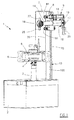
- Said figures show the tyre removal machine 1, which comprises a lower base 2, from the upper surface of which there projects a rotary shaft 3 for supporting the support and a locking means 4 for the wheel rim 5 on which the tyre 6 is installed.
- the shaft 3, and hence also the support and locking means 4 for the wheel rim 5, can translate axially, operated by means, known per se and not shown, positioned inside the casing 2.
- a vertical frame 7 provided with guides 70 for the sliding of an automatic device 9 for mounting and removing the tyre 6 on/from the wheel rim 5.
- the device 9 comprises a carriage 8 provided with four wheels 81 arranged to run on guides 70 of the vertical frame 71; the carriage 8 supports the means, described hereinafter, for mounting and removing the tyre 6 onto/from the wheel rim 5.
- the carriage 8 is driven vertically by a male-female screw mechanism 10, of which the female screw, not shown, is rigid with the carriage 8.
- the male screw 100 of the screw mechanism 10, shown in Figures 1 and 2 is fixed to the carriage 8 and is rotated by the electric motor 11. Rotation of the screw 100 hence causes the carriage 8 to translate vertically.
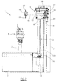
- a member 12 On the carriage 8 there is fixed a member 12, provided with a through hole 13 in which a hollow shaft 14 is inserted and slides, and of which one of its ends carries the operating head 12 and its opposite end is fixed to the cylinder 170 of a cylinder-piston unit 17.
- the purpose of the cylinder-piston unit 17 is to position in at least two working positions a movable tyre-demounting tool 25 hinged to the operating head 16 and having its hook-shaped lower end projecting from the head.
- the hollow shaft 14 is made to translate axially by a pneumatic cylinder-piston unit 18 also rigid with the carriage 8, with its rod carrying at one end a plate 19 secured to the cylinder 170 of the cylinder-piston unit 17. Although secured to the plate 19, the cylinder-piston unit 17 is free to rotate about its own axis.
- Said plate 19 carries at its lower end a second pneumatic cylinder-piston unit 20, the rod of which is connected to a rack 21 in which there engages a pinion 22 rigid with the cylinder 170. Operation of the cylinder-piston unit 20 causes the rack 21 to move, resulting in rotation of the cylinder-piston unit 17 and the hollow shaft 14.
- the pneumatic cylinder-piston unit 17 is provided with a double piston consisting of a cup-shaped piece 23 which slides within the cylinder 170, and a disc 24 with which one end of the rod 171 is rigid, and which slides within said cup-shaped piece 23.
- the disc 24 is prevented from withdrawing from the cup-shaped piece 23 by a retention ring 250.
- the air is fed, by suitable pneumatic means, not shown, into the cylinder 170 via the conduit 172, and, via the conduit 173, into the chamber 175 bounded by the inner walls of the cup-shaped piece and by the disc 24.
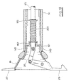
- the operating head 16 is of substantially frusto-conical form, and is internally hollow. It also presents an annular reduced-diameter portion 161 which is received in the end of the hollow shaft 14, and locked in position thereat by screws 140.
- Said annular reduced-diameter portion 161 is provided with a central stem 162 having a through central hole which also passes through said annular reduced-diameter portion 161, and is traversed by the free end of the rod 171.
- a compression spring 200 On the rod 171 there is mounted a compression spring 200, of which one end rests on said central stem 162 and its opposite end rests on a ring 163 locked onto the rod 171.
- the free end of the rod 171 is connected, via a connecting bar 30, to the upper end of the tyre demounting tool 25.
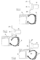
- the cylinder-piston unit 17 can dispose the tool 25 in different operating positions, namely a first position for seeking and gripping the tyre bead, and at least two positions for extracting the bead from the bead retaining flange of the wheel rim.
- the tool 15 when in the first position for seeking and gripping the tyre bead, the tool 15 is inclined at an angle a, of preferably between 2° and 15°, to the vertical axis passing through the centre of rotation of the tool.
- Figure 3 shows the first of the positions in which the tool 25 can extract the bead from the bead retaining flange of the wheel rim. This position also coincides with the tool rest position.
- the tool 25 When in said position the tool 25 is vertical, by virtue of the fact that compressed air is present in the chamber 175 to maintain the disc 24 against the retention ring 250, against the action of the spring 200.
- the air present in the chamber 175 is extracted. In this manner the spring 200 thrusts the disc 24 against the end of the cup-shaped piece 23, as shown in Figure 4.
- Figure 5 shows the second position for extracting the tyre bead from the bead retaining flange of the wheel rim.
- air is fed into the cylinder-piston unit 17 through the conduit 172.
- the cup-shaped piece 232 advances against the action of the spring 200 and rotates the tool 25 through an angle ⁇ , preferably between 1° and 40°.
- the shaft 3 is advanced in the tool direction by an amount equal to the chord subtended by the angle ⁇ at the hook-shaped end of the bead gripping tool 25.
- the operating head 16 is also provided with a fixed tool 27, used during the mounting of the tyre onto the wheel rim.
- the operation of the device can either be controlled by the operator using suitable control means, not shown, positioned on the casing 2 of the tyre removal machine, or be controlled automatically by a processor.
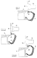
- the operator After releasing the bead of the tyre, the operator places the wheel on its support and locking means 4. When the wheel has been locked in position, the operator adjusts the position of the shaft 3 relative to the frame 7 on the basis of the wheel diameter. At this point he operates the device 9, which moves into the position shown in Figure 6, i.e. it positions the demounting tool 25 into proximity with the flange of the wheel rim, and specifically at 2 millimetres from said flange.
- the device 9 When in this position the device 9 is lowered through a predetermined amount, as shown in Figure 7, to insert its hook-shaped lower end between the bead retaining flange of the wheel rim and the tyre bead.
- the tool is moved into the bead seeking and gripping position ( Figure 8), i.e. it is rotated through an angle a to the vertical axis in the direction of the wheel rim, so that the hook-shaped end of the tool 25 grips the edge of the tyre bead.
- the tool is then returned to the first extraction position, coinciding with the (vertical) rest position, see Figure 9.
- the device 9 is raised from this position, as shown in Figure 10, to extract a portion of the tyre upper bead to above the wheel rim.
- the wheel rim is simultaneously rotated so that the entire upper bead leaves the wheel rim.
- the tool 25 can be repositioned in said second extraction position ( Figure 11). In this manner the tool 25 rotates in the opposite direction to that of the wheel rim through an angle ⁇ . Simultaneously, to prevent excessive tyre deformation, the shaft is advanced in the tool direction by an amount equal to the chord subtended by the angle ⁇ measured at the tyre bead gripping hook so that the tyre upper bead lies within the wheel rim diameter.
- the wheel rim 5 is then rotated so that the entire upper bead of the tyre 6 leaves the wheel rim.
- the tool When the tyre upper bead has been extracted, the tool is moved into its seeking position to release the tyre bead from it, after which the tool is returned to its rest position.
- the processor then withdraws the shaft 14 and lowers the carriage 8 to move the operating head 16 below the tyre. At this point the shaft 14 is made to rise to move the mounting tool 27 to a few millimetres from the lower flange of the wheel rim.
- the carriage is then raised to insert the tool 27 between the upper flange of the wheel rim and the tyre lower bead, with the sidewall of the tyre resting against the head 16. While rotating the wheel rim the shaft 14 is moved continuously upwards until the tyre has completely left the wheel rim.
- the tyre is mounted onto the wheel rim using the mounting tool 27.
- the operator rests the tyre on the wheel rim by inserting a part of the lower edge of the tyre bead into the well of the wheel rim such that the tyre axis is inclined to the vertical axis of the wheel rim.
- the operator moves the operating head 16 into proximity with the wheel rim flange so that the tool 27 becomes inserted between the upper flange of the wheel rim and the lower edge of the tyre. He then rotates the wheel rim and by lightly pressing on the tyre he causes the entire lower tyre bead to pass below the upper flange of the wheel rim.
Landscapes
- Engineering & Computer Science (AREA)
- Mechanical Engineering (AREA)
- Testing Of Balance (AREA)
- Tires In General (AREA)
- Tyre Moulding (AREA)
- Automatic Assembly (AREA)
Priority Applications (2)
| Application Number | Priority Date | Filing Date | Title |
|---|---|---|---|
| DE60106157T DE60106157T3 (de) | 2000-08-03 | 2001-05-28 | Automatische Radmontier- und Demontiervorrichtung und damit ausgestattetes Radmontagegerät |
| DE20121426U DE20121426U1 (de) | 2000-08-03 | 2001-05-28 | Automatische Reifendemontage- und Montagevorrichtung und damit verbundene Reifenmontiermaschinen |
Applications Claiming Priority (2)
| Application Number | Priority Date | Filing Date | Title |
|---|---|---|---|
| IT2000RE000078A IT1319475B1 (it) | 2000-08-03 | 2000-08-03 | Dispositivo automatico per lo smontaggio ed il montaggio deipneumatici, e macchine smontagomme cosi' attrezzate |
| ITRE200078 | 2000-08-03 |
Publications (4)
| Publication Number | Publication Date |
|---|---|
| EP1177920A2 true EP1177920A2 (fr) | 2002-02-06 |
| EP1177920A3 EP1177920A3 (fr) | 2002-12-18 |
| EP1177920B1 EP1177920B1 (fr) | 2004-10-06 |
| EP1177920B3 EP1177920B3 (fr) | 2010-06-02 |
Family
ID=11453953
Family Applications (1)
| Application Number | Title | Priority Date | Filing Date |
|---|---|---|---|
| EP01201986A Expired - Lifetime EP1177920B3 (fr) | 2000-08-03 | 2001-05-28 | Appareil pour démonter des pneumatiques équipé d'un dispositif automatique pour le démontage et le montage de pneumatiques |
Country Status (6)
| Country | Link |
|---|---|
| US (1) | US6619362B2 (fr) |
| EP (1) | EP1177920B3 (fr) |
| JP (1) | JP5069830B2 (fr) |
| DE (1) | DE60106157T3 (fr) |
| ES (1) | ES2230232T7 (fr) |
| IT (1) | IT1319475B1 (fr) |
Cited By (18)
| Publication number | Priority date | Publication date | Assignee | Title |
|---|---|---|---|---|
| EP1398184A1 (fr) * | 2002-09-13 | 2004-03-17 | CORGHI S.p.A. | Dispositif de démontage automatique de pneumatique et machine de démontage de pneumatique équipée avec |
| EP1459913A2 (fr) * | 2003-03-21 | 2004-09-22 | Snap-on Equipment S.r.l. | Dispositif de montage et démontage de pneumatiques |
| WO2004094168A1 (fr) | 2003-04-16 | 2004-11-04 | Societe De Technologie Michelin | Procede et dispositif pour effectuer un traitement sur un ensemble de composants d’une roue de vehicule |
| EP1607247A1 (fr) * | 2004-06-15 | 2005-12-21 | CORGHI S.p.A. | Dispositif décoinceur de talons |
| EP1625954A2 (fr) | 2004-07-30 | 2006-02-15 | Ennio Galbiati | Machine de démontage de pneumatiques avec outil multifonctions unique |
| CN101934689A (zh) * | 2009-06-30 | 2011-01-05 | 小野谷机工株式会社 | 胎圈拆卸臂及备有胎圈拆卸臂的轮胎拆卸装置及轮胎拆卸方法 |
| EP2484541A1 (fr) | 2011-02-08 | 2012-08-08 | CORGHI S.p.A. | Appareil de changement de pneus et procédé pour enlever un pneu d'une jante de roue correspondante |
| EP2650147A1 (fr) | 2012-04-11 | 2013-10-16 | CORGHI S.p.A. | Outil de démontage de pneumatique destiné à une machine pour démontage de pneumatique et ladite machine |
| EP2692553A1 (fr) | 2012-08-01 | 2014-02-05 | Butler Engineering & Marketing Spa | Dispositif de démontage d'un pneumatique sur une jante et procédé de démontage d'une roue à pneu |
| IT201600104507A1 (it) * | 2016-10-18 | 2018-04-18 | Nexion Spa | Macchina smontagomme |
| EP3315331A1 (fr) * | 2016-10-18 | 2018-05-02 | NEXION S.p.A. | Machine de changement de pneus |
| EP1714807B2 (fr) † | 2005-03-23 | 2019-03-27 | Butler Engineering & Marketing S.p.A. | Outil pour le démontage ou montage automatique de pneumatique sur/ d' une jante |
| IT201900019864A1 (it) | 2019-10-28 | 2021-04-28 | Beissbarth Gmbh | Macchina smontagomme |
| US20210155061A1 (en) * | 2019-11-27 | 2021-05-27 | Cemb S.P.A | Device for mounting and removing a tire on and from a rim |
| IT202100001238A1 (it) | 2021-01-25 | 2022-07-25 | Snap On Equip Srl Unico Socio | Apparato smontagomme |
| IT202100001235A1 (it) | 2021-01-25 | 2022-07-25 | Snap On Equip Srl Unico Socio | Apparato smontagomme con utensile a basculamento automatico |
| IT202100012638A1 (it) * | 2021-05-17 | 2022-11-17 | M & B Eng S R L | Dispositivo per il montaggio e lo smontaggio di un pneumatico su un cerchione |
| EP4067120A4 (fr) * | 2019-11-29 | 2024-01-03 | Yingkou Dali Automobile Maintenance Equipment S &T Co Ltd | Monte-démonte pneu |
Families Citing this family (31)
| Publication number | Priority date | Publication date | Assignee | Title |
|---|---|---|---|---|
| ITVR20010124A1 (it) * | 2001-11-22 | 2003-05-22 | Butler Enrineering & Marketing | Testa di stallonatura con unghia per il montaggio/smontaggio di un pneumatico per macchina smontagomme. |
| US8284390B1 (en) | 2003-02-20 | 2012-10-09 | Hunter Engineering Company | Vehicle tire changing system with tool positioning sensor |
| US7355687B2 (en) | 2003-02-20 | 2008-04-08 | Hunter Engineering Company | Method and apparatus for vehicle service system with imaging components |
| ITMO20030132A1 (it) * | 2003-05-09 | 2004-11-10 | Giuliano Srl | Macchina per il montaggio e lo smontaggio di pneumatici e cerchi di ruote per veicoli. |
| ITRE20040049A1 (it) * | 2004-05-06 | 2004-08-06 | Corghi Spa | Dispositivo automatico per lo smontaggio ed il montaggio dei pneumatici |
| ITMO20040205A1 (it) * | 2004-08-03 | 2004-11-03 | Sicam Srl | 'macchina perfezionata per il motaggio e lo smontaggio di pneumatici di ruote per veicoli'. |
| US7699087B2 (en) * | 2005-06-29 | 2010-04-20 | Schenck Rotec Gmbh | Method for mounting a pneumatic tire |
| ITRE20050079A1 (it) * | 2005-07-11 | 2007-01-12 | Corghi Spa | Metodo e dispositivo per lo smontaggio di pneumatici autoportanti |
| US20090165619A1 (en) * | 2006-02-27 | 2009-07-02 | Entire Solutions Ltd | Apparatus for, and methods of, disposing of tyres |
| ITMO20070350A1 (it) * | 2007-11-21 | 2009-05-22 | Giuliano Spa | Macchina per il montaggio e lo smontaggio di pneumatici di ruote per veicoli |
| JP5478024B2 (ja) * | 2008-03-19 | 2014-04-23 | 小野谷機工株式会社 | タイヤ着脱装置のビードプレス装置 |
| JP2009227006A (ja) * | 2008-03-19 | 2009-10-08 | Onodani Kiko Kk | タイヤ着脱装置のタイヤビード案内装置 |
| JP5563742B2 (ja) * | 2008-03-19 | 2014-07-30 | 小野谷機工株式会社 | タイヤ着脱装置のマウントプレス装置 |
| IT1392089B1 (it) * | 2008-10-13 | 2012-02-09 | Giuliano S P A Ora Giuliano Group S P A | Testa operativa per lo smontaggio ed il montaggio di pneumatici di ruote per veicoli |
| JP2010260500A (ja) * | 2009-05-11 | 2010-11-18 | Onodani Kiko Kk | ツールの取付け構造及びタイヤ着脱装置 |
| JP5325026B2 (ja) * | 2009-06-11 | 2013-10-23 | 小野谷機工株式会社 | タイヤ着脱装置におけるツール伸縮・反転機構 |
| JP5026477B2 (ja) * | 2009-07-30 | 2012-09-12 | 小野谷機工株式会社 | タイヤ上ビードの取外し方法及びその装置 |
| JP5026473B2 (ja) * | 2009-06-30 | 2012-09-12 | 小野谷機工株式会社 | タイヤ上ビードの取外し方法 |
| EP2634016B1 (fr) * | 2010-02-17 | 2017-12-20 | Snap-on Equipment Srl a unico socio | Démonte-pneu et procédé de mesure des variations de force agissant entre la surface périphérique d'un ensemble roue/pneu et d'un roulement |
| USD636003S1 (en) * | 2010-08-16 | 2011-04-12 | Hunter Engineering Company | Vehicle wheel target mount assembly |
| US8973640B1 (en) | 2010-12-07 | 2015-03-10 | Hunter Engineering Company | Demount tool assembly and methods for automated tire changer machine |
| US9950580B2 (en) * | 2012-01-31 | 2018-04-24 | Android Industries Llc | Bead seater apparatus and method for using the same |
| JP5904956B2 (ja) * | 2013-02-25 | 2016-04-20 | 小野谷機工株式会社 | タイヤ着脱装置 |
| EP2949486B9 (fr) * | 2014-05-30 | 2022-07-06 | Snap-on Equipment Srl a unico socio | Procédé pour le montage et le démontage d'un pneumatique et d'une jante de roue |
| ES2616537T3 (es) * | 2014-07-03 | 2017-06-13 | Corghi S.P.A. | Máquina y método para montar y desmontar un neumático |
| EP2987661B1 (fr) | 2014-07-28 | 2019-10-23 | Butler Engineering & Marketing S.p.A. | Dispositif d'assemblage-désassemblage d'une roue munie d'un pneu ainsi qu'une machine comprenant un tel dispositif |
| TWM505412U (zh) * | 2015-01-05 | 2015-07-21 | Factory Automation Technology | 輪圈定位裝置 |
| JP5945358B1 (ja) * | 2015-10-19 | 2016-07-05 | 雅彦 勝田 | タイヤビート潤滑剤及びその利用 |
| CN108326739A (zh) * | 2018-03-02 | 2018-07-27 | 湖北文理学院 | 一种汽车车轮钢圈加工设备及加工系统 |
| CN110126559A (zh) * | 2019-05-23 | 2019-08-16 | 营口大力汽保设备科技有限公司 | 一种拆装机拆装上操作头装置 |
| CN110142994B (zh) * | 2019-06-26 | 2024-03-12 | 中国化工集团曙光橡胶工业研究设计院有限公司 | 一种航空轮胎成品扎眼机 |
Family Cites Families (9)
| Publication number | Priority date | Publication date | Assignee | Title |
|---|---|---|---|---|
| US2850061A (en) * | 1955-02-25 | 1958-09-02 | Harry G Twiford | Center post for tire changer |
| BE764970A (fr) * | 1971-03-30 | 1971-08-16 | Duquesne Victor | Dispositif pour le montage et le demontage des pneus equipant les rouesdes vehicules automobiles. |
| DE2416668C2 (de) * | 1973-04-11 | 1984-10-31 | Corghi Elettromeccanica S.p.A., Correggio Emilia, Reggio Emilia | Vorrichtung zum Montieren und Demontieren von Kraftfahrzeugreifen |
| IT1175006B (it) * | 1983-11-04 | 1987-07-01 | Corghi Elettromecc Spa | Dispositivo per la selezione degli attrezzi della testina portutensili di macchine smontagomme in genere |
| JPS60122204U (ja) * | 1984-01-25 | 1985-08-17 | 株式会社 ホフマンジヤパン | タイヤチエンジヤ− |
| US5226465A (en) * | 1991-02-19 | 1993-07-13 | Stahlgruber Otto Gruber Gmbh & Co. | Mounting device for motor vehicle tires |
| EP0499825B1 (fr) * | 1991-02-19 | 1994-04-13 | STAHLGRUBER Otto Gruber GmbH & Co. | Dispositif de démontage de pneumatique de véhicules automobiles |
| IT1310590B1 (it) * | 1999-05-14 | 2002-02-19 | Giuliano Srl | Stazione multifunzionale per il montaggio e lo smontaggio dipneumatici sia di tipo convenzionale sia speciale. |
| IT1319468B1 (it) * | 2000-05-22 | 2003-10-10 | Corghi Spa | Dispositivo stallonatore automatico per macchine smontagomme, emacchine smontagomme cosi' attrezzate |
-
2000
- 2000-08-03 IT IT2000RE000078A patent/IT1319475B1/it active
-
2001
- 2001-05-28 ES ES01201986T patent/ES2230232T7/es active Active
- 2001-05-28 EP EP01201986A patent/EP1177920B3/fr not_active Expired - Lifetime
- 2001-05-28 DE DE60106157T patent/DE60106157T3/de not_active Expired - Lifetime
- 2001-07-31 US US09/917,888 patent/US6619362B2/en not_active Expired - Lifetime
- 2001-08-02 JP JP2001235298A patent/JP5069830B2/ja not_active Expired - Lifetime
Non-Patent Citations (1)
| Title |
|---|
| None |
Cited By (39)
| Publication number | Priority date | Publication date | Assignee | Title |
|---|---|---|---|---|
| US6880605B2 (en) | 2002-09-13 | 2005-04-19 | Corghi S.P.A. | Simplified automatic tire demounting device, and tire removal machines equipped therewith |
| EP1398184A1 (fr) * | 2002-09-13 | 2004-03-17 | CORGHI S.p.A. | Dispositif de démontage automatique de pneumatique et machine de démontage de pneumatique équipée avec |
| US7108036B2 (en) | 2003-03-21 | 2006-09-19 | Snap-On Equipment S.R.L. | Device for mounting and dismounting tires of wheels positioned on a wheel support of a tire changing machine |
| EP1459913A3 (fr) * | 2003-03-21 | 2004-11-10 | Snap-on Equipment S.r.l. | Dispositif de montage et démontage de pneumatiques |
| EP1459913A2 (fr) * | 2003-03-21 | 2004-09-22 | Snap-on Equipment S.r.l. | Dispositif de montage et démontage de pneumatiques |
| WO2004094168A1 (fr) | 2003-04-16 | 2004-11-04 | Societe De Technologie Michelin | Procede et dispositif pour effectuer un traitement sur un ensemble de composants d’une roue de vehicule |
| EP1607247A1 (fr) * | 2004-06-15 | 2005-12-21 | CORGHI S.p.A. | Dispositif décoinceur de talons |
| US7108035B2 (en) | 2004-06-15 | 2006-09-19 | Corghi S.P.A. | Bead breaker device |
| EP1625954A2 (fr) | 2004-07-30 | 2006-02-15 | Ennio Galbiati | Machine de démontage de pneumatiques avec outil multifonctions unique |
| EP1625954A3 (fr) * | 2004-07-30 | 2006-03-01 | Ennio Galbiati | Machine de démontage de pneumatiques avec outil multifonctions unique |
| EP1714807B2 (fr) † | 2005-03-23 | 2019-03-27 | Butler Engineering & Marketing S.p.A. | Outil pour le démontage ou montage automatique de pneumatique sur/ d' une jante |
| CN101934689A (zh) * | 2009-06-30 | 2011-01-05 | 小野谷机工株式会社 | 胎圈拆卸臂及备有胎圈拆卸臂的轮胎拆卸装置及轮胎拆卸方法 |
| EP2269841A1 (fr) * | 2009-06-30 | 2011-01-05 | Onodani Machine Co., Ltd. | Bras détacheur de talon, procédé de démontage de pneu et appareil utilisant le bras détacheur de talon |
| CN102632778B (zh) * | 2011-02-08 | 2015-12-16 | 科希股份有限公司 | 用于从对应轮缘拆卸轮胎的轮胎更换装置和方法 |
| ITBO20110054A1 (it) * | 2011-02-08 | 2012-08-09 | Corghi Spa | Apparato e metodo per lo smontaggio di uno pneumatico da un corrispondente cerchione di una ruota. |
| CN102632778A (zh) * | 2011-02-08 | 2012-08-15 | 科希股份有限公司 | 用于从对应轮缘拆卸轮胎的轮胎更换装置和方法 |
| EP2484541A1 (fr) | 2011-02-08 | 2012-08-08 | CORGHI S.p.A. | Appareil de changement de pneus et procédé pour enlever un pneu d'une jante de roue correspondante |
| US9662946B2 (en) | 2011-02-08 | 2017-05-30 | Corghi S.P.A. | Tyre changing apparatus and method for removing a tyre from a corresponding wheel rim |
| US9067467B2 (en) | 2012-04-11 | 2015-06-30 | Corghi S.P.A. | Tyre removal tool for a tyre removing machine and a tyre removing machine |
| EP2650147A1 (fr) | 2012-04-11 | 2013-10-16 | CORGHI S.p.A. | Outil de démontage de pneumatique destiné à une machine pour démontage de pneumatique et ladite machine |
| US10189322B2 (en) | 2012-08-01 | 2019-01-29 | Butler Engineering And Marketing S.P.A. | Device for disassembling a tire from a wheel rim and a method of disassembling a tired wheel |
| EP2692553A1 (fr) | 2012-08-01 | 2014-02-05 | Butler Engineering & Marketing Spa | Dispositif de démontage d'un pneumatique sur une jante et procédé de démontage d'une roue à pneu |
| US11110761B2 (en) | 2016-10-18 | 2021-09-07 | Nexion S.P.A. | Tyre changing machine |
| IT201600104507A1 (it) * | 2016-10-18 | 2018-04-18 | Nexion Spa | Macchina smontagomme |
| EP3315331A1 (fr) * | 2016-10-18 | 2018-05-02 | NEXION S.p.A. | Machine de changement de pneus |
| US10906365B2 (en) | 2016-10-18 | 2021-02-02 | Nexion S.P.A. | Tyre changing machine |
| US11897297B2 (en) | 2016-10-18 | 2024-02-13 | Nexion S.P.A. | Tyre changing machine |
| WO2021084398A1 (fr) * | 2019-10-28 | 2021-05-06 | Beissbarth Gmbh | Machine de changement de pneu |
| IT201900019864A1 (it) | 2019-10-28 | 2021-04-28 | Beissbarth Gmbh | Macchina smontagomme |
| CN112848819A (zh) * | 2019-11-27 | 2021-05-28 | 塞母布有限公司 | 用于在轮辋上安装和移除轮胎的装置 |
| US20210155061A1 (en) * | 2019-11-27 | 2021-05-27 | Cemb S.P.A | Device for mounting and removing a tire on and from a rim |
| CN112848819B (zh) * | 2019-11-27 | 2024-05-14 | 塞母布有限公司 | 用于在轮辋上安装和移除轮胎的装置 |
| EP4067120A4 (fr) * | 2019-11-29 | 2024-01-03 | Yingkou Dali Automobile Maintenance Equipment S &T Co Ltd | Monte-démonte pneu |
| IT202100001238A1 (it) | 2021-01-25 | 2022-07-25 | Snap On Equip Srl Unico Socio | Apparato smontagomme |
| IT202100001235A1 (it) | 2021-01-25 | 2022-07-25 | Snap On Equip Srl Unico Socio | Apparato smontagomme con utensile a basculamento automatico |
| EP4032730A1 (fr) | 2021-01-25 | 2022-07-27 | Snap-on Equipment Srl a unico socio | Appareil à démontage de pneumatique |
| EP4032729A1 (fr) | 2021-01-25 | 2022-07-27 | Snap-on Equipment Srl a unico socio | Appareil de démontage de pneu doté d'un outil à pivotement automatique |
| IT202100012638A1 (it) * | 2021-05-17 | 2022-11-17 | M & B Eng S R L | Dispositivo per il montaggio e lo smontaggio di un pneumatico su un cerchione |
| WO2022243813A1 (fr) * | 2021-05-17 | 2022-11-24 | M & B Engineering S.R.L. | Dispositif pour monter et démonter un pneu sur une jante |
Also Published As
| Publication number | Publication date |
|---|---|
| JP5069830B2 (ja) | 2012-11-07 |
| ES2230232T3 (es) | 2005-05-01 |
| DE60106157T2 (de) | 2005-02-17 |
| EP1177920A3 (fr) | 2002-12-18 |
| EP1177920B3 (fr) | 2010-06-02 |
| DE60106157D1 (de) | 2004-11-11 |
| ITRE20000078A1 (it) | 2002-02-03 |
| ES2230232T7 (es) | 2011-08-01 |
| US6619362B2 (en) | 2003-09-16 |
| IT1319475B1 (it) | 2003-10-10 |
| DE60106157T3 (de) | 2011-12-01 |
| EP1177920B1 (fr) | 2004-10-06 |
| US20020017368A1 (en) | 2002-02-14 |
| JP2002087034A (ja) | 2002-03-26 |
Similar Documents
| Publication | Publication Date | Title |
|---|---|---|
| EP1177920B1 (fr) | Dispositif automatique pour le démontage et le montage de pneumatiques, et appareil pour démonter les pneumatiques équipé avec celui-ci | |
| EP1157860B2 (fr) | Appareil de briseur de talons d'une machine de démontage de pneumatiques, et machine de démontage de pneumatiques équipée avec celui-ci | |
| EP0947360B1 (fr) | Machine pour le démontage de pneus et accessoires pour celle-çi | |
| EP1052120B1 (fr) | Station polyvalente pour le montage et le démontage de pneumatiques conventionnels et spéciaux | |
| EP0838354B1 (fr) | Machine à changer les pneumatiques | |
| EP2233325A1 (fr) | Machine pour placer et enlever des pneus de jantes de véhicules | |
| EP2125394B1 (fr) | Appareil destiné à des machines de changement de pneu | |
| JP6041609B2 (ja) | カップリングの抜取装置 | |
| EP1459913A2 (fr) | Dispositif de montage et démontage de pneumatiques | |
| EP1026017B1 (fr) | Machine pour le montage et le démontage de pneus spéciaux | |
| US8381791B2 (en) | Device for lifting a bottom side wall of a tyre in a tyre removing machine | |
| KR101729626B1 (ko) | 타이어 분리장치 | |
| US6289962B1 (en) | Tire removal apparatus | |
| EP2988957B1 (fr) | Machine de changement de pneu | |
| EP0624486A1 (fr) | Machine pour monter un pneu sur une roue | |
| EP1270280A2 (fr) | Outil pour faciliter le montage et le démontage de pneus sur des roues | |
| EP1314583B1 (fr) | Dispositif pour l'insertion et l'extraction d'un anneau de support dans un pneumatique | |
| EP3098092B1 (fr) | Arbre pour machine de changement de pneus | |
| EP1236589A2 (fr) | Dispositif amélioré pour le montage et le démontage de pneus avec appui de sécurité du type "system pax" et similaires | |
| US20230123205A1 (en) | Machine for mounting and demounting a tyre relative to a corresponding rim and wheel servicing method | |
| EP4359232A1 (fr) | Machine à changer les pneus, en particulier pour grandes roues | |
| JPS5927926Y2 (ja) | 圧延機用ロ−ルチヨツクの組替装置 |
Legal Events
| Date | Code | Title | Description |
|---|---|---|---|
| PUAI | Public reference made under article 153(3) epc to a published international application that has entered the european phase |
Free format text: ORIGINAL CODE: 0009012 |
|
| AK | Designated contracting states |
Kind code of ref document: A2 Designated state(s): AT BE CH CY DE DK ES FI FR GB GR IE IT LI LU MC NL PT SE TR |
|
| AX | Request for extension of the european patent |
Free format text: AL;LT;LV;MK;RO;SI |
|
| PUAL | Search report despatched |
Free format text: ORIGINAL CODE: 0009013 |
|
| AK | Designated contracting states |
Kind code of ref document: A3 Designated state(s): AT BE CH CY DE DK ES FI FR GB GR IE IT LI LU MC NL PT SE TR |
|
| AX | Request for extension of the european patent |
Free format text: AL;LT;LV;MK;RO;SI |
|
| 17P | Request for examination filed |
Effective date: 20030321 |
|
| AKX | Designation fees paid |
Designated state(s): DE ES FR IT |
|
| GRAP | Despatch of communication of intention to grant a patent |
Free format text: ORIGINAL CODE: EPIDOSNIGR1 |
|
| GRAS | Grant fee paid |
Free format text: ORIGINAL CODE: EPIDOSNIGR3 |
|
| GRAA | (expected) grant |
Free format text: ORIGINAL CODE: 0009210 |
|
| AK | Designated contracting states |
Kind code of ref document: B1 Designated state(s): DE ES FR IT |
|
| REG | Reference to a national code |
Ref country code: IE Ref legal event code: FG4D |
|
| REF | Corresponds to: |
Ref document number: 60106157 Country of ref document: DE Date of ref document: 20041111 Kind code of ref document: P |
|
| REG | Reference to a national code |
Ref country code: ES Ref legal event code: FG2A Ref document number: 2230232 Country of ref document: ES Kind code of ref document: T3 |
|
| ET | Fr: translation filed | ||
| PLBE | No opposition filed within time limit |
Free format text: ORIGINAL CODE: 0009261 |
|
| 26N | No opposition filed |
Effective date: 20050707 |
|
| PLCP | Request for limitation filed |
Free format text: ORIGINAL CODE: EPIDOSNLIM1 |
|
| PLCQ | Request for limitation of patent found admissible |
Free format text: ORIGINAL CODE: 0009231 |
|
| LIM1 | Request for limitation found admissible |
Free format text: SEQUENCE NO: 1; FILED AFTER OPPOSITION PERIOD Filing date: 20091124 |
|
| PLCO | Limitation procedure: reply received to communication from examining division + time limit |
Free format text: ORIGINAL CODE: EPIDOSNLIR3 |
|
| PLCR | Communication despatched that request for limitation of patent was allowed |
Free format text: ORIGINAL CODE: 0009245 |
|
| PLCN | Payment of fee for limitation of patent |
Free format text: ORIGINAL CODE: EPIDOSNRAL3 |
|
| PUAM | (expected) publication of b3 document |
Free format text: ORIGINAL CODE: 0009410 |
|
| STAA | Information on the status of an ep patent application or granted ep patent |
Free format text: STATUS: THE PATENT HAS BEEN LIMITED |
|
| REG | Reference to a national code |
Ref country code: DE Ref legal event code: 8505 |
|
| PG25 | Lapsed in a contracting state [announced via postgrant information from national office to epo] |
Ref country code: DE Free format text: LAPSE BECAUSE OF FAILURE TO SUBMIT A TRANSLATION OF THE DESCRIPTION OR TO PAY THE FEE WITHIN THE PRESCRIBED TIME-LIMIT Effective date: 20100903 |
|
| REG | Reference to a national code |
Ref country code: DE Ref legal event code: R409 Ref document number: 60106157 Country of ref document: DE |
|
| REG | Reference to a national code |
Ref country code: DE Ref legal event code: R082 Ref document number: 60106157 Country of ref document: DE Representative=s name: VON ROHR PATENTANWAELTE PARTNERSCHAFT MBB, DE |
|
| PGRI | Patent reinstated in contracting state [announced from national office to epo] |
Ref country code: DE Effective date: 20120125 |
|
| REG | Reference to a national code |
Ref country code: DE Ref legal event code: R097 Ref document number: 60106157 Country of ref document: DE |
|
| REG | Reference to a national code |
Ref country code: DE Ref legal event code: R040 Ref document number: 60106157 Country of ref document: DE Effective date: 20140401 |
|
| PGRI | Patent reinstated in contracting state [announced from national office to epo] |
Ref country code: DE Effective date: 20120125 |
|
| PGRI | Patent reinstated in contracting state [announced from national office to epo] |
Ref country code: DE Effective date: 20120125 |
|
| REG | Reference to a national code |
Ref country code: FR Ref legal event code: PLFP Year of fee payment: 16 |
|
| REG | Reference to a national code |
Ref country code: FR Ref legal event code: PLFP Year of fee payment: 17 |
|
| REG | Reference to a national code |
Ref country code: DE Ref legal event code: R082 Ref document number: 60106157 Country of ref document: DE Representative=s name: VON ROHR PATENTANWAELTE PARTNERSCHAFT MBB, DE Ref country code: DE Ref legal event code: R081 Ref document number: 60106157 Country of ref document: DE Owner name: NEXION S.P.A., IT Free format text: FORMER OWNER: CORGHI S.P.A., CORREGGIO, REGGIO EMILIA, IT |
|
| REG | Reference to a national code |
Ref country code: ES Ref legal event code: PC2A Effective date: 20180529 Ref country code: FR Ref legal event code: PLFP Year of fee payment: 18 Ref country code: ES Ref legal event code: PC2A Owner name: NEXION S.P.A. Effective date: 20180529 |
|
| REG | Reference to a national code |
Ref country code: FR Ref legal event code: CD Owner name: NEXION S.P.A., IT Effective date: 20180620 |
|
| PGFP | Annual fee paid to national office [announced via postgrant information from national office to epo] |
Ref country code: DE Payment date: 20200529 Year of fee payment: 20 Ref country code: ES Payment date: 20200609 Year of fee payment: 20 Ref country code: FR Payment date: 20200527 Year of fee payment: 20 |
|
| PGFP | Annual fee paid to national office [announced via postgrant information from national office to epo] |
Ref country code: IT Payment date: 20200521 Year of fee payment: 20 |
|
| REG | Reference to a national code |
Ref country code: DE Ref legal event code: R071 Ref document number: 60106157 Country of ref document: DE |
|
| REG | Reference to a national code |
Ref country code: ES Ref legal event code: FD2A Effective date: 20210903 |
|
| PG25 | Lapsed in a contracting state [announced via postgrant information from national office to epo] |
Ref country code: ES Free format text: LAPSE BECAUSE OF EXPIRATION OF PROTECTION Effective date: 20210529 |