EP1177661B1 - Amplitude and phase estimation method in a wireless communication system - Google Patents
Amplitude and phase estimation method in a wireless communication system Download PDFInfo
- Publication number
- EP1177661B1 EP1177661B1 EP00930554A EP00930554A EP1177661B1 EP 1177661 B1 EP1177661 B1 EP 1177661B1 EP 00930554 A EP00930554 A EP 00930554A EP 00930554 A EP00930554 A EP 00930554A EP 1177661 B1 EP1177661 B1 EP 1177661B1
- Authority
- EP
- European Patent Office
- Prior art keywords
- channel
- signal
- pilot
- channel estimate
- sub
- Prior art date
- Legal status (The legal status is an assumption and is not a legal conclusion. Google has not performed a legal analysis and makes no representation as to the accuracy of the status listed.)
- Expired - Lifetime
Links
- 238000000034 method Methods 0.000 title claims description 57
- 238000004891 communication Methods 0.000 title description 18
- 238000012937 correction Methods 0.000 claims description 36
- 230000008569 process Effects 0.000 claims description 31
- 238000013442 quality metrics Methods 0.000 claims description 21
- 238000001914 filtration Methods 0.000 claims description 9
- 239000002131 composite material Substances 0.000 claims description 8
- 238000009499 grossing Methods 0.000 claims description 8
- 230000001360 synchronised effect Effects 0.000 claims description 7
- 230000003111 delayed effect Effects 0.000 claims description 5
- 230000005540 biological transmission Effects 0.000 abstract description 19
- 230000001427 coherent effect Effects 0.000 abstract description 3
- 108091006146 Channels Proteins 0.000 description 248
- 230000000153 supplemental effect Effects 0.000 description 36
- 230000007480 spreading Effects 0.000 description 7
- 230000001934 delay Effects 0.000 description 5
- 238000001228 spectrum Methods 0.000 description 5
- 230000008901 benefit Effects 0.000 description 4
- 230000008859 change Effects 0.000 description 4
- 238000010586 diagram Methods 0.000 description 4
- 108010014173 Factor X Proteins 0.000 description 3
- 238000012545 processing Methods 0.000 description 3
- 230000002441 reversible effect Effects 0.000 description 3
- 239000000872 buffer Substances 0.000 description 2
- 230000001413 cellular effect Effects 0.000 description 2
- VJYFKVYYMZPMAB-UHFFFAOYSA-N ethoprophos Chemical compound CCCSP(=O)(OCC)SCCC VJYFKVYYMZPMAB-UHFFFAOYSA-N 0.000 description 2
- 230000015572 biosynthetic process Effects 0.000 description 1
- 230000015556 catabolic process Effects 0.000 description 1
- 230000000295 complement effect Effects 0.000 description 1
- 230000003247 decreasing effect Effects 0.000 description 1
- 238000006731 degradation reaction Methods 0.000 description 1
- 230000001419 dependent effect Effects 0.000 description 1
- 238000013461 design Methods 0.000 description 1
- 230000000694 effects Effects 0.000 description 1
- 238000005562 fading Methods 0.000 description 1
- 230000037361 pathway Effects 0.000 description 1
- 238000000926 separation method Methods 0.000 description 1
- 238000007493 shaping process Methods 0.000 description 1
Images


Classifications
-
- H—ELECTRICITY
- H04—ELECTRIC COMMUNICATION TECHNIQUE
- H04B—TRANSMISSION
- H04B1/00—Details of transmission systems, not covered by a single one of groups H04B3/00 - H04B13/00; Details of transmission systems not characterised by the medium used for transmission
- H04B1/69—Spread spectrum techniques
- H04B1/707—Spread spectrum techniques using direct sequence modulation
- H04B1/7073—Synchronisation aspects
- H04B1/7085—Synchronisation aspects using a code tracking loop, e.g. a delay-locked loop
-
- H—ELECTRICITY
- H04—ELECTRIC COMMUNICATION TECHNIQUE
- H04B—TRANSMISSION
- H04B1/00—Details of transmission systems, not covered by a single one of groups H04B3/00 - H04B13/00; Details of transmission systems not characterised by the medium used for transmission
- H04B1/69—Spread spectrum techniques
- H04B1/707—Spread spectrum techniques using direct sequence modulation
- H04B1/7097—Interference-related aspects
- H04B1/711—Interference-related aspects the interference being multi-path interference
- H04B1/7115—Constructive combining of multi-path signals, i.e. RAKE receivers
-
- H—ELECTRICITY
- H04—ELECTRIC COMMUNICATION TECHNIQUE
- H04L—TRANSMISSION OF DIGITAL INFORMATION, e.g. TELEGRAPHIC COMMUNICATION
- H04L25/00—Baseband systems
- H04L25/02—Details ; arrangements for supplying electrical power along data transmission lines
- H04L25/0202—Channel estimation
- H04L25/0212—Channel estimation of impulse response
- H04L25/0214—Channel estimation of impulse response of a single coefficient
-
- H—ELECTRICITY
- H04—ELECTRIC COMMUNICATION TECHNIQUE
- H04B—TRANSMISSION
- H04B2201/00—Indexing scheme relating to details of transmission systems not covered by a single group of H04B3/00 - H04B13/00
- H04B2201/69—Orthogonal indexing scheme relating to spread spectrum techniques in general
- H04B2201/707—Orthogonal indexing scheme relating to spread spectrum techniques in general relating to direct sequence modulation
- H04B2201/70703—Orthogonal indexing scheme relating to spread spectrum techniques in general relating to direct sequence modulation using multiple or variable rates
Definitions
- the current invention relates to wireless telecommunications. More particularly, the present invention relates to a novel and improved method of compensating for phase and amplitude distortion of multiple signals transmitted through a single channel.
- CDMA modulation techniques is one of several techniques for facilitating communications in which a large number of system users are present.
- Other multiple access communication system techniques such as time division multiple access (TDMA), frequency division multiple access (FDMA) and AM modulation schemes such as amplitude companded single sideband (ACSSB) are known in the art.
- Techniques for distinguishing different concurrently-transmitted signals in multiple access communication systems are also known as channelization.
- the spread spectrum modulation technique of CDMA has significant advantages over other multiple access techniques.
- the International Telecommunications Union recently requested the submission of proposed methods for providing high rate data and high-quality speech services over wireless communication channels.
- a first of these proposals was issued by the Telecommunications Industry Association, entitled “The cdma2000 ITU-R RTT Candidate submission”, hereafter referred to as cdma2000.
- a second of these proposals was issued by the European Telecommunications Standards Institute (ETSI), entitled “The ETSI UMTS Terrestrial Radio Access (UTRA) ITU-R RTT Candidate submission”.
- ETSI European Telecommunications Standards Institute
- UTRA ETSI UMTS Terrestrial Radio Access
- UTRA UWC-136 Candidate submission
- the pseudonoise (PN) chip interval defines the minimum separation two paths must have in order to be combined.
- the relative arrival times (or offsets) of the paths in the received signal must first be determined.
- the demodulator performs this function by "searching" through a sequence of offsets and measuring the energy received at each offset. If the energy associated with a potential offset exceeds a certain threshold, a demodulation element, or "finger” may be assigned to that offset. The signal present at that path offset can then be summed with the contributions of other fingers at their respective offsets.
- the use of CDMA searchers is disclosed in U.S. Patent No. 5,764,687, entitled “MOBILE DEMODULATOR ARCHITECTURE FOR A SPREAD SPECTRUM MULTIPLE ACCESS COMMUNICATION SYSTEM", assigned to the assignee of the present invention.
- transmission signals are constructed utilizing orthogonal Walsh coding, with one Walsh code used to transmit a pilot sub-channel signal.
- the orthogonal Walsh sub-channels used to construct such transmission signals are added together' before being transmitted, and travel through the same transmission channels or pathways before being received at the receiver.
- Each transmission channel by its inherent nature, alters the phase and amplitude of the signals passing through it, and also adds a component of thermal noise. These channel characteristics change with any movement by transmitter or receiver, but may vary over time even when both receiver and transmitter are stationary. Channel characteristics generally change very slowly compared with the data symbols transmitted through the channel.
- Some CDMA receivers employ circuits which estimate the phase and amplitude distortion of the channel. These estimates are then used to compensate for channel distortion, enabling more accurate decoding and demodulation of the received signals.
- One such circuit for estimating phase and amplitude of a channel, and performing a dot product of that output with the demodulated data signal is described in detail in U.S. Patent No. 5,506,865, entitled "PILOT CARRIER DOT PRODUCT CIRCUIT", assigned to the assignee of the present invention.
- an all-zero pilot channel is received and used to estimate the channel characteristics.
- the resultant channel estimates are then used to convert demodulated signals to scalar digital values.
- All CDMA signals transmitted on orthogonal sub-channels cause mutual interference to each other, as well as acting as jammers for adjacent cell areas.
- one sub-channel is often dedicated as a pilot carrier.
- the pilot carrier is used in the receiver to produce estimates of the channel characteristics. The accuracy of these channel estimates is dependent on the strength of the pilot channel signal.
- the pilot channel carries no data, so it is desirable to minimize the pilot transmit power.
- the pilot power relative to the data signal power is selected by balancing between these two factors such that the best overall system performance can be achieved. For this reason, a method of producing accurate channel estimates which does not require increased pilot signal strength is highly desirable.
- WO-A-98/26544 describes a CDMA receiver in which a composite channel estimate is formed based on pilot correlation values in combination with pulse shaping information.
- Embodiments of the present invention provide a method and apparatus for improving the performance of a receiver that receives multiple sub-channel signals transmitted together through a common propagation path, also called a transmission channel.
- the receiver uses a pilot sub-channel signal to estimate the phase and amplitude distortion of the transmission channel.
- the process of estimating of distortion inherent in the transmission channel is called channel estimation, which is used to produce channel estimates.
- the embodiments include a novel method of utilizing data-carrying sub-channels (not the pilot sub-channel) to improve the accuracy of channel estimates.
- the embodiments are applicable to any communication system employing simultaneous transmission of multiple sub-channels and coherent demodulation.
- the sub-channel signals within an information signal may be either time division multiplexed (TDMed) or code division multiplexed (CDMed).
- TDMed time division multiplexed
- CDMed code division multiplexed
- the exemplary embodiment describes the present invention in the context of the reverse link proposed in cdma2000. Because of overriding commonalties in channel structure, the present invention is equally applicable to reception of the reverse link transmissions according to the candidate submission proposed by the European Telecommunications Standards Institute (ETSI), entitled “The ETSI UMTS Terrestrial Radio Access (UTRA) ITU-R RTT Candidate submission” (hereafter WCDMA). Moreover, the present invention is equally applicable to reception of the forward link of these systems.
- ETSI European Telecommunications Standards Institute
- UTRA ETSI UMTS Terrestrial Radio Access
- WCDMA Wideband Code Division Multiple Access
- the data-bearing sub-channels include a high data rate (e.g. 76.8 kbps) supplemental channel and a low data rate (e.g. 9.6 kbps) fundamental channel.
- the nominal power of the pilot channel is optimized for demodulation of the fundamental channel (e.g., _ of the fundamental channel power).
- the cdma2000 standard proposes to increase the pilot power beyond nominal levels when the supplemental channel is in use.
- the cdma2000 standard proposes to use different levels of pilot power depending on which of several available data rates the supplemental channel is using.
- Varying the pilot power according to data rate causes other difficulties in system design. For example, it requires the receiver to know the data rate in advance in order for the power control loop to behave correctly. This also makes the selection of searching/finger locking more difficult. Moreover, it is desirable to reduce the pilot overhead to improve overall system performance if it can be done without sacrificing demodulation performance.
- embodiments of the present invention enable a system to achieve superior supplementary channel demodulation performance. If enough channel estimate information can be extracted from the fundamental channel, acceptable supplementary channel demodulation performance may be achieved without varying the pilot power at all. Because the fundamental signal can be transmitted with as much as 4 times the power of the pilot signal, a channel estimate formed using both signals is much more accurate than an estimate based on the pilot signal alone. Subsequent demodulation using the more accurate channel estimate will have improved performance as well.
- the transmit power of the fundamental channel is four times that of the nominal pilot.
- the combined power of the pilot and fundamental channels would be five times the power of just the nominal pilot channel.
- a combined channel estimate derived from both the nominal pilot and fundamental channels would be accurate enough for demodulating a cdma2000 supplemental channel. Though increasing the pilot power whenever the supplemental channel is in use would still be an option, it may not be necessary given the enhanced accuracy of the combined channel estimate.
- the added accuracy of a channel estimate extracted from the received fundamental channel depends on the use of a correct reference signal, which is optimally identical to the transmitted fundamental channel signal. Any inaccuracy in the decoded symbols used in forming fundamental channel estimates will degrade the quality of the combined channel estimate.
- the supplemental channel is likely to be a packet data channel, which has a high tolerance for frame errors, it may still be desirable to minimize the frame error rate when demodulating the supplemental channel.
- the received fundamental channel signal is first deinterleaved and forward error correction (FEC) decoded to take advantage of the transmitter's complementary FEC encoding and interleaving functions. Then, the corrected symbol stream is re-encoded and re-interleaved to produce an ideal replica of the transmitted signal for use as a reference signal by the channel estimator.
- FEC forward error correction
- fundamental channel power is increased as necessary to reduce the fundamental channel error rate. Because decreasing the fundamental channel error rate produces a more accurate channel estimate, increasing fundamental channel power also results in a reduced error rate when demodulating the supplemental channel. When the data rate ratio between the supplemental and the fundamental channels is large, a slight increase in fundamental channel power has little effect on the total transmitted power and hence causes little degradation.
- embodiments of the invention can be used where a single channel of information is transmitted.
- the channel is artificially split into two physical channels, which are transmitted synchronously at different data rates.
- the low rate channel is first demodulated and decoded using pilot based channel estimates.
- the decoded bits are then re-encoded and used to improve the channel estimates used to coherently demodulate the high data rate supplemental channel.
- This scheme may enable data throughput which draws nearer to the theoretical capacity limit in a fading environment.
- FIG. 1 shows an embodiment of the present invention in the context of a wireless communication system.
- subscriber station 2 transmits several code division multiplexed signals through a transmission channel 8 to a base station transceiver subsystem (BTS) 4 through receive antenna 6.
- BTS base station transceiver subsystem
- the code division multiplexed channels are distinguished from one another using orthogonal coding. This method of providing orthogonal coding is described in detail in aforementioned US Patent No 5 926 500.
- the three types of CDMA signals transmitted from subscriber station 2 to base station transceiver subsystem 4 are pilot 10, fundamental 12, and supplemental 14.
- the signals transmitted from subscriber station 2 are code division multiple access communication signals including a pilot channel, a fundamental channel, and a supplemental channel, as defined in cdma2000.
- the generation and transmission of code division multiple access communication signals is well known in the art and is described in detail in the aforementioned U.S. Patent No. 5,103,459 and in the IS-95 specification.
- the subscriber station 2 is shown as a mobile station, but could also be a wireless modem, wireless local loop subscriber station, a BTS, or any other wireless communication equipment which transmits multiple synchronous sub-channels.
- the receiver station 4 is shown as a BTS, but could also be a wireless subscriber station or any other receiver which coherently demodulates multiple sub-channels.
- the method and apparatus for simultaneously receiving multiple transmissions is well known in the art.
- the signals transmitted from subscriber station 2 are received at BTS 4 using a RAKE receiver, the implementation of which is well known in the art and is described in the aforementioned U.S. Patent No. 5,109,390.
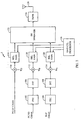
- FIG. 2 shows subscriber station 2 capable of transmitting multiple synchronous sub-channels in accordance with one embodiment of the invention.
- pilot, supplemental, and fundamental channel signals are produced for transmission on orthogonal sub-channels.
- the pilot channel is a known, constant transmitted waveform, and therefore carries no data. For this reason, forward error correction and interleaving are unnecessary on the pilot channel.
- the pilot channel is sent directly into a Walsh spreader 110 which spreads the data according to a pilot channel Walsh function W P , thus producing a Walsh covered pilot channel signal.
- the Walsh covered pilot channel signal is then sent to a relative gain module 116, which adjusts the amplitude of the covered pilot channel signal relative to the signals carried by other orthogonal transmit sub-channels.
- the pilot channel Walsh function is the all-zero Walsh code
- the pilot channel Walsh spreader 110 is omitted
- a DC signal is sent directly into relative gain module 116.
- the fundamental channel data is first sent to a forward error correction (FEC) encoder 102, which produces an encoded fundamental channel signal.
- FEC forward error correction
- the resultant encoded fundamental channel signal is sent to an interleaver 106, which produces an interleaved fundamental channel signal.
- the interleaved fundamental channel signal is then sent to the Walsh spreader 112, which spreads the data according to a fundamental channel Walsh function W F , thus producing a covered fundamental channel signal.
- the covered fundamental channel signal is then sent to a relative gain module 118, which adjusts the amplitude of the covered fundamental channel signal relative to the signals carried by other orthogonal transmit sub-channels.
- the supplemental channel data is first sent to a forward error correction (FEC) encoder 104, which produces an encoded supplemental channel signal.
- FEC forward error correction
- the resultant encoded supplemental channel signal is sent to an interleaver 108, which produces an interleaved supplemental channel signal.
- the interleaved supplemental channel signal is then sent to the Walsh spreader 114, which spreads the data according to a supplemental channel Walsh function W S , thus producing a covered supplemental channel signal.
- the covered supplemental channel signal is then sent to a relative gain module 120, which adjusts the amplitude of the covered supplemental channel signal relative to the signals carried by other orthogonal transmit sub-channels.
- the preferred embodiment shown uses orthogonal Walsh functions to accomplish sub-channel coding
- the sub-channel coding could also be accomplished using TDMA or PN coding without departing from the current invention.
- the reference signals W S , W P , and W F are replaced by PN codes corresponding to the supplemental, pilot, and fundamental channels respectively.
- the FEC modules 102 and 104 could employ any of a number of forward error correction techniques without departing from the current invention. Such techniques include turbo-code encoding, convolutional coding, or other forms of coding such as block coding.
- the interleavers 106 and 108 could utilize any of a number of interleaving techniques, including convolutional interleaving, turbo-interleaving, block interleaving and bit reversal interleaving. Turbo code encoders and turbo interleavers are described in aforementioned cdma2000 specification.
- each relative gain module 116, 118, and 120 is then sent to the PN spreader module 122.
- the output of the PN spreader module 122 is then sent to transmitter 124.
- Transmitter 124 provides additional control of transmit gain by varying the gain of the entire composite signal received from PN spreader module 122 before transmitting the signal through antenna 126.
- the optional relative gain module 116 is omitted, and the pilot signal is sent directly to the PN spreader module 122.
- the gains of other channels are adjusted with respect to the gain of the pilot channel.
- any sub-channel signal may be "turned off” by causing its effective transmit gain to equal zero. This may be accomplished by so configuring its respective relative gain module 116, 118, or 120. The same result may be obtained by discontinuing the progress of the sub-channel signal through the PN spreader, such as with a logic switch.
- One skilled in the art will appreciate that one may use either method of setting a sub-channel's effective transmit gain to zero without departing from the present invention.
- the PN spreader 122 spreads the orthogonal channel signals using a pseudorandom generated spreading sequence and sends the resultant composite signal to the transmitter 124 for transmission through the antenna 126.
- the PN spreader 122 utilizes complex PN spreading, as described in aforementioned U.S. Patent No. 5,926,500.
- the PN spreader 122 may additionally rotate the signals of the fundamental and supplemental channel outputs of gain modules 118 and 120 by 90 degrees relative to the pilot channel signal output by gain module 116 prior to performing PN spreading.
- PN spreader 122 could produce one complex spread signal for each input signal, allowing relative gain modules 116, 118, and 120, to be placed after PN spreader 122 and before transmitter 124 .
- the relative gains applied by relative gain modules 116, 118, and 120 are controlled dynamically by gain control processor 128.
- the gain of each module may be altered according to data rates of the channels. For example, the pilot channel gain may be increased when data is being transmitted on both the fundamental and the supplemental channel. Or, the fundamental channel gain may be increased when data is being transmitted on the supplemental channel.
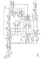
- FIG. 3 shows a preferred embodiment of the invention as used in a wireless receiver.
- the composite signal containing three orthogonal sub-channels is received through the antenna 200 and is downconverted in the receiver 202.
- the resultant downconverted signal is then sent to the complex PN despreader 204 to produce I and Q component samples used in subsequent processing.
- Complex PN despreader operates in accordance with aforementioned U.S. Patent No. 5,926,500.
- the operation of fundamental channel estimation apparatus 250, pilot channel estimation apparatus 252, and channel estimate combiner 230 are explained in detail below.
- the I and Q component samples are sent to a Walsh despreader 206, which uses the same Walsh function W F used to spread the fundamental channels in the Walsh spreader 112.
- the Walsh despreader 206 produces I and Q components for the decovered fundamental channel.
- pilot channel estimator 218a receives pilot I and Pilot Q samples from pilot channel estimator 218a, to produce filtered Pilot I and Pilot Q samples.
- Pilot channel estimator 218a is shown with an input of Walsh code W P , which corresponds to the W P used to spread the pilot channel in Walsh spreader 110.
- FIG. 4 shows an exemplary embodiment of a channel estimator 218.
- the complex input signal is provided to channel estimator 218 as I and Q sample streams.
- the I samples are mixed with a reference signal in mixer 302a, to extract a real component of the complex input signal.
- the output of mixer 302a is provided to noise rejection filter 304a to remove noise from the extracted real component.
- the Q samples are mixed with the same reference signal as used in mixer 302a in order to extract an imaginary component of the complex input signal.
- the output of mixer 302b is provided to noise rejection filter 304b to remove noise from the extracted imaginary component.
- the noise rejection filters 304 may be implemented as low-pass filters, matched filters, or accumulators without departing from the current invention.
- the reference signal used in a channel estimator 218 could be real, imaginary, or complex.
- mixers 302 are complex multipliers (which may also be called complex mixers), each having both real and imaginary outputs.
- the real outputs of mixers 302 are then summed before being filtered in real-component filter 304a.
- the imaginary outputs of mixers 302 are summed before being filtered in imaginary-component filter 304b.
- complex multipliers could be used in a Walsh spreader or despreader to allow the use of complex Walsh codes as reference functions during spreading and despreading. Walsh spreading using complex Walsh codes is known as complex Walsh spreading, and Walsh despreading using complex Walsh codes is known as complex Walsh despreading.
- the pilot channel is transmitted 90 degrees out of phase with the fundamental and supplemental channels.
- the pilot channel estimator 218a rotates its output by 90 degrees. This rotation may be accomplished in many ways, including multiplying the reference by an imaginary value, or by rotating the real and imaginary outputs of noise rejection filters 304. The same end result may also be accomplished by rotating the signals of the fundamental and supplemental channels without departing from the current invention. Also, the relative rotation of the pilot channel in relation to the fundamental and supplemental channels may be positive or negative without departing from the current invention.
- the extracted real and imaginary components constitute a channel estimate vector containing amplitude and phase information for any signal component which correlates with the reference signal.
- the quality of the channel estimate depends on the degree of correlation between the received complex input signal and the reference signal.
- the reference signal used by the receiver must exactly match that transmitted by the transmitter, for example Walsh code W P in the case of the pilot channel. Any difference between the reference signal and the transmitted signal can cause inaccuracy in the channel estimate.
- the pilot Walsh code W P is an all-zero Walsh code, in which case a channel estimate can be made using just a pair of filters, as is described in aforementioned U.S. Patent 5,506,865.
- pilot channel Walsh spreader 110 is omitted from the transmitter.
- the channel estimator in the receiver could then be implemented such that the mixers 302 could be omitted from pilot channel estimator 218a.
- a channel estimator for an all-zero Walsh code pilot consisting of filters without mixers, is also known as a pilot filter.
- pilot I and Pilot Q signals are used as an estimate of the amplitude and phase characteristics of the CDMA transmission channel 8.
- the resultant Pilot I and Pilot Q along with the decovered fundamental channel I and Q components are provided to dot product module 208.
- Dot product module 208 which computes the scalar projection of the fundamental channel signal onto the pilot channel estimate vector, in accordance with the circuit described in aforementioned U.S. Patent No. 5,506,865. Because the pilot channel signal 10, the fundamental channel signal 12, and the supplemental channel signal 14 have traversed the same propagation path 8, the channel induced phase error is the same for all three signals.
- the fundamental channel is coherently demodulated in a dot product module 208 using a pilot channel estimate.
- the dot product module produces a scalar signal for each symbol period, which is indicative of the magnitude of the fundamental channel signal that is in phase with the pilot signal received through the transmission channel 8.
- the fundamental channel symbols output by the dot product module 208 is then sent into deinterleaver 210, which performs the inverse of the function of transmit interleaver 106.
- the resultant deinterleaved signal is then sent to forward error correction (FEC) decoder 212.
- FEC forward error correction
- Decoder 212 performs the inverse function of the FEC encoder 102 and outputs a forward error corrected signal.
- the corrected signal output by decoder 212 is also sent to an encoder 224, which re-encodes the signal using the same FEC function as the transmitter FEC encoder 102.
- encoder 224 produces an ideal representation of the transmitted fundamental signal.
- This ideal representation is then sent to an interleaver 226, which performs the same function as the transmitter interleaver 106, producing an ideal representation of the interleaved fundamental channel data transmitted by subscriber station 2.
- the I and Q component samples produced by Walsh despreader 206 are also input into delays 220, which produce I and Q components which are synchronized with the output of the interleaver 226.
- Delays 220 are designed to compensate for the delays introduced by the dot product module 208, the deinterleaver 210, the decoder 212, the encoder 224, and the interleaver 226.
- Channel estimator 218b uses the output of interleaver 226 as a reference signal, and uses the outputs of delays 220 as the I and Q sample stream from which it forms a channel estimate output.
- the corrected bits output by FEC decoder 212 are re-encoded and re-interleaved to produce a reference signal which has a higher probability of matching what was actually transmitted on the fundamental channel.
- this more reliable reference signal as input for channel estimator 218b, the accuracy of fundamental channel estimates produced by channel estimator 218b is improved.
- the output of dot product module 208 could be provided directly to channel estimator 218b.
- delay elements 220 would only compensate for the time required to perform the dot product operation in dot product module 208.
- the fundamental channel estimator would not gain the error correction benefits of the bypassed components.
- the complex output components of the pilot channel estimator 218a are subjected to delay elements 222 to compensate for the delay inherent in performing channel estimation using the fundamental channel signal.
- the channel estimation parameters produced by processing of the fundamental channel is sent, along with the delayed channel estimation parameters from the delay elements 220 and 222 into channel estimate combiner 230.
- Channel estimate combiner 230 combines the channel estimation data for both pilot and fundamental channel processing and produces output containing a third, combined channel estimate.
- pilot channel estimator 218a and channel estimator 218b provide updated channel estimates to channel estimate combiner 230, which updates the combined channel estimation output accordingly.
- the output of decoder 212 sent to encoder 224 is additionally sent to control processor 216.
- Control processor 216 produces frame rate information for each received frame of data.
- Control processor 216 also performs validity checking of the received frames.
- Control processor 216 produces a fundamental channel quality metric based on the results of its rate determination and validity checking of received data.
- the fundamental channel quality metric is used to assign an appropriate weighting factor to the fundamental channel estimate in relation to the weighting factor assigned to the pilot channel estimate.
- the fundamental channel quality metric varies based on the validity of received frames based on the correctness of the CRC. Since different rate frames may also use different numbers of CRC bits, or have varying degrees of frame error checking protection, control processor 216 may additionally vary the fundamental channel quality metric according to received frame rate.
- Control processor 216 is also connected to encoder 224. Control processor 216 sends frame rate information to encoder 224 for use in re-encoding the data received from decoder 212.
- channel estimate combiner 230 is a weighted-average combiner, which produces the combined channel estimation signal by performing a weighted average of the pilot and fundamental channel estimates in accordance with the following equations:
- R COMB X R PILOT + (1-X)
- R FUND I COMB X I PILOT + (1-X) I FUND
- R COMB and I COMB are the real and imaginary components of the combined channel estimate
- R PILOT and I PILOT are the real and imaginary components of the pilot channel estimate
- R FUND and I FUND are the real and imaginary components of the fundamental channel estimate
- X is a scaling factor.
- the scaling factor X has a value from 0 to 1.
- a scaling factor value of 1 results in a combined channel estimate which is equal to the pilot channel estimate.
- a scaling factor value of 0 results in a combined channel estimate which is equal to the fundamental channel estimate.
- the value of X represents a first multiplier, which is multiplied by the pilot channel estimate to produce a scaled channel estimate for the pilot channel.
- the value of (I-X) represents a second multiplier, which is multiplied by the fundamental channel estimate to produce a scaled channel estimate for the fundamental channel. The two scaled channel estimates are added together to produce the combined channel estimate.
- Channel estimate combiner 230 additionally uses the fundamental channel quality metric provided by control processor 216 as a dynamic weighting factor to the channel estimates produced from the fundamental channel.
- the fundamental channel quality metric indicates a high rate of frame errors
- channel estimate combiner 230 increases the value of the scaling factor X.
- frame errors occur, therefore, the combined channel estimate used for demodulating the supplemental channel is derived more from the pilot channel estimate and less from the fundamental channel estimate.
- a frame error causes the value of scaling factor X to be equal to 1 until a valid frame is received.
- control processor 216 includes a smoothing module, which performs smoothing, or low-pass filtering, of the fundamental channel quality metric before it is sent to channel estimate combiner 230. This smoothing helps to make the weighted average performed by channel estimate combiner 230 less susceptible to high-frequency noise inherent in the channel.
- the receiver knows the relative gains used by relative gain modules 116 and 118 when transmitting the pilot and fundamental channel signals.
- the value of X is adjusted such that the ratio of the first multiplier over the second multiplier is equal to the ratio of the transmit gain of the pilot channel over the transmit gain of the fundamental channel.
- the fundamental channel quality metric provided by control processor 216 to channel estimate combiner 230 is synchronized with the reference signal provided to channel estimator 218b. This can be accomplished by incorporating a delay or buffer into control processor 216. Control processor 216 may also perform a smoothing function to the fundamental channel quality metric before providing it to channel estimator 218b. In the preferred embodiment, however, the fundamental channel quality metric produced by control processor 216 is not smoothed, and may change suddenly on frame boundaries.
- Walsh despreader 236 uses the Walsh function W S used by the transmitter's Walsh spreader 114, and produces decovered supplemental channel I and Q components. These decovered supplemental channel components, along with the combined channel estimation signal from channel estimate combiner 230, are used as inputs for dot product module 238.
- Dot product module 238 computes the magnitude of the projection of the supplemental channel signal onto the combined channel estimate vector, resulting in a scalar projection output.
- the output of dot product module 238 is then deinterleaved in deinterleaver 240, which performs the inverse function of interleaver 108.
- the output of deinterleaver 240 is provided to decoder 242, which performs the inverse function of interleaver 104.
- any of the delay elements 220, 222, or 232 could be implemented as accumulators or buffers without departing from the current invention.
- pairs of delay elements for example delay elements 232a and 232b, may be implemented separately, or combined into a single delay module which performs the same function, without departing from the current invention.
- reference signals W S , W P , and W F are replaced by PN codes corresponding to the supplemental, pilot, and fundamental channels respectively.
Landscapes
- Engineering & Computer Science (AREA)
- Computer Networks & Wireless Communication (AREA)
- Signal Processing (AREA)
- Power Engineering (AREA)
- Mobile Radio Communication Systems (AREA)
- Digital Transmission Methods That Use Modulated Carrier Waves (AREA)
- Optical Communication System (AREA)
- Measuring Pulse, Heart Rate, Blood Pressure Or Blood Flow (AREA)
- Noise Elimination (AREA)
- Error Detection And Correction (AREA)
- Monitoring And Testing Of Transmission In General (AREA)
- Cable Transmission Systems, Equalization Of Radio And Reduction Of Echo (AREA)
- Detection And Prevention Of Errors In Transmission (AREA)
- Circuits Of Receivers In General (AREA)
- Synchronisation In Digital Transmission Systems (AREA)
Applications Claiming Priority (3)
| Application Number | Priority Date | Filing Date | Title |
|---|---|---|---|
| US310232 | 1999-05-12 | ||
| US09/310,232 US6414988B1 (en) | 1999-05-12 | 1999-05-12 | Amplitude and phase estimation method in a wireless communication system |
| PCT/US2000/012792 WO2000070773A2 (en) | 1999-05-12 | 2000-05-10 | Amplitude and phase estimation method in a wireless communication system |
Publications (2)
| Publication Number | Publication Date |
|---|---|
| EP1177661A2 EP1177661A2 (en) | 2002-02-06 |
| EP1177661B1 true EP1177661B1 (en) | 2005-09-21 |
Family
ID=23201550
Family Applications (1)
| Application Number | Title | Priority Date | Filing Date |
|---|---|---|---|
| EP00930554A Expired - Lifetime EP1177661B1 (en) | 1999-05-12 | 2000-05-10 | Amplitude and phase estimation method in a wireless communication system |
Country Status (16)
| Country | Link |
|---|---|
| US (2) | US6414988B1 (enExample) |
| EP (1) | EP1177661B1 (enExample) |
| JP (3) | JP4777517B2 (enExample) |
| KR (1) | KR100780579B1 (enExample) |
| CN (1) | CN1233136C (enExample) |
| AT (1) | ATE305198T1 (enExample) |
| AU (1) | AU769552B2 (enExample) |
| BR (1) | BR0010421B1 (enExample) |
| CA (2) | CA2374282C (enExample) |
| DE (1) | DE60022750T2 (enExample) |
| IL (1) | IL146266A0 (enExample) |
| MX (1) | MXPA01011492A (enExample) |
| NO (1) | NO326935B1 (enExample) |
| RU (1) | RU2271068C2 (enExample) |
| UA (1) | UA64029C2 (enExample) |
| WO (1) | WO2000070773A2 (enExample) |
Cited By (1)
| Publication number | Priority date | Publication date | Assignee | Title |
|---|---|---|---|---|
| JP2003521840A (ja) * | 1999-05-12 | 2003-07-15 | クゥアルコム・インコーポレイテッド | 無線通信システムにおける振幅および位相の評価方法 |
Families Citing this family (72)
| Publication number | Priority date | Publication date | Assignee | Title |
|---|---|---|---|---|
| US6173007B1 (en) * | 1997-01-15 | 2001-01-09 | Qualcomm Inc. | High-data-rate supplemental channel for CDMA telecommunications system |
| JPH11261958A (ja) * | 1998-03-09 | 1999-09-24 | Sony Corp | 映像編集装置及び映像編集方法 |
| KR100450791B1 (ko) * | 1999-07-13 | 2004-10-01 | 삼성전자주식회사 | 씨디엠에이 복조방법 및 복조기 |
| JP3487842B2 (ja) * | 1999-07-15 | 2004-01-19 | インフィネオン テクノロジーズ アクチェンゲゼルシャフト | モバイル無線チャネルのチャネルインパルス応答を推定する方法 |
| US6785554B1 (en) * | 1999-09-15 | 2004-08-31 | Qualcomm Incorporated | Modified finger assignment algorithm for high data rate calls |
| US6831956B1 (en) | 1999-09-28 | 2004-12-14 | Texas Instruments Incorporated | Wireless communications system with combining of multiple paths selected from sub-windows in response to the primary synchronization channel |
| US6829290B1 (en) * | 1999-09-28 | 2004-12-07 | Texas Instruments Incorporated | Wireless communications system with combining of multiple paths selected from correlation to the primary synchronization channel |
| US6892053B2 (en) * | 1999-12-01 | 2005-05-10 | Telefonaktiebolaget Lm Ericsson (Publ) | Bit error estimates from pilot signals |
| US6975670B1 (en) * | 2000-10-02 | 2005-12-13 | Koninklijke Philips Electronics N.V. | Managing assigned fingers in wireless telecommunication using a finger lock mechanism |
| JP3286289B2 (ja) * | 1999-12-28 | 2002-05-27 | 松下電器産業株式会社 | Cdma受信装置及び誤り訂正方法 |
| AU2466001A (en) | 1999-12-30 | 2001-07-16 | Morphics Technology, Inc. | A configurable all-digital coherent demodulator system for spread spectrum applications |
| AU2001252897A1 (en) * | 2000-03-09 | 2001-09-17 | Raytheon Company | Frequency domain direct sequence spread spectrum with flexible time frequency code |
| US20090262700A1 (en) * | 2000-03-09 | 2009-10-22 | Franceschini Michael R | Frequency domain direct sequence spread spectrum with flexible time frequency code |
| US20040105382A1 (en) * | 2000-05-25 | 2004-06-03 | Kenichi Miyoshi | Radio reception apparatus |
| US6628702B1 (en) | 2000-06-14 | 2003-09-30 | Qualcomm, Incorporated | Method and apparatus for demodulating signals processed in a transmit diversity mode |
| AU2001297747A1 (en) * | 2000-10-27 | 2002-09-12 | L-3 Communications Corporation | Two-dimensional channel bonding in a hybrid cdma/fdma fixed wireless access system to provide finely variable rate channels |
| US7190683B2 (en) | 2000-10-27 | 2007-03-13 | L-3 Communications Corporation | Two-dimensional channel bonding in a hybrid CDMA/FDMA fixed wireless access system to provide finely variable rate channels |
| US6990153B1 (en) * | 2001-02-06 | 2006-01-24 | Agency For Science, Technology And Research | Method and apparatus for semi-blind communication channel estimation |
| JP4081526B2 (ja) * | 2001-03-26 | 2008-04-30 | クアルコム・インコーポレイテッド | 信号をサンプリングおよび/または再構成するためのサンプリング方法、再構成方法および機器 |
| JP3676986B2 (ja) * | 2001-03-29 | 2005-07-27 | 松下電器産業株式会社 | 無線受信装置及び無線受信方法 |
| US20050063487A1 (en) * | 2001-05-08 | 2005-03-24 | Soheil Sayegh | Method and apparatus for parameter estimation, modulation classification and interference characterization in satellite communication systems |
| DE60129111T2 (de) * | 2001-05-29 | 2008-02-28 | Lucent Technologies Inc. | Kanalschätzung in einem CDMA-System mit codierten Steuersymbolen als zusätzlichen Pilotsymbolen |
| JP3573745B2 (ja) * | 2001-07-13 | 2004-10-06 | 川崎マイクロエレクトロニクス株式会社 | Cdma受信装置およびcdma受信方法 |
| JP4448633B2 (ja) * | 2001-08-31 | 2010-04-14 | 富士通株式会社 | 移動体通信端末 |
| JP3831229B2 (ja) * | 2001-10-31 | 2006-10-11 | 富士通株式会社 | 伝搬路特性推定装置 |
| US6940894B2 (en) * | 2001-11-08 | 2005-09-06 | Qualcomm Incorporated | Power estimation using weighted sum of pilot and non-pilot symbols |
| US7133437B2 (en) | 2002-01-31 | 2006-11-07 | Qualcomm Incorporated | Pilot interpolation for a gated pilot with compensation for induced phase changes |
| US7221699B1 (en) * | 2002-06-28 | 2007-05-22 | Arraycomm Llc | External correction of errors between traffic and training in a wireless communications system |
| US7085582B2 (en) * | 2002-07-31 | 2006-08-01 | Motorola, Inc. | Pilot information gain control method and apparatus |
| US7239672B2 (en) * | 2002-09-05 | 2007-07-03 | Silicon Integrated Systems Corp. | Channel estimator for WLAN |
| US7254170B2 (en) * | 2002-11-06 | 2007-08-07 | Qualcomm Incorporated | Noise and channel estimation using low spreading factors |
| DE10306171B4 (de) * | 2003-02-13 | 2007-02-08 | Siemens Ag | Verfahren zum Einstellen der Sendeleistungen zweier Kanäle einer Verbindung, Station und Kommunikationssystem |
| US20040160922A1 (en) | 2003-02-18 | 2004-08-19 | Sanjiv Nanda | Method and apparatus for controlling data rate of a reverse link in a communication system |
| US8023950B2 (en) | 2003-02-18 | 2011-09-20 | Qualcomm Incorporated | Systems and methods for using selectable frame durations in a wireless communication system |
| US8391249B2 (en) | 2003-02-18 | 2013-03-05 | Qualcomm Incorporated | Code division multiplexing commands on a code division multiplexed channel |
| US7660282B2 (en) | 2003-02-18 | 2010-02-09 | Qualcomm Incorporated | Congestion control in a wireless data network |
| US7155236B2 (en) | 2003-02-18 | 2006-12-26 | Qualcomm Incorporated | Scheduled and autonomous transmission and acknowledgement |
| US7418064B2 (en) * | 2003-02-18 | 2008-08-26 | Qualcomm, Incorporated | Systems and methods for hierarchically demodulating and decoding a data signal using a pilot signal and an additional signal |
| US8150407B2 (en) | 2003-02-18 | 2012-04-03 | Qualcomm Incorporated | System and method for scheduling transmissions in a wireless communication system |
| US8081598B2 (en) | 2003-02-18 | 2011-12-20 | Qualcomm Incorporated | Outer-loop power control for wireless communication systems |
| US7216282B2 (en) * | 2003-02-19 | 2007-05-08 | Harris Corporation | Mobile ad-hoc network (MANET) including forward error correction (FEC), interleaving, and multi-route communication features and related methods |
| US8705588B2 (en) * | 2003-03-06 | 2014-04-22 | Qualcomm Incorporated | Systems and methods for using code space in spread-spectrum communications |
| US7215930B2 (en) | 2003-03-06 | 2007-05-08 | Qualcomm, Incorporated | Method and apparatus for providing uplink signal-to-noise ratio (SNR) estimation in a wireless communication |
| US8477592B2 (en) | 2003-05-14 | 2013-07-02 | Qualcomm Incorporated | Interference and noise estimation in an OFDM system |
| DE10328341B4 (de) * | 2003-06-24 | 2005-07-21 | Infineon Technologies Ag | Verfahren und Vorrichtung zur Berechnung von Korrekturfaktoren für Pfadgewichte in einem RAKE-Empfänger |
| US8489949B2 (en) | 2003-08-05 | 2013-07-16 | Qualcomm Incorporated | Combining grant, acknowledgement, and rate control commands |
| EP1668853B1 (en) * | 2003-09-30 | 2017-07-05 | Telecom Italia S.p.A. | Channel estimation using different types of pilot symbols |
| US20060059411A1 (en) * | 2004-09-16 | 2006-03-16 | Sony Corporation And Sony Electronics, Inc. | Method and system for increasing channel coding gain |
| US8144806B2 (en) * | 2004-09-27 | 2012-03-27 | Marvell International Ltd. | Device, system and method of I/Q mismatch correction |
| US7660568B2 (en) * | 2004-09-27 | 2010-02-09 | Alcatel-Lucent Usa Inc. | Method and apparatus for generating a channel estimate using a non-pilot portion of a signal |
| ES2340393T3 (es) | 2005-04-29 | 2010-06-02 | Sony Deutschland Gmbh | Dispositivo de recepcion y metodo de comunicacion para un sistema de comunicacion ofdm con una nueva estructura de preambulo. |
| US7797615B2 (en) | 2005-07-07 | 2010-09-14 | Acer Incorporated | Utilizing variable-length inputs in an inter-sequence permutation turbo code system |
| US20070011557A1 (en) * | 2005-07-07 | 2007-01-11 | Highdimension Ltd. | Inter-sequence permutation turbo code system and operation methods thereof |
| US8493942B2 (en) * | 2005-08-01 | 2013-07-23 | Qualcomm Incorporated | Interference cancellation in wireless communication |
| US8165186B2 (en) * | 2005-08-12 | 2012-04-24 | Qualcomm Incorporated | Channel estimation for wireless communication |
| US7729433B2 (en) * | 2006-03-07 | 2010-06-01 | Motorola, Inc. | Method and apparatus for hybrid CDM OFDMA wireless transmission |
| CN101170531B (zh) * | 2006-10-24 | 2012-01-18 | 北京大学 | 一种信道估计方法及相应的通信方法和系统 |
| EP2149219A2 (en) | 2007-04-19 | 2010-02-03 | InterDigital Technology Corporation | Method and apparatus for performing jrnso in fdd, tdd and mimo communications |
| US8000382B2 (en) * | 2008-01-04 | 2011-08-16 | Qualcomm Incorporated | I/Q imbalance estimation and correction in a communication system |
| US8094701B2 (en) * | 2008-01-31 | 2012-01-10 | Telefonaktiebolaget Lm Ericsson (Publ) | Channel estimation for high data rate transmission using multiple control channels |
| US20090310707A1 (en) * | 2008-06-17 | 2009-12-17 | Jung-Fu Cheng | Transmitter and method for transmitting soft pilot symbols in a digital communication system |
| CN102308501B (zh) * | 2009-02-04 | 2014-04-16 | 瑞典爱立信有限公司 | 移动无线电通信系统中的方法和装置 |
| US8565352B2 (en) | 2010-05-03 | 2013-10-22 | Telefonaktiebolaget L M Ericsson (Publ) | Digital IQ imbalance compensation for dual-carrier double conversion receiver |
| US8804881B2 (en) * | 2010-07-13 | 2014-08-12 | Qualcomm Incorporated | Data communication devices, methods, and systems |
| CN103379059B (zh) * | 2012-04-23 | 2018-09-14 | 马维尔国际有限公司 | Mmse的信道估计方法和装置 |
| US9142003B2 (en) * | 2012-06-10 | 2015-09-22 | Apple Inc. | Adaptive frame rate control |
| WO2015154274A1 (zh) * | 2014-04-10 | 2015-10-15 | 华为技术有限公司 | 信道估计装置和方法 |
| CN109416537B (zh) * | 2016-04-18 | 2023-02-28 | 荣布斯系统集团公司 | 使用两个频带与无人驾驶飞行器通信的系统 |
| US10797836B2 (en) * | 2017-12-31 | 2020-10-06 | Qualcomm Incorporated | Measurement of data streams comprising data and pilot channels |
| US10367595B1 (en) * | 2018-04-18 | 2019-07-30 | Huawei Technologies Co., Ltd. | Apparatus and receiver for receiving RF analog signals |
| CN113472712B (zh) * | 2021-06-30 | 2023-05-19 | 中铁二院工程集团有限责任公司 | 一种相位噪声抑制方法 |
| US20230217383A1 (en) * | 2022-01-06 | 2023-07-06 | Mediatek Singapore Pte. Ltd. | Data-aided ssb signal processing |
Family Cites Families (36)
| Publication number | Priority date | Publication date | Assignee | Title |
|---|---|---|---|---|
| US5555268A (en) | 1994-01-24 | 1996-09-10 | Fattouche; Michel | Multicode direct sequence spread spectrum |
| JP3018840B2 (ja) * | 1993-07-27 | 2000-03-13 | 三菱電機株式会社 | フェージング補償装置 |
| US5471497A (en) * | 1993-11-01 | 1995-11-28 | Zehavi; Ephraim | Method and apparatus for variable rate signal transmission in a spread spectrum communication system using coset coding |
| US5418813A (en) * | 1993-12-06 | 1995-05-23 | Motorola, Inc. | Method and apparatus for creating a composite waveform |
| ZA95797B (en) * | 1994-02-14 | 1996-06-20 | Qualcomm Inc | Dynamic sectorization in a spread spectrum communication system |
| US5671218A (en) | 1994-04-28 | 1997-09-23 | Lucent Technologies Inc. | Controlling power and access of wireless devices to base stations which use code division multiple access |
| EP0715440B1 (en) * | 1994-06-22 | 2004-06-16 | NTT DoCoMo, Inc. | Synchronous detector and synchronizing method for digital communication receiver |
| US6137840A (en) * | 1995-03-31 | 2000-10-24 | Qualcomm Incorporated | Method and apparatus for performing fast power control in a mobile communication system |
| US5978413A (en) * | 1995-08-28 | 1999-11-02 | Bender; Paul E. | Method and system for processing a plurality of multiple access transmissions |
| KR0159201B1 (ko) * | 1995-12-06 | 1998-12-01 | 양승택 | Cdma 시스템에서의 동기식 이중 채널 qpsk 변복조 장치 및 그 변복조방법 |
| FI962140A7 (fi) * | 1996-05-21 | 1997-11-22 | Nokia Corp | Menetelmä impulssivasteen estimoimiseksi sekä vastaanotin |
| US5930230A (en) * | 1996-05-28 | 1999-07-27 | Qualcomm Incorporated | High data rate CDMA wireless communication system |
| US5912931A (en) * | 1996-08-01 | 1999-06-15 | Nextel Communications | Method for multicarrier signal detection and parameter estimation in mobile radio communication channels |
| KR100201250B1 (ko) * | 1996-08-14 | 1999-06-15 | 하나로통신주식회사 | 동기 복조 방법 |
| JP3715382B2 (ja) * | 1996-08-16 | 2005-11-09 | 株式会社東芝 | 受信装置 |
| US5881056A (en) * | 1996-08-20 | 1999-03-09 | Lucent Technologies Inc. | Method and apparatus of a multi-code code division multiple access receiver having shared accumulator circuits |
| US6067292A (en) * | 1996-08-20 | 2000-05-23 | Lucent Technologies Inc | Pilot interference cancellation for a coherent wireless code division multiple access receiver |
| JP3001040B2 (ja) * | 1996-09-20 | 2000-01-17 | 日本電気株式会社 | Cdmaセルラーシステム用閉ループ送信機電力制御ユニット |
| US5889827A (en) | 1996-12-12 | 1999-03-30 | Ericsson Inc. | Method and apparatus for digital symbol detection using medium response estimates |
| JP3795984B2 (ja) * | 1996-12-20 | 2006-07-12 | 富士通株式会社 | 無線受信機 |
| JP3006679B2 (ja) * | 1997-01-16 | 2000-02-07 | 日本電気株式会社 | セルラー移動電話システム |
| EP0856955A3 (en) | 1997-01-29 | 2000-09-06 | YRP Mobile Telecommunications Key Technology Research Laboratories Co., Ltd. | CDMA power control system |
| US5991284A (en) * | 1997-02-13 | 1999-11-23 | Qualcomm Inc. | Subchannel control loop |
| US6480521B1 (en) * | 1997-03-26 | 2002-11-12 | Qualcomm Incorporated | Method and apparatus for transmitting high speed data in a spread spectrum communications system |
| JP3459866B2 (ja) * | 1997-04-22 | 2003-10-27 | 埼玉日本電気株式会社 | 符号分割多元接続方式の送信電力制御方法 |
| JP3628145B2 (ja) * | 1997-05-21 | 2005-03-09 | 松下電器産業株式会社 | 送信電力制御装置及び送信電力制御方法 |
| US6173162B1 (en) | 1997-06-16 | 2001-01-09 | Telefonaktiebolaget Lm Ericsson (Publ) | Multiple code channel power control in a radio communication system |
| US6393005B1 (en) | 1997-06-27 | 2002-05-21 | Nec Corporation | Method of controlling transmitting power of a base station in a CDMA mobile communication system |
| JPH11127208A (ja) * | 1997-10-24 | 1999-05-11 | Fujitsu Ltd | パイロットシンボル及び仮判定データシンボルを用いた同期検波方法及び移動体通信用受信装置及び干渉除去装置 |
| US6134260A (en) * | 1997-12-16 | 2000-10-17 | Ericsson Inc. | Method and apparatus for frequency acquisition and tracking for DS-SS CDMA receivers |
| JP4147438B2 (ja) * | 1998-09-04 | 2008-09-10 | 富士通株式会社 | 復調器 |
| US6931050B1 (en) * | 1998-12-03 | 2005-08-16 | Ericsson Inc. | Digital receivers and receiving methods that scale for relative strengths of traffic and pilot channels during soft handoff |
| KR100433910B1 (ko) * | 1999-02-13 | 2004-06-04 | 삼성전자주식회사 | 부호분할다중접속 통신시스템의 주파수간핸드오프를 위한 전력 |
| US6363102B1 (en) * | 1999-04-23 | 2002-03-26 | Qualcomm Incorporated | Method and apparatus for frequency offset correction |
| US6414988B1 (en) * | 1999-05-12 | 2002-07-02 | Qualcomm Incorporated | Amplitude and phase estimation method in a wireless communication system |
| US6493329B1 (en) * | 1999-08-23 | 2002-12-10 | Qualcomm Incorporated | Adaptive channel estimation in a wireless communication system |
-
1999
- 1999-05-12 US US09/310,232 patent/US6414988B1/en not_active Expired - Lifetime
-
2000
- 2000-05-10 DE DE60022750T patent/DE60022750T2/de not_active Expired - Lifetime
- 2000-05-10 CN CNB008074089A patent/CN1233136C/zh not_active Expired - Lifetime
- 2000-05-10 CA CA002374282A patent/CA2374282C/en not_active Expired - Lifetime
- 2000-05-10 KR KR1020017014374A patent/KR100780579B1/ko not_active Expired - Fee Related
- 2000-05-10 JP JP2000619114A patent/JP4777517B2/ja not_active Expired - Lifetime
- 2000-05-10 IL IL14626600A patent/IL146266A0/xx unknown
- 2000-05-10 WO PCT/US2000/012792 patent/WO2000070773A2/en not_active Ceased
- 2000-05-10 AT AT00930554T patent/ATE305198T1/de not_active IP Right Cessation
- 2000-05-10 AU AU48354/00A patent/AU769552B2/en not_active Ceased
- 2000-05-10 BR BRPI0010421-3A patent/BR0010421B1/pt not_active IP Right Cessation
- 2000-05-10 CA CA2638972A patent/CA2638972C/en not_active Expired - Lifetime
- 2000-05-10 MX MXPA01011492A patent/MXPA01011492A/es active IP Right Grant
- 2000-05-10 RU RU2001133464/09A patent/RU2271068C2/ru not_active IP Right Cessation
- 2000-05-10 EP EP00930554A patent/EP1177661B1/en not_active Expired - Lifetime
- 2000-10-05 UA UA2001117666A patent/UA64029C2/uk unknown
-
2001
- 2001-11-09 NO NO20015489A patent/NO326935B1/no not_active IP Right Cessation
-
2002
- 2002-04-30 US US10/136,997 patent/US6683907B2/en not_active Expired - Lifetime
-
2011
- 2011-03-16 JP JP2011057894A patent/JP5313282B2/ja not_active Expired - Lifetime
-
2013
- 2013-05-17 JP JP2013104951A patent/JP5698307B2/ja not_active Expired - Lifetime
Cited By (2)
| Publication number | Priority date | Publication date | Assignee | Title |
|---|---|---|---|---|
| JP2003521840A (ja) * | 1999-05-12 | 2003-07-15 | クゥアルコム・インコーポレイテッド | 無線通信システムにおける振幅および位相の評価方法 |
| JP4777517B2 (ja) * | 1999-05-12 | 2011-09-21 | クゥアルコム・インコーポレイテッド | 無線通信システムにおける振幅および位相の評価方法 |
Also Published As
Similar Documents
| Publication | Publication Date | Title |
|---|---|---|
| EP1177661B1 (en) | Amplitude and phase estimation method in a wireless communication system | |
| EP1166457B1 (en) | Channel estimation in a cdma wireless communication system | |
| EP0916190B1 (en) | Coherent signal processing for cdma communication system | |
| EP1279238B1 (en) | Cdma system which uses pre-rotation before transmission | |
| CN1136378A (zh) | 扩频通信系统中用于相干通信接收的方法和装置 | |
| KR100803014B1 (ko) | 무선 통신 시스템에서의 진폭 및 위상 추정 방법 | |
| US20050163200A1 (en) | Digital communication systems having decreased memory | |
| HK1060669B (en) | Method and device for performing demodulation of information signal | |
| CA2261141C (en) | Coherent signal processing for cdma communication system | |
| HK1020814B (en) | Coherent signal processing for cdma communication system |
Legal Events
| Date | Code | Title | Description |
|---|---|---|---|
| PUAI | Public reference made under article 153(3) epc to a published international application that has entered the european phase |
Free format text: ORIGINAL CODE: 0009012 |
|
| 17P | Request for examination filed |
Effective date: 20011205 |
|
| AK | Designated contracting states |
Kind code of ref document: A2 Designated state(s): AT BE CH CY DE DK ES FI FR GB GR IE IT LI LU MC NL PT SE |
|
| AX | Request for extension of the european patent |
Free format text: AL;LT;LV;MK;RO;SI |
|
| GRAP | Despatch of communication of intention to grant a patent |
Free format text: ORIGINAL CODE: EPIDOSNIGR1 |
|
| GRAS | Grant fee paid |
Free format text: ORIGINAL CODE: EPIDOSNIGR3 |
|
| GRAA | (expected) grant |
Free format text: ORIGINAL CODE: 0009210 |
|
| AK | Designated contracting states |
Kind code of ref document: B1 Designated state(s): AT BE CH CY DE DK ES FI FR GB GR IE IT LI LU MC NL PT SE |
|
| PG25 | Lapsed in a contracting state [announced via postgrant information from national office to epo] |
Ref country code: AT Free format text: LAPSE BECAUSE OF FAILURE TO SUBMIT A TRANSLATION OF THE DESCRIPTION OR TO PAY THE FEE WITHIN THE PRESCRIBED TIME-LIMIT Effective date: 20050921 Ref country code: CH Free format text: LAPSE BECAUSE OF FAILURE TO SUBMIT A TRANSLATION OF THE DESCRIPTION OR TO PAY THE FEE WITHIN THE PRESCRIBED TIME-LIMIT Effective date: 20050921 Ref country code: BE Free format text: LAPSE BECAUSE OF FAILURE TO SUBMIT A TRANSLATION OF THE DESCRIPTION OR TO PAY THE FEE WITHIN THE PRESCRIBED TIME-LIMIT Effective date: 20050921 Ref country code: LI Free format text: LAPSE BECAUSE OF FAILURE TO SUBMIT A TRANSLATION OF THE DESCRIPTION OR TO PAY THE FEE WITHIN THE PRESCRIBED TIME-LIMIT Effective date: 20050921 |
|
| REG | Reference to a national code |
Ref country code: GB Ref legal event code: FG4D |
|
| REG | Reference to a national code |
Ref country code: CH Ref legal event code: EP |
|
| REG | Reference to a national code |
Ref country code: IE Ref legal event code: FG4D |
|
| REF | Corresponds to: |
Ref document number: 60022750 Country of ref document: DE Date of ref document: 20051027 Kind code of ref document: P |
|
| PG25 | Lapsed in a contracting state [announced via postgrant information from national office to epo] |
Ref country code: DK Free format text: LAPSE BECAUSE OF FAILURE TO SUBMIT A TRANSLATION OF THE DESCRIPTION OR TO PAY THE FEE WITHIN THE PRESCRIBED TIME-LIMIT Effective date: 20051221 Ref country code: GR Free format text: LAPSE BECAUSE OF FAILURE TO SUBMIT A TRANSLATION OF THE DESCRIPTION OR TO PAY THE FEE WITHIN THE PRESCRIBED TIME-LIMIT Effective date: 20051221 |
|
| REG | Reference to a national code |
Ref country code: SE Ref legal event code: TRGR |
|
| PG25 | Lapsed in a contracting state [announced via postgrant information from national office to epo] |
Ref country code: ES Free format text: LAPSE BECAUSE OF FAILURE TO SUBMIT A TRANSLATION OF THE DESCRIPTION OR TO PAY THE FEE WITHIN THE PRESCRIBED TIME-LIMIT Effective date: 20060101 |
|
| REF | Corresponds to: |
Ref document number: 60022750 Country of ref document: DE Date of ref document: 20060202 Kind code of ref document: P |
|
| PG25 | Lapsed in a contracting state [announced via postgrant information from national office to epo] |
Ref country code: PT Free format text: LAPSE BECAUSE OF FAILURE TO SUBMIT A TRANSLATION OF THE DESCRIPTION OR TO PAY THE FEE WITHIN THE PRESCRIBED TIME-LIMIT Effective date: 20060221 |
|
| REG | Reference to a national code |
Ref country code: CH Ref legal event code: PL |
|
| PG25 | Lapsed in a contracting state [announced via postgrant information from national office to epo] |
Ref country code: MC Free format text: LAPSE BECAUSE OF NON-PAYMENT OF DUE FEES Effective date: 20060531 |
|
| ET | Fr: translation filed | ||
| PLBE | No opposition filed within time limit |
Free format text: ORIGINAL CODE: 0009261 |
|
| STAA | Information on the status of an ep patent application or granted ep patent |
Free format text: STATUS: NO OPPOSITION FILED WITHIN TIME LIMIT |
|
| 26N | No opposition filed |
Effective date: 20060622 |
|
| PG25 | Lapsed in a contracting state [announced via postgrant information from national office to epo] |
Ref country code: LU Free format text: LAPSE BECAUSE OF NON-PAYMENT OF DUE FEES Effective date: 20060510 |
|
| PG25 | Lapsed in a contracting state [announced via postgrant information from national office to epo] |
Ref country code: CY Free format text: LAPSE BECAUSE OF FAILURE TO SUBMIT A TRANSLATION OF THE DESCRIPTION OR TO PAY THE FEE WITHIN THE PRESCRIBED TIME-LIMIT Effective date: 20050921 |
|
| PGFP | Annual fee paid to national office [announced via postgrant information from national office to epo] |
Ref country code: FI Payment date: 20100503 Year of fee payment: 11 Ref country code: IE Payment date: 20100507 Year of fee payment: 11 |
|
| PGFP | Annual fee paid to national office [announced via postgrant information from national office to epo] |
Ref country code: NL Payment date: 20100510 Year of fee payment: 11 |
|
| PGFP | Annual fee paid to national office [announced via postgrant information from national office to epo] |
Ref country code: SE Payment date: 20100507 Year of fee payment: 11 |
|
| REG | Reference to a national code |
Ref country code: NL Ref legal event code: V1 Effective date: 20111201 |
|
| REG | Reference to a national code |
Ref country code: SE Ref legal event code: EUG |
|
| PG25 | Lapsed in a contracting state [announced via postgrant information from national office to epo] |
Ref country code: FI Free format text: LAPSE BECAUSE OF NON-PAYMENT OF DUE FEES Effective date: 20110510 Ref country code: NL Free format text: LAPSE BECAUSE OF NON-PAYMENT OF DUE FEES Effective date: 20111201 |
|
| REG | Reference to a national code |
Ref country code: IE Ref legal event code: MM4A |
|
| PG25 | Lapsed in a contracting state [announced via postgrant information from national office to epo] |
Ref country code: IE Free format text: LAPSE BECAUSE OF NON-PAYMENT OF DUE FEES Effective date: 20110510 |
|
| PG25 | Lapsed in a contracting state [announced via postgrant information from national office to epo] |
Ref country code: SE Free format text: LAPSE BECAUSE OF NON-PAYMENT OF DUE FEES Effective date: 20110511 |
|
| REG | Reference to a national code |
Ref country code: FR Ref legal event code: PLFP Year of fee payment: 17 |
|
| REG | Reference to a national code |
Ref country code: FR Ref legal event code: PLFP Year of fee payment: 18 |
|
| REG | Reference to a national code |
Ref country code: DE Ref legal event code: R082 Ref document number: 60022750 Country of ref document: DE Representative=s name: MAUCHER JENKINS, DE Ref country code: DE Ref legal event code: R082 Ref document number: 60022750 Country of ref document: DE Representative=s name: MAUCHER JENKINS PATENTANWAELTE & RECHTSANWAELT, DE |
|
| REG | Reference to a national code |
Ref country code: FR Ref legal event code: PLFP Year of fee payment: 19 |
|
| PGFP | Annual fee paid to national office [announced via postgrant information from national office to epo] |
Ref country code: IT Payment date: 20180522 Year of fee payment: 19 Ref country code: FR Payment date: 20180416 Year of fee payment: 19 |
|
| PGFP | Annual fee paid to national office [announced via postgrant information from national office to epo] |
Ref country code: DE Payment date: 20190412 Year of fee payment: 20 |
|
| PGFP | Annual fee paid to national office [announced via postgrant information from national office to epo] |
Ref country code: GB Payment date: 20190430 Year of fee payment: 20 |
|
| PG25 | Lapsed in a contracting state [announced via postgrant information from national office to epo] |
Ref country code: IT Free format text: LAPSE BECAUSE OF NON-PAYMENT OF DUE FEES Effective date: 20190510 |
|
| REG | Reference to a national code |
Ref country code: DE Ref legal event code: R071 Ref document number: 60022750 Country of ref document: DE |
|
| REG | Reference to a national code |
Ref country code: GB Ref legal event code: PE20 Expiry date: 20200509 |
|
| PG25 | Lapsed in a contracting state [announced via postgrant information from national office to epo] |
Ref country code: FR Free format text: LAPSE BECAUSE OF NON-PAYMENT OF DUE FEES Effective date: 20190531 |
|
| PG25 | Lapsed in a contracting state [announced via postgrant information from national office to epo] |
Ref country code: GB Free format text: LAPSE BECAUSE OF EXPIRATION OF PROTECTION Effective date: 20200509 |