US6975670B1 - Managing assigned fingers in wireless telecommunication using a finger lock mechanism - Google Patents
Managing assigned fingers in wireless telecommunication using a finger lock mechanism Download PDFInfo
- Publication number
- US6975670B1 US6975670B1 US09/678,472 US67847200A US6975670B1 US 6975670 B1 US6975670 B1 US 6975670B1 US 67847200 A US67847200 A US 67847200A US 6975670 B1 US6975670 B1 US 6975670B1
- Authority
- US
- United States
- Prior art keywords
- signal
- finger assignment
- strength
- threshold
- finger
- Prior art date
- Legal status (The legal status is an assumption and is not a legal conclusion. Google has not performed a legal analysis and makes no representation as to the accuracy of the status listed.)
- Expired - Lifetime, expires
Links
Images


Classifications
-
- H—ELECTRICITY
- H04—ELECTRIC COMMUNICATION TECHNIQUE
- H04B—TRANSMISSION
- H04B1/00—Details of transmission systems, not covered by a single one of groups H04B3/00 - H04B13/00; Details of transmission systems not characterised by the medium used for transmission
- H04B1/69—Spread spectrum techniques
- H04B1/707—Spread spectrum techniques using direct sequence modulation
- H04B1/7097—Interference-related aspects
- H04B1/711—Interference-related aspects the interference being multi-path interference
- H04B1/7115—Constructive combining of multi-path signals, i.e. RAKE receivers
- H04B1/7117—Selection, re-selection, allocation or re-allocation of paths to fingers, e.g. timing offset control of allocated fingers
-
- H—ELECTRICITY
- H04—ELECTRIC COMMUNICATION TECHNIQUE
- H04B—TRANSMISSION
- H04B1/00—Details of transmission systems, not covered by a single one of groups H04B3/00 - H04B13/00; Details of transmission systems not characterised by the medium used for transmission
- H04B1/69—Spread spectrum techniques
- H04B1/707—Spread spectrum techniques using direct sequence modulation
- H04B1/7097—Interference-related aspects
- H04B1/711—Interference-related aspects the interference being multi-path interference
- H04B1/7115—Constructive combining of multi-path signals, i.e. RAKE receivers
- H04B1/712—Weighting of fingers for combining, e.g. amplitude control or phase rotation using an inner loop
Definitions
- the present claimed invention relates to the field of wireless communication. Specifically, the present claimed invention relates to an apparatus and a method for managing assigned fingers in wireless communication device by using a finger lock mechanism.
- Wireless telephony e.g. cellular phone use
- Variable rate communication systems such as Code Division Multiple Access (CDMA) spread spectrum systems
- CDMA Code Division Multiple Access
- IS-95 Industry Standard
- a conventional base station 104 transmits a signal to a mobile unit 102 , e.g., a cell phone.
- the signal contains pilot information, that identifies the base station, and data information, such as voice content.
- first signal 106 a which provides the strongest signal.
- Corruption of a transmitted signal falls into two general categories: slowly-varying channel impairment and fast fading variation.
- Slowly-varying channel impairment arises from factors such as log-normal fading, or shadowing caused by movement or blocking from objects, as shown in prior art FIG. 1A , or from slow fading.
- Slower variations e.g., sub Hz, determine in effect, the “availability” of the channel.
- only the fast fading variation affects the details of the received waveform structure and the interrelationships of errors within a message.
- Interference on a signal can be caused by moving objects that temporarily block the signal, such as moving object 113 that interferes with signal 106 b of prior art FIG. 1 A. Based upon the characteristic differences of these signals, a need arises for a method of capturing a signal while avoiding the detrimental characteristics of fast fading or short fading variation encountered at the receiving unit.
- FIG. 1B a graph of the signal strength of two conventional multipath signals over time is shown. These curves are provided to illustrate how a conventional demodulation finger would react to fading signals.
- Graphs 100 b and 101 b illustrate some weaknesses of the conventional method of managing assigned fingers. These weaknesses will be more specifically described in a following figure, prior art FIG. 1 C.
- Graphs 100 b and 101 b have an abscissa 122 of time and an ordinate 120 of signal strength, e.g., signal-to-noise ratio (SNR).
- SNR can be a received pilot energy per chip, E c , divided by a total received spectral density (noise and signal), I o , thus yielding an Ec/Io ratio.
- Third multipath signal 106 c in graph 100 b and second multipath signal 106 b in graph 101 b are shown as exemplary multipath signals received at mobile unit 102 .
- Third multipath signal 106 c exceeds threshold 126 early in time, e.g., as shown where solid line changes to dashed line.
- third multipath signal 106 c fails to meet threshold 126 .
- third multipath signal 106 c regains its signal-strength value and exceeds threshold 126 .
- second multipath signal 106 b shown in graph 101 b , only satisfies threshold 126 after time 122 b . Even then, second multipath signal 106 b falls below threshold 126 shortly thereafter, at time 122 c . Both signals 106 b and 106 c show fast fading variation, which is caused by interfering object 113 in the case of signal 106 b , as shown in prior art FIG. 1 A. Second multipath signal 106 b would be deassigned 123 when it's signal-strength fell below threshold 126 , then reassigned 124 when it rose back above threshold 126 . This condition of continuously assigning, deassigning, and reassigning, at a high frequency is known as thrashing.
- Flowchart 100 c begins with step 1002 .
- an inquiry determines whether an assigned signal fails to meet a threshold for combining. If an assigned signal does fail to the single threshold, then flowchart 100 c ends. If the assigned signal satisfies the threshold, then flowchart 100 c ends.
- the finger assignment is immediately deassigned, e.g. because it failed to meet the threshold.
- flowchart proceeds to step 1006 .
- the communication device waits for the searcher to assign a new finger.
- Prior art FIG. 1C presents several problems associated with the conventional management of assigned fingers.
- the first problem deals with thrashing.
- the second problem deals with unnecessary latency.
- step 1002 the only criteria by which fingers are deassigned is a single threshold for combining the signal. This single threshold is shown in prior art FIG. 1B as threshold 126 .
- third multipath signal 106 c is immediately deassigned, per step 1004 , as soon as it fails threshold 126 , e.g., at time 122 a .
- one of the demodulating fingers must now wait for the searcher to identify a new multipath signal to be assigned, e.g., per step 1006 .
- This latency is shown as the delay 128 between time 122 a and 122 b , where third pilot 106 c is deassigned and second multipath signal 106 b is assigned.
- This latency caused by reassignment, appears to be unnecessary in the case presented in prior art FIG. 1 B.
- third multipath 106 c returns back to a satisfactory SNR level shortly after deassignment at time 122 a , e.g., which is typical performance for short fade performance.
- second multipath signal 106 b substituted for third multipath signal 106 c , appears to be an inferior candidate because it fails the threshold more frequently over time.
- the latency may have an adverse effect on the quality of the signal presented by mobile unit 102 to a user, especially if it occurs frequently or unnecessarily. Hence, a need arises to prevent the problem of latency caused by frequent or unnecessary changes in finger assignment.
- second multipath signal 106 b may be constantly assigned and deassigned from the given demodulating finger based on its performance. That is, second multipath signal 106 b frequently crosses the threshold value, thereby causing the communication device to frequently assign, deassign, and reassign a multipath signal to a demodulating finger that has no other worthy candidate multipath signals.
- This phenomenon of frequent assigning and deassigning is referred to as “thrashing.”
- thrashing consumes a significant amount of system resources, such as CPU operations, by constantly performing tasks such as assigning and deassigning.
- thrashing may downgrade the quality of the output signal from the mobile unit 102 . This is because the frequent changes in finger assignment, and its associated latency effects, may cause a perceptible degradation in the composite signal provided by the communication device to a user. Consequently, a need arises for a method of managing assigned fingers that avoids the problem of thrashing, and its associated side-effects.
- an apparatus and a method are needed to improve the capacity, fidelity, and performance of digital communication.
- a need arises to improve the power and the SNR of the signal captured at the mobile unit. That is, a need arises for a method of capturing a signal while avoiding the detrimental characteristics of fast fading variation encountered at the receiving unit.
- a need arises to prevent the problem of latency caused by frequent or unnecessary changes in finger assignment.
- a need arises for a method of managing assigned fingers that avoids the problem of thrashing.
- the present invention provides a method and apparatus for improving the capacity, fidelity, and performance of digital communication. More specifically, the present invention provides a method that improves the power and the SNR of the signal received at mobile unit. The present invention provides a method of capturing a signal while avoiding the detrimental characteristics of fast fading variation encountered at the receiving unit. In particular, the present invention avoids the problem of latency caused by frequent or unnecessary changes in finger assignment. Finally, the present invention implements the aforementioned method without the detrimental effects of thrashing.
- the present invention recites a method for managing assigned fingers in Code Division Multiple Access (CDMA) telecommunication system using a finger lock algorithm.
- the method includes a series of steps, including a first step of receiving a finger assignment from a searcher portion of a communication device.
- the signal-strength of the finger assignment is determined and filtered.
- a time period over which the signal-strength exists is determined.
- the finger assignment can then be compared to one or more signal-strength thresholds and/or to a time threshold.
- the finger assignment is evaluated for a combine operation based upon which of the aforementioned thresholds it satiates.
- the last two steps of comparing and evaluating the finger assignment include several additional steps.
- the finger assignment is enabled for combining if is a new finger assignment or if it continues to satiate a “combine” signal-strength threshold.
- the finger assignment is not enabled for combining, but neither is it deassigned (e.g., a locked state), if it fails to satiate the combine signal-strength threshold but does satiate a “lock” signal-strength threshold without exceeding a “time” threshold.
- control of the finger assignment is passed back to the searcher if the finger assignment fails to satiate the lock signal-strength threshold or the time threshold.
- the present invention provides a method of managing assigned fingers that avoids thrashing and latency effects of unnecessary switching.
- the multiple signal-strength thresholds and the time threshold essentially provide a buffer of signal-strength and of time, to account for short fading signals that can quickly recover their signal-strength.
- buffer essentially dampens an otherwise over-responsive conventional system.
- the present invention recites a communication device including a transceiver, a processor, and a computer readable memory, all coupled to each other.
- the memory portion of the communication device contains data and program instructions that, when executed via the processor, implement the aforementioned method for managing assigned fingers in a communication device.
- FIG. 1A is an illustration of multipath signal propagation between a conventional base station and a conventional mobile unit.
- FIG. 1B is graph of the signal strength of two conventional multipath signal-strengths over time.
- FIG. 1C is a flowchart of a conventional process used for implementing fingers in a communication device.
- FIG. 2 is a block diagram of the management functions performed on a finger assignment in a communication device, in accordance with one embodiment of the present invention.
- FIG. 3 is a block diagram of a communication device used for finger lock management of assigned fingers, in accordance with one embodiment of the present invention.
- FIG. 4 is a graph of the performance of one assigned finger over time as compared with multiple performance thresholds, in accordance with one embodiment of the present invention.
- FIG. 5A is a state diagram of finger locking states into which a finger assignment can be categorized, in accordance with one embodiment of the present invention.
- FIG. 5B is a state diagram of timing states into which a finger assignment can be categorized, in accordance with one embodiment of the present invention.
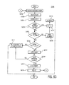
- FIG. 5C is a flowchart of a process for implementing the state diagrams for finger locking states and for timing states in a communication device, in accordance with one embodiment of the present invention
- FIG. 6 is a flowchart of a process used for finger lock management of assigned fingers in a communication device, in accordance with one embodiment of the present invention.
- Block diagram 200 receives signal 240 , transmitted from another device, e.g., base station 104 .
- SMC Block 242 Set Maintenance Central processing unit software
- SMC block 242 functions are well-known in the art.
- Demodulating block 243 is coupled to SMC block 242 .
- Demodulating block 243 performs the function of demodulating multipath signals using multiple demodulating fingers.
- the quantity of fingers used can vary widely, with the specific quantity of fingers upon a specific application goal and its available resources.
- CHEST block 244 is coupled to demodulating block 243 .
- CHEST block 244 provides a signal strength indication of a finger assignment.
- CHEST block 244 is a new function that is separate from the channel estimator function performed by SMC block 242 .
- CHEST block 244 performs dedicated channel estimation, and a more refined and accurate filtering operation, for a given multipath signal of the assigned finger.
- CHEST block 244 determines the E c /I o ratio (e.g. received pilot energy per chip, E c , divided by total received spectral density, I o ) and provides it, or a finger quality indicator (FQI), as output data 245 to the next block.
- E c /I o ratio e.g. received pilot energy per chip, E c , divided by total received spectral density, I o
- FQI finger quality indicator
- CHEST block 244 can use channel estimation data that was performed in the SMC block 242 , and simply perform an additional filtering operation on that data.
- Channel estimators include functions that are well-known in the art for performing signal-strength calculations.
- the CHEST block performs functions such as quadrature despreading, a sum and dump function, and an infinite impulse response (IIR) filter function.
- the IIR filter can have appropriate coefficients, e.g., forgetting factors, specifically determined for a specific application, given its performance goals and available resources.
- Finger lock block 246 is coupled to demodulating block 243 , which receives the FQI data 245 . Finger lock block 246 performs a logic function that interprets the E c /I o data 245 received from CHEST block 244 and/or timer data 251 received from timer block 249 . Finger lock block evaluates signal strength data 245 and timer data 251 against appropriate signal-strength thresholds and/or time thresholds to decide whether the multipath signal should be deassigned, locked, or subsequently combined. Details on the quantity, type, and values of thresholds is described in more detail in subsequent figures. Finger lock block 246 provides a finger combine indicator (FCI) output data 247 to the next block to which it is coupled, e.g., the combiner block 248 .
- FCI finger combine indicator
- Combiner block 248 combines, if directed by the FCI data 247 from finger lock block 246 , multipath signals that were demodulated by the assigned fingers. If FCI data indicates that a multipath signal demodulated by a finger assignment should not be combined, then combiner block 248 does not combine it. Alternatively, if FCI data from finger lock block 246 indicates that a multipath signal demodulated by a finger assignment should be combined, then combiner block 248 does combine it. Combiner block 248 provides composite signal output 250 that is decoded by subsequent function blocks that are not shown, but are well known in the art.
- the present invention provides an accurate and efficient buffer for holding assigned fingers during short-term fading.
- the prior art would drop finger assignments during short term fading, and reassign them when they recovered, thus causing the undesirable effect of thrashing.
- Communication device 300 e.g., a mobile or base unit, includes two general sections: firmware/software 310 and dedicated hardware 320 .
- Firmware/software section 310 includes processor 314 and memory 316 , coupled to each other via bus 302 .
- Firmware/software section 310 can be a general purpose device, or a specialized digital signal processing (DSP) device. Alternatively, the functions performed by firmware/software section 310 can be implemented using a specialized state machine.
- DSP digital signal processing
- Hardware section 320 of FIG. 3 includes an antennae 303 , a transceiver 304 , and a rake receiver 326 .
- Hardware section 320 is coupled to firmware/software portion 310 of communication device 310 to provide the raw data with which the firmware/software section can digitally process.
- Antennae 303 is coupled to transceiver 304 , which is in turn coupled to rake receiver 326 .
- Bus 302 provides an exemplary coupling configuration of devices in communication system 300 .
- Bus 302 is shown as a single bus line for clarity. It is appreciated by those skilled in the art that bus 302 can include subcomponents of specific data lines and/or control lines for the communication of commands and data between appropriate devices. It is further appreciated by those skilled in the art that bus 302 can include numerous gateways, interconnects, and translators, as appropriate for a given application.
- rake receiver 326 includes three fingers, e.g. finger 1 321 , finger 2 322 , and finger 3 323 .
- the present invention is well-suited to using any quantity of fingers in rake receiver 326 .
- Each finger 321 - 323 is coupled to transceiver 304 so that it may independently identify and demodulate its respective muitipath signal.
- the present invention provides efficient and flexible management of finger assignments for multipath signals, as described more fully hereinafter.
- Transceiver 304 , processor 314 , and memory 316 of FIG. 3 perform functions of SMC block 242 of FIG. 2 , in one embodiment.
- functions performed by demodulation block 243 , channel estimator block 244 , finger lock block 246 , timer block 249 , and combiner block 248 of FIG. 2 can be implemented by rake receiver 326 , processor 314 , and/or memory 316 of FIG. 3 , in one embodiment.
- communication system 300 is exemplary only and that the present invention can operate within a number of different communication systems. Furthermore, the present invention is well-suited to using a host of intelligent devices that have similar components as exemplary communication system 300 .
- FIG. 4 a graph of the performance of one assigned finger over time as compared with multiple performance thresholds is shown, in accordance with one embodiment of the present invention. Subsequent figures will utilize this performance curve as an example to illustrate the functions and the present invention's processes, e.g. managing assigned fingers.
- Graph 400 has an abscissa of time 422 and an ordinate of signal-strength 420 .
- Signal-strength can represent absolute signal power or some version of signal to noise ratio (SNR) such as E c /I c , described hereinabove.
- Second multipath signal 106 b is shown as an exemplary signal charted over a period of time.
- Graph 400 illustrates multiple thresholds used in the present invention.
- a first signal-strength threshold, Threshold Combine (T_COMB) 426 represents the threshold by which the management process of the present invention approves a finger assignment for a subsequent combine operation.
- the present embodiment also includes a second signal-strength threshold of Threshold Lock (T_LOCK) 428 .
- T_LOCK 428 has a lower value than T_COMB 426 .
- T_LOCK threshold 428 represents the threshold by which the management process of the present invention decides whether to lock or deassign a finger assignment.
- the third, and final, threshold is a time threshold, N_LOCk 424 , which relates to the amount of time that a multipath signal exists between the T_COMB 426 and T_LOCK 428 thresholds. While the present embodiment provides all three thresholds for evaluating the status of a multipath signal of a finger assignment (e.g. for a subsequent combine or deassign operation), the present invention is also suitable to using less than all three thresholds.
- the specific values T_LOCK 428 , T_COMB 426 , N_LOCK 424 can span a wide range of values, which are chosen depending upon requirements and assumptions for the specific application, hardware, and/or protocol used for a communication system.
- timespan 9 449 , timespan 4 444 , timespan 5 445 , and timespan 7 447 show performances of second multipath signal 106 b that exceed T_COMB threshold 426 .
- timespan 6 446 shows a performance of second multipath signal 106 b that fail to satiate T_COMB threshold 428 .
- timespan 1 441 , and timespan 10 450 show performances of second multipath signal 106 b that exceed T_COMB threshold 426 .
- Multiple system cycles can occur over any of the time spans listed in FIG. 4 . Subsequent figures will refer to these specific timespan to illustrate the states and the processes of the present invention management of finger assignments.
- State diagram 500 a shows the virtual interaction between the states in which a finger assignment may be categorized and managed by the present invention.
- State diagram 500 a will be used in subsequent figures to explain how the processes and equipment of the present invention effectively categorize and transition multipath signal finger assignments in these states.
- the thresholds referred to in FIG. 5A will be referenced to specific timespans of exemplary signal in FIG. 4 so as to provide explicit examples of state categorization and state transitions.
- State diagram 500 a of FIG. 5A shows states available for a multipath signal, as decided and provided by SMC (Set Maintenance Central processing unit (CPU)) software, e.g. by SMC block 242 of FIG. 2 described hereinabove.
- Multipath signals can have either of two states provided by SMC block 242 in FIG. 5 A.
- the first state is an assigned state 502 , having a prerequisite condition that the pilot portion of the multipath signal have a signal-strength, e.g. E c /I o , that is greater than (>) the threshold for adding (T_ADD).
- the T_ADD threshold used by a searcher is well-known in the art; its description is omitted herein for purposes of clarity. In the present embodiment, T_ADD has a lower value than either T_LOCK or T_COMB.
- the second state provided by the SMC block 242 of FIG. 5A is a deassign state 504 .
- One condition for maintaining a multipath signal, previously categorized in deassigned state 504 , in the deassigned state 504 is when the pilot portion of the multipath signal has a signal-strength, e.g. E c /I o , that is less than ( ⁇ ) the threshold for adding (T_ADD).
- Multipath signals categorized in locked state 506 or combined state 508 can be degraded into deassigned state 504 , as described hereinafter.
- Finger lock function block 246 also provides multiple states for a multipath signal as shown in state diagram 500 a .
- the present embodiment shows that two states exist in finger lock function block 246 .
- the first state is a combined state 508 .
- One condition by which a multipath signal can be categorized in combined state 508 is via an initial condition 550 .
- Initial condition 550 occurs when multipath signal is initially assigned, by SMC block 242 , e.g. the multipath signal in question was not in a combined or locked state in the immediately preceding cycle of the management process.
- the FQI e.g. E c /I o , does not necessarily need to satisfy T_LOCK or T_COMB thresholds, though it likely will.
- Timespan 9 449 of FIG. 4 illustrates this state change scenario, where it is assumed that multipath signal 106 d has just been acquired by searcher in timespan 9 449 .
- Timespan 4 444 of FIG. 4 also illustrates the state change scenario, where second multipath signal 106 b has been deassigned by SMC block 242 at timespan 6 446 , and thus appears as a new multipath signal assignment from SMC block 242 .
- upgrade condition 558 occurs when a multipath signal previously categorized in the locked state 506 has a finger quality indicator (FQI) that exceeds (>) T_COMB threshold.
- FQI finger quality indicator
- Timespan 7 447 of FIG. 4 illustrates this state transition scenario where multipath signal 106 b is in a locked state because its FQI>T_LOCK threshold, but its timespan at this FQI is less than the N_LOCK threshold.
- One condition that allows a multipath signal to remain categorized in combined state 508 is a maintain condition 552 , whose criteria is that the FQI of the multipath signal is greater than T_COMB threshold. Timespan 5 445 of FIG. 4 illustrates this state scenario.
- a multipath signal categorized in combine state 508 is provided for a subsequent combine operation 556 .
- the finger combine indicator (FCI) is set to one (1) to represent a state that the multipath signal can be combined in a subsequent combine operation.
- the FCI can represent an actual binary bit that can be a set or clear flag in a digital logic circuit or in software.
- the second state in finger lock function 246 is a locked state 506 .
- One condition by which a multipath signal may enter lock state 506 is downgrade condition 562 previously described.
- a multipath signal previously categorized in combined state 508 can be downgraded to a locked state 506 by downgrade condition 562 .
- Downgrade condition 562 occurs if multipath signal has FQI that is less than T_COMB but greater than T_LOCK. Timespan 1 441 of FIG. 4 illustrates this state change scenario.
- a multipath signal previously categorized in combined state 508 can be downgraded to the SMC function block 242 , where it can be categorized in deassigned state 504 by downgrade condition 566 .
- Downgrade condition 566 occurs if multipath signal has FQI that is less than T_LOCK for any period of time. Timespan 6 446 of FIG. 4 illustrates this state change scenario.
- Maintain condition 560 occurs for a multipath signal, previously categorized in locked state 506 , whose FQI is less than T_COMB but greater than T_LOCK threshold, and whose timer has not exceeded time threshold, TL (e.g., TL is greater than zero for a countdown timer configuration).
- Timespan 10 450 of FIG. 4 illustrates this locked state scenario because its timespan is not greater than N_LOCK 424 , by visual observation.
- the recovery of signal 106 b from timespan 10 illustrates a short-fade condition that did not create thrashing in a communication system because of the present invention's finger assignment management system.
- a multipath signal previously categorized in locked condition 506 is downgraded from locked condition 506 if it fails to satiate conditions for the lock state 506 .
- first downgrade condition 564 a occurs if multipath signal has a FQI that is less than T_COMB threshold and greater than T_LOCK threshold, but whose timer has exceeded the time threshold, TL (e.g., timespan 2 442 of FIG. 4 illustrates this state change scenario because its timespan exceeds N_LOCK 424 threshold by visual observation).
- Second downgrade condition 564 b occurs if multipath signal has a FQI that is less than T_LOCK threshold. Timespan 6 446 of FIG.
- SMC 4 illustrates this state scenario, assuming it was categorized in lock state 506 at least once between timespan 9 449 and timespan 6 446 .
- control of the finger is passed to SMC function 242 .
- SMC can perform any function or state categorizing of multipath signal, such as categorizing it in deassigned state 504 , where it will remain so long as the pilot E c /I o is less than T_ADD.
- Multipath signals categorized in locked state 506 are monitored by a timer, activated upon initial categorization into this state. Additionally, multipath signals categorized in locked state 506 have FCI set to zero (0) so that the multipath signal in question is not available for the subsequent combine operation. In one embodiment, each multipath signal finger assignment is independent of other multipath signal finger assignments. As such, more than one multipath signal can occupy any one of the states presented in FIG. 5 A. While the present embodiment of FIG. 5A provides specific requirements for categorizing a multipath signal into a state, and for a transition between states, the present invention is well-suited to using alternative thresholds or conditions.
- State diagram 500 b of FIG. 5B works in coordination with state diagram 500 a of FIG. 5A , to provide the timer state portion of the conditions required for the state categorization and to provide the combine state changes of a multipath signal to satisfy the finger management process of the present invention, as described more fully in subsequent figures.
- Timing diagram 500 b includes two states, a preload state 570 and a count-down state 572 .
- the present embodiment utilizes a count-down timer.
- the timer function can be accommodated by a count-up timer that is compared against a threshold, with appropriate indicating logic.
- the timer function can be implemented by hardware, such as timer block 328 of FIG. 3 .
- Preload state 570 sets the time threshold, TL, to N_LOCK 424 , shown in FIG. 4 . If the multipath signal does not enter a locked state, then it remains unlocked, per maintain condition 573 . However, if multipath signal changes to a locked state, then the timer changes states per condition 574 . The timer state can return from the countdown state 572 to preload state 570 if multipath signal becomes unlocked, per condition 578 .
- Countdown timer state 572 decrements the countdown timer for a given multipath signal.
- Multipath signal remains in countdown state if its signal-strength causes it to remain in a locked state, shown as condition 576 .
- the decrement in countdown timer can be a sampling occurrence where signal quality is determined, e.g. once per system operational cycle. This decrement can be correlated to a desired specific time value. For example, timer threshold can be set for 10 cycles in a 5 MHz system, or 20 cycles in a 10 MHz system, to obtain the same duration of short-fade.
- the timer states can also change if the timer expires, shown as condition 580 in FIG. 5 B. The timer expiration also causes a change in the finger locking states of the multipath signal, per FIG. 5 A.
- state diagrams 500 a and 500 b of FIGS. 5A and 5B in the present embodiment, define thresholds in terms of inequalities, e.g. operands such as “>” or “ ⁇ ,” the present invention is also well-suited to using other operands such as “ ⁇ ” or “ ⁇ ” to define the pass/fail criteria for a threshold.
- Flowchart 5000 c essentially provides one embodiment of the sequence of queries that can satisfy the state categorizations and state transitions of FIGS. 5A and 5B .
- the present invention is well-suited to using alternative sequences, queries, and processes to accomplish the aforementioned state conditions.
- the steps of flowchart 5000 c can be implemented by the various components of communication device 300 of FIG. 3 .
- the queries and the logic of process 5000 c can be implemented using a state machine or by using firmware/software 310 in combination with the hardware 320 components of communication device 300 .
- Process 5000 c begins with step 5002 .
- a finger assignment is received at communication device.
- Step 5002 is implemented, in one embodiment, by one of the fingers shown in rake receiver 326 shown in FIG. 2 .
- the multipath signal has already been determined and assigned for a finger by SMC block 242 , implemented in firmware/software 310 of communication device 300 .
- step 5002 process 5000 c proceeds to step 5003 .
- step 5003 of the present embodiment the multipath signal assigned is demodulated by a finger.
- Step 5003 is accomplished, in one embodiment, by rake receiver portion 326 of communication device 300 , shown in FIG. 3 .
- one of the multiple fingers is assigned to a signal finger, e.g. finger 1 321 , in rake receiver 326 .
- the demodulation step is well-known by those skilled in the art.
- process 5000 c proceeds to step 5006 .
- step 5004 of the present embodiment the finger quality indicator (FQI) is determined.
- Step 5004 is accomplished, in one embodiment, by software/firmware 310 portion of communication device 300 .
- Step 5004 provides continuous signal-strength indicators, e.g. E c /I c calculations, for a given multipath signal.
- process 5000 c proceeds to step 5006 .
- an inquiry determines whether the multipath signal is a newly assigned signal, e.g. the multipath signal was previously unassigned by a searcher. If the multipath signal is a newly assigned signal, then the process 5000 c proceeds to step 5007 . Alternatively, if the multipath signal is not a newly assigned signal, then process 5000 c proceeds to step 5008 .
- Step 5006 provides the logic for demodulating a newly acquired signal immediately, and thus avoiding latency associated with subsequent steps in process 5000 c .
- Step 5006 is one implementation of the logic used to implement initial state condition 550 of state diagram 500 a shown in FIG. 5 A.
- Step 5007 arises if the multipath signal is a newly assigned signal, per step 5006 .
- a finger combine indicator (FCI) is set to a value of one (1).
- FCI finger combine indicator
- step 5007 provides a bit flag that will enable, in the present embodiment, the assigned multipath signal to be combined in subsequent operation.
- the present invention is well-suited to using alternative logic and alternative devices to accomplish the step of enabling the multipath signal to be combined when the required performance conditions are satiated, e.g. per conditions of state diagrams in FIGS. 5A and 5B .
- process 5000 c proceeds to step 5013 .
- step 5013 of the present embodiment a combine operation is performed.
- Step 5013 implements the combine operation 556 of state diagram 500 a shown in FIG. 5 A.
- process 5000 c ends.
- Step 5008 arises if the assigned multipath signal is not a newly assigned signal, per step 5006 .
- an inquiry determines whether the FQI is greater than the T_COMB threshold. If the multipath signal has an FQI greater than the T_COMB threshold, then the process 5000 c proceeds to step 5009 . Alternatively, if the multipath signal has an FQI that is not greater than the T_COMB threshold, then the process 5000 c proceeds to step 5010 .
- Step 5008 provides the logic for evaluating a first signal-strength threshold, T_COMB, shown in FIG. 4 as T_COMB threshold 426 . Step 5008 is one implementation of the logic used to distinguish between combine state 508 and locked state 506 , per state change condition 558 , state change condition 562 , and state maintain condition 560 , of state diagram 500 a shown in FIG. 5 A.
- Step 5009 arises if the multipath signal has an FQI greater than the T_COMB threshold, per step 5008 .
- the timer is cleared.
- step 5006 process 5000 c proceeds to step 5007 , described hereinabove.
- Step 5010 arises if the multipath signal has an FQI that is not greater than the T_COMB threshold, per step 5008 .
- an inquiry determines whether the FQI of the multipath signal in question is less than the T_LOCK threshold. If the multipath signal has an FQI less than the T_LOCK threshold, then the process 5000 c proceeds to step 5011 .
- This condition accounts for the scenario where the multipath signal does not have sufficient signal-strength, e.g. below T_LOCK threshold, to even remain a potential candidate for combining. In particular, this scenario represents deep fading that is significant enough to render assigned multipath signal unworthy of a locked state.
- the process 5000 c proceeds to step 5012 .
- This condition accounts for the scenario where the multipath signal does have sufficient signal-strength, e.g. above T_LOCK threshold, that it has a high probability of quickly returning to an even higher signal-strength, e.g. T_COMB, which is suitable for the subsequent combining operation.
- Step 5010 provides the logic for evaluating a second signal-strength threshold, T_LOCK, shown in FIG. 4 as T_LOCK threshold 428 .
- Step 5010 is one implementation of the logic used to distinguish between combine state 508 and locked state 506 and deassign state 504 , per state change condition 564 b and state maintain condition 560 , of state diagram 500 a shown in FIG. 5 A.
- Step 5011 can arise under several conditions, in the present embodiment. First, step 5011 can arise if the multipath signal has an FQI less than the T_LOCK threshold, per step 5010 . Second, step 5011 can arise if a timer for multipath signal exceeds N_LOCK threshold, per step 5014 . In step 5011 , control of the finger assignment is yielded to the searcher, which will most likely deassign the multipath signal in question.
- the present invention is well-suited to alternative dispositions for multipath signal, other than the locked state. Because the multipath signal is removed from the locked state conditions, the timer is cleared to remove any residual values or states that may have existed. This step can also be applicable for a newly assigned signal, per step 5006 , though it is not part of the present embodiment.
- Step 5012 arises if the multipath signal has an FQI that is less than T_COMB threshold per step 5008 and an FQI that is greater than the T_LOCK threshold, per step 5010 .
- the timer is stepped. This condition accounts for the scenario where the multipath signal has sufficient signal-strength e.g. above T_LOCK threshold, such that it has a high probably of quickly returning to an even higher signal-strength, e.g. T_COMB, suitable for the subsequent combining operation.
- the timer is stepped, or incremented.
- the timer can either be a count-up or a count-down timer, as previously discussed for FIGS. 2 and 3 .
- Step 5012 can be implemented similarly to the implementation of step 5009 . Following step 5012 , process 5000 c proceeds to step 5014 .
- an inquiry determines whether the timer designated for the assigned multipath signal in question fails to satisfy the N_LOCK threshold.
- the N_LOCK threshold 424 is shown in FIG. 4 as a given span of time.
- a multipath signal fails the threshold if the signal exceeds the amount of time provided by the N_LOCK threshold. If the multipath signal does exceed the N_LOCK threshold, then process 5000 c proceeds to step 5011 . Alternatively, if the multipath signal does not exceed the N_LOCK threshold, then process 5000 c proceeds to step 5016 .
- Step 5014 provides the logic for evaluating a time threshold for the signal-strength performance.
- Step 5014 is one implementation of the logic used to distinguish between locked state 506 and deassigned state 504 , per state change condition 564 a , state maintain condition 560 , of state diagram 500 a shown in FIG. 5 A.
- Step 5014 also provides one implementation of the logic used to accommodate the timing state diagram 500 b of FIG. 5 B.
- Step 5015 arises if the multipath signal fails to satiate the timing threshold, N_COMB, per step 5014 .
- Step 5015 in the present embodiment, locks the finger assignment. This step is indirectly accomplished by not allowing the finger assignment to be combined per step 5013 and by not yielding control of the assigned finger to the searcher, where it would most likely be deassigned. Thus, the present embodiment of a finger lock is temporarily implemented. Following step 5015 , process 5000 c proceeds to step 5016 .
- step 5016 of the present embodiment the finger combine indicator (FCI) is set to a value of zero (0).
- Step 5007 is accomplished, in a manner similar to that described in step 5007 , discussed hereinabove, albeit opposite polarity.
- FCI 0
- step 5016 provides a bit flag that will disable, in the present embodiment, the assigned multipath signal from being combined in a subsequent operation.
- process 5000 c returns to step 5002 .
- the instructions for the steps, and the data input and output from the steps of process 5000 c can be implemented utilizing memory 316 and utilizing processor 314 , as shown in FIG. 3 .
- the memory storage for the present embodiment can either be permanent, such as read only memory (ROM), or temporary memory such as random access memory (RAM).
- Memory 316 can also be any other type of memory storage, capable of containing program instructions, such as a hard drive, a CD ROM, or flash memory.
- processor 314 can either be an existing system processor, or it can be a dedicated digital signal processing (DSP) processor.
- the instructions may be implemented using a microcontroller or a state machine.
- process 5000 c of the present embodiment shows a specific sequence and quantity of steps
- the present invention is suitable to alternative embodiments. For example, not all the steps provided for process 5000 c are required for the present invention. And additional steps may be added to those presented. Likewise, the sequence of the steps can be modified depending upon the application.
- process 5000 c is shown as a single serial process, it can also be implemented as a continuous or parallel process.
- the present invention provides a method of implementing multiple thresholds, including an optional time threshold, to manage an assigned multipath signal for a demodulating finger.
- the present invention avoids latency and thrashing problems associated with conventional communication systems.
- capacity, fidelity, and performance of a digital communication system is enhanced.
- the process of the present invention is applicable to any type of communication device, such as mobile units (e.g. cell phones) and base stations.
- Process 6000 begins with step 6002 .
- a finger assignment e.g., an active multipath signal designation
- Step 6002 is implemented, in one embodiment, using the function blocks described in FIG. 2 , using the devices described in FIG. 3 , and/or using the method described in FIG. 5 C.
- Step 6002 is also well-suited to using the alternatives described for these function blocks, devices, and methods of prior figures.
- process 6000 proceeds to step 6003 .
- step 6003 of the present embodiment the finger assignment is provided to a demodulating finger where it is demodulated.
- Step 6002 is implemented, in one embodiment, by step 5003 of FIG. 5 C.
- process 6000 proceeds to step 6004 .
- step 6004 of the present embodiment a performance level of a finger assignment is determined.
- Step 6002 is implemented, in one embodiment, by step. 5004 of FIG. 5 C.
- step 6004 is well-suited to the alternative methods for determining a performance level of a finger mentioned for step 5004 .
- Outputs from step 6004 include signal-strength 6004 a and time period 6004 b over which signal-strength 6004 a exists.
- Outputs 6004 a and 6004 b can be implemented using the embodiments and alternatives provided in FIGS. 2 through 5C .
- Output 6004 b of time period provides a useful tool for evaluating the duration of fading on the signal-strength of a finger assignment. This, in turn, allows the present invention to provide adaptive combining of the finger assignment based on the time and signal-strength thresholds.
- process 6000 proceeds to step 6006 .
- the finger assignment is categorized into a state for a subsequent combine operation.
- Step 6002 includes, in one embodiment, inputs of signal-strength 6006 a and time period 6006 b over which the signal-strength exists.
- a finger assignment can be categorized into a state depending only upon multiple signal-strength thresholds.
- a finger can be categorized into a state depending upon an additional threshold of time.
- Step 6006 is implemented, in one embodiment, according to state diagrams 500 a and 500 b , shown in FIGS. 5A and 5B .
- the state machines are effectively implemented by state machines and/or software/firmware 310 portions of communication device 300 .
- Step 6006 provides outputs of a lock state 6006 c and a timer state 6006 d . These outputs are implemented, in one embodiment, utilizing the state diagrams of FIGS. 5A and 5B , and utilizing the hardware 320 and software/firmware 310 portions of communication device 300 of FIG. 3 . Following step 6006 , process 6000 proceeds to step 6008 .
- step 6008 of the present embodiment the finger assignment is evaluated for a combination operation based upon its performance level.
- Step 6008 is implemented, in one embodiment, by evaluating the state in which the finger assignment has been categorized. The state is implicitly implemented using the finger combine indicator (FCI) flags, as described in FIG. 5 C.
- FCI finger combine indicator
- This embodiment is implemented using hardware 320 and software/firmware portion 310 of communication device 300 , as described for FIG. 3 .
- the use of flag bits allows convenient and streamlined implementation of states for deciding on the combination operation for a given finger assignment.
- the present invention is well-suited to using an alternative method for implementing the decision to combine, lock, or deassign a finger assignment based on the multiple thresholds mentioned in the present embodiment.
- process 6000 proceeds to step 6010 .
- step 6010 of the present embodiment the states of a finger assignment are adaptively updated.
- Step 6010 is accomplished by the repeated implementation of process 5000 c of FIG. 5C in a parallel or serial manner.
- the states can either be stored and updated in memory 316 , or can be implemented by hardware, of communication device 300 of FIG. 3 .
- process 6000 ends.
- process 6000 of the present embodiment shows a specific sequence and quantity of steps
- the present invention is suitable to alternative embodiments. For example, not all the steps provided for process 6000 are required for the present invention. And additional steps may be added to those presented. Likewise, the sequence of the steps can be modified depending upon the application.
- process 6000 is shown as a single serial process, it can also be implemented as a continuous or parallel process.
- Memory storage 216 of the present embodiment can either be permanent, such as read only memory (ROM) 218 b , or temporary memory such as random access memory (RAM) 218 a .
- Memory 216 can also be any other type of memory storage, capable of containing program instructions, such as a hard drive, a CD ROM, or flash memory.
- processor 214 can either be a dedicated controller, an existing system processor, or it can be a dedicated digital signal processing (DSP) processor.
- the instructions can be implemented using some form of a state machine.
- the present invention effectively provides a method and apparatus for improving the capacity, fidelity, and performance of digital communication. More specifically, the embodiments show how the present invention provides a method that improves the power and the SNR of the signal received at mobile unit. The present invention provides a method of capturing a signal while avoiding the detrimental characteristics of fast fading variation encountered at the receiving unit, as illustrated by the embodiments. Significantly, the present invention solves the problem of latency caused by frequent or unnecessary changes in finger assignment. Finally, the present invention implements the aforementioned method of managing assigned fingers while avoiding the problem of thrashing.
Landscapes
- Engineering & Computer Science (AREA)
- Computer Networks & Wireless Communication (AREA)
- Signal Processing (AREA)
- Mobile Radio Communication Systems (AREA)
Abstract
Description
Claims (31)
Priority Applications (7)
| Application Number | Priority Date | Filing Date | Title |
|---|---|---|---|
| US09/678,472 US6975670B1 (en) | 2000-10-02 | 2000-10-02 | Managing assigned fingers in wireless telecommunication using a finger lock mechanism |
| EP00993471A EP1190499B1 (en) | 1999-12-17 | 2000-12-15 | Method and apparatus for managing assigned fingers |
| CNB008063354A CN100414847C (en) | 1999-12-17 | 2000-12-15 | Method and appts for managing assigned fingers |
| KR1020017010407A KR100817631B1 (en) | 1999-12-17 | 2000-12-15 | Method and apparatus for managing assigned fingers |
| JP2001545448A JP4756157B2 (en) | 1999-12-17 | 2000-12-15 | Method and apparatus for managing assigned fingers |
| DE60023498T DE60023498T2 (en) | 1999-12-17 | 2000-12-15 | METHOD AND DEVICE FOR ADMINISTERING APPROPRIATE FINGERS |
| PCT/US2000/034551 WO2001045277A2 (en) | 1999-12-17 | 2000-12-15 | Method and apparatus for managing assigned fingers |
Applications Claiming Priority (1)
| Application Number | Priority Date | Filing Date | Title |
|---|---|---|---|
| US09/678,472 US6975670B1 (en) | 2000-10-02 | 2000-10-02 | Managing assigned fingers in wireless telecommunication using a finger lock mechanism |
Publications (1)
| Publication Number | Publication Date |
|---|---|
| US6975670B1 true US6975670B1 (en) | 2005-12-13 |
Family
ID=35452636
Family Applications (1)
| Application Number | Title | Priority Date | Filing Date |
|---|---|---|---|
| US09/678,472 Expired - Lifetime US6975670B1 (en) | 1999-12-17 | 2000-10-02 | Managing assigned fingers in wireless telecommunication using a finger lock mechanism |
Country Status (1)
| Country | Link |
|---|---|
| US (1) | US6975670B1 (en) |
Cited By (7)
| Publication number | Priority date | Publication date | Assignee | Title |
|---|---|---|---|---|
| US20040240528A1 (en) * | 2003-05-28 | 2004-12-02 | Kindred Daniel R. | Last finger polling for rake receivers |
| US20040240532A1 (en) * | 2003-03-13 | 2004-12-02 | Interdigital Technology Corporation | Wireless communication method and system for assigning multi-paths to rake receiver fingers |
| US20080205490A1 (en) * | 2001-01-29 | 2008-08-28 | Qualcomm Incorporated | Method and apparatus for managing finger resources in a communication system |
| US7787518B2 (en) * | 2002-09-23 | 2010-08-31 | Rambus Inc. | Method and apparatus for selectively applying interference cancellation in spread spectrum systems |
| US7940752B2 (en) | 2006-04-13 | 2011-05-10 | Samsung Electronics Co., Ltd | Rake reception apparatus and method in a mobile terminal |
| US8005128B1 (en) | 2003-09-23 | 2011-08-23 | Rambus Inc. | Methods for estimation and interference cancellation for signal processing |
| US8179946B2 (en) | 2003-09-23 | 2012-05-15 | Rambus Inc. | Systems and methods for control of advanced receivers |
Citations (6)
| Publication number | Priority date | Publication date | Assignee | Title |
|---|---|---|---|---|
| US5490165A (en) * | 1993-10-28 | 1996-02-06 | Qualcomm Incorporated | Demodulation element assignment in a system capable of receiving multiple signals |
| US5754583A (en) * | 1996-05-06 | 1998-05-19 | Motorola, Inc. | Communication device and method for determining finger lock status in a radio receiver |
| US6130923A (en) * | 1998-12-11 | 2000-10-10 | Qualcomm Incorporated | Lock detection for multipath wireless receiver |
| US6201827B1 (en) * | 1998-09-09 | 2001-03-13 | Qualcomm Incorporated | System and method for probability based lock detection |
| US6414988B1 (en) * | 1999-05-12 | 2002-07-02 | Qualcomm Incorporated | Amplitude and phase estimation method in a wireless communication system |
| US6633552B1 (en) * | 1999-08-06 | 2003-10-14 | Qualcomm Incorporated | Method and apparatus for determining the closed loop power control set point in a wireless packet data communication system |
-
2000
- 2000-10-02 US US09/678,472 patent/US6975670B1/en not_active Expired - Lifetime
Patent Citations (6)
| Publication number | Priority date | Publication date | Assignee | Title |
|---|---|---|---|---|
| US5490165A (en) * | 1993-10-28 | 1996-02-06 | Qualcomm Incorporated | Demodulation element assignment in a system capable of receiving multiple signals |
| US5754583A (en) * | 1996-05-06 | 1998-05-19 | Motorola, Inc. | Communication device and method for determining finger lock status in a radio receiver |
| US6201827B1 (en) * | 1998-09-09 | 2001-03-13 | Qualcomm Incorporated | System and method for probability based lock detection |
| US6130923A (en) * | 1998-12-11 | 2000-10-10 | Qualcomm Incorporated | Lock detection for multipath wireless receiver |
| US6414988B1 (en) * | 1999-05-12 | 2002-07-02 | Qualcomm Incorporated | Amplitude and phase estimation method in a wireless communication system |
| US6633552B1 (en) * | 1999-08-06 | 2003-10-14 | Qualcomm Incorporated | Method and apparatus for determining the closed loop power control set point in a wireless packet data communication system |
Cited By (20)
| Publication number | Priority date | Publication date | Assignee | Title |
|---|---|---|---|---|
| US20080205490A1 (en) * | 2001-01-29 | 2008-08-28 | Qualcomm Incorporated | Method and apparatus for managing finger resources in a communication system |
| US8416838B2 (en) * | 2001-01-29 | 2013-04-09 | Qualcomm Incorporated | Method and apparatus for managing finger resources in a communication system |
| US8121177B2 (en) | 2002-09-23 | 2012-02-21 | Rambus Inc. | Method and apparatus for interference suppression with efficient matrix inversion in a DS-CDMA system |
| US8090006B2 (en) | 2002-09-23 | 2012-01-03 | Rambus Inc. | Systems and methods for serial cancellation |
| US8514910B2 (en) | 2002-09-23 | 2013-08-20 | Rambus Inc. | Systems and methods for control of receivers |
| US7787518B2 (en) * | 2002-09-23 | 2010-08-31 | Rambus Inc. | Method and apparatus for selectively applying interference cancellation in spread spectrum systems |
| US9954575B2 (en) | 2002-09-23 | 2018-04-24 | Iii Holdings 1, L.L.C. | Method and apparatus for selectively applying interference cancellation in spread spectrum systems |
| US8457263B2 (en) | 2002-09-23 | 2013-06-04 | Rambus Inc. | Methods for estimation and interference suppression for signal processing |
| US8391338B2 (en) | 2002-09-23 | 2013-03-05 | Rambus Inc. | Methods for estimation and interference cancellation for signal processing |
| US9319152B2 (en) | 2002-09-23 | 2016-04-19 | Iii Holdings 1, Llc | Method and apparatus for selectively applying interference cancellation in spread spectrum systems |
| US8218602B2 (en) | 2002-09-23 | 2012-07-10 | Rambus Inc. | Method and apparatus for selectively applying interference cancellation in spread spectrum systems |
| US9602158B2 (en) | 2002-09-23 | 2017-03-21 | Iii Holdings 1, Llc | Methods for estimation and interference suppression for signal processing |
| US20040240532A1 (en) * | 2003-03-13 | 2004-12-02 | Interdigital Technology Corporation | Wireless communication method and system for assigning multi-paths to rake receiver fingers |
| US7583720B2 (en) * | 2003-03-13 | 2009-09-01 | Interdigital Technology Corporation | Wireless communication method and apparatus for assigning multi-paths to rake receiver fingers |
| US20090296787A1 (en) * | 2003-03-13 | 2009-12-03 | Interdigital Technology Corporation | Wireless communication method and system for assigning multi-paths to rake receiver fingers |
| US20040240528A1 (en) * | 2003-05-28 | 2004-12-02 | Kindred Daniel R. | Last finger polling for rake receivers |
| US8064494B2 (en) * | 2003-05-28 | 2011-11-22 | Qualcomm Incorporated | Last finger polling for rake receivers |
| US8005128B1 (en) | 2003-09-23 | 2011-08-23 | Rambus Inc. | Methods for estimation and interference cancellation for signal processing |
| US8179946B2 (en) | 2003-09-23 | 2012-05-15 | Rambus Inc. | Systems and methods for control of advanced receivers |
| US7940752B2 (en) | 2006-04-13 | 2011-05-10 | Samsung Electronics Co., Ltd | Rake reception apparatus and method in a mobile terminal |
Similar Documents
| Publication | Publication Date | Title |
|---|---|---|
| US7274726B2 (en) | Method and apparatus for managing finger resources in a communication system | |
| WO2006061210A1 (en) | Method of and system for path selection in rich multipath conditions | |
| US5757846A (en) | CDMA communication system and method with dual-mode receiver | |
| US7613229B1 (en) | Method and apparatus for combined finger management and finger lock for a multipath signals in a wireless communication system | |
| CN1599985A (en) | Method and apparatus for tracking signals in a wireless communication system | |
| US6975670B1 (en) | Managing assigned fingers in wireless telecommunication using a finger lock mechanism | |
| US6754252B1 (en) | Method and apparatus for call drop prevention in a wireless communication system | |
| EP1190499B1 (en) | Method and apparatus for managing assigned fingers | |
| EP1282944B1 (en) | Method and apparatus for managing multipath signals | |
| US6725016B1 (en) | Method and apparatus for managing multipath signals for a receiver with multiple demodulators | |
| US7317760B2 (en) | System and method for finger and path management in receivers | |
| US7474648B2 (en) | Filtering multipath propagation delay values for use in a mobile communications system | |
| EP1764929B1 (en) | Filtering multipath propagation delay values for use in a mobile communications system | |
| US8483264B2 (en) | Apparatus and method for chip level equalization in wireless communication system |
Legal Events
| Date | Code | Title | Description |
|---|---|---|---|
| AS | Assignment |
Owner name: TEXAS INSTRUMENTS INCORPORATED, TEXAS Free format text: ASSIGNMENT OF ASSIGNORS INTEREST;ASSIGNORS:ALDAZ, LUIS;HSIA, DANIEL JENG;REEL/FRAME:011570/0981;SIGNING DATES FROM 20010102 TO 20010210 Owner name: PHILIPS ELECTRONICS NORTH AMERICAN CORPORATION, NE Free format text: ASSIGNMENT OF ASSIGNORS INTEREST;ASSIGNORS:ALDAZ, LUIS;HSIA, DANIEL JENG;REEL/FRAME:011570/0981;SIGNING DATES FROM 20010102 TO 20010210 |
|
| STCF | Information on status: patent grant |
Free format text: PATENTED CASE |
|
| AS | Assignment |
Owner name: NXP B.V., NETHERLANDS Free format text: ASSIGNMENT OF ASSIGNORS INTEREST;ASSIGNOR:PHILIPS ELECTRONICS NORTH AMERICA CORP.;REEL/FRAME:018654/0521 Effective date: 20061213 |
|
| FEPP | Fee payment procedure |
Free format text: PAYOR NUMBER ASSIGNED (ORIGINAL EVENT CODE: ASPN); ENTITY STATUS OF PATENT OWNER: LARGE ENTITY |
|
| FPAY | Fee payment |
Year of fee payment: 4 |
|
| FPAY | Fee payment |
Year of fee payment: 8 |
|
| AS | Assignment |
Owner name: ST WIRELESS SA, SWITZERLAND Free format text: ASSIGNMENT OF ASSIGNORS INTEREST;ASSIGNOR:NXP B.V.;REEL/FRAME:037624/0831 Effective date: 20080728 |
|
| AS | Assignment |
Owner name: ST-ERICSSON SA, SWITZERLAND Free format text: CHANGE OF NAME;ASSIGNOR:ST WIRELESS SA;REEL/FRAME:037683/0128 Effective date: 20080714 Owner name: ST-ERICSSON SA, EN LIQUIDATION, SWITZERLAND Free format text: STATUS CHANGE-ENTITY IN LIQUIDATION;ASSIGNOR:ST-ERICSSON SA;REEL/FRAME:037739/0493 Effective date: 20150223 |
|
| FPAY | Fee payment |
Year of fee payment: 12 |