EP1176898B1 - Wickelwalze für einen handtuchspender - Google Patents
Wickelwalze für einen handtuchspender Download PDFInfo
- Publication number
- EP1176898B1 EP1176898B1 EP99917730A EP99917730A EP1176898B1 EP 1176898 B1 EP1176898 B1 EP 1176898B1 EP 99917730 A EP99917730 A EP 99917730A EP 99917730 A EP99917730 A EP 99917730A EP 1176898 B1 EP1176898 B1 EP 1176898B1
- Authority
- EP
- European Patent Office
- Prior art keywords
- winding roller
- groove
- strip material
- clamping rail
- towel
- Prior art date
- Legal status (The legal status is an assumption and is not a legal conclusion. Google has not performed a legal analysis and makes no representation as to the accuracy of the status listed.)
- Expired - Lifetime
Links
Images




Classifications
-
- A—HUMAN NECESSITIES
- A47—FURNITURE; DOMESTIC ARTICLES OR APPLIANCES; COFFEE MILLS; SPICE MILLS; SUCTION CLEANERS IN GENERAL
- A47K—SANITARY EQUIPMENT; ACCESSORIES THEREFOR, e.g. TOILET ACCESSORIES
- A47K10/00—Body-drying implements; Toilet paper; Holders therefor
- A47K10/24—Towel dispensers; Toilet paper dispensers
- A47K10/28—Towel dispensers; Toilet paper dispensers dispensing a clean part and taking-up a soiled part, e.g. using rolls; with dispensers for soap or other detergents; with disinfecting or heating devices
Definitions
- the present invention relates to a winding roller according to the preamble of claim 1 or claim 2.
- WO 96/32874 A describes a simplified method Threading and / or moving flat strip material into known a towel dispenser. For winding up the towel, a winding mandrel is used, which is in an end collar - an open hem - the towel inserted becomes. In the case of automated threading processes special end pieces are provided on the clean towel rolls, which engage in grooves or coil springs on a roller and roll up the towel after using it.
- the facility should be without additional aids or External energies can be conveniently used manually.
- This task is characterized by the characteristics of the sibling Claims 1 and 2 met.
- the embodiment according to claim 1 is characterized by their simple manufacture.
- the embodiment according to claim 2 is more complex to manufacture and because of their slender clamping rail more sensitive to rough treatment when changing the towel roll.
- Both variants allow very easy loading of one Towel dispensers with a clean towel and one as well easy removal of the winding roller from the used towel, i.e. the winding roller remains with the towel dispenser if the dirty towel roll sent back to the laundry becomes; it is used with the next clean roll.
- the embodiment according to claim 3 results in high friction between the strip material and the winding roller, which one Slip-free operation guaranteed.
- the embodiment according to claim 4 ensures a defined Fix the tape material without having to close the Swivel lever overlaps and folds occur. Through the resulting linear clamping of the band material leaves the entire winding body in the axial direction, too remove a tightly wound roll.
- an elongated hole at the swivel point makes it easier the axially parallel positioning of the swivel lever.
- the linear supports according to claim 6 result in a optimal clamping effect in the radial direction without pulling out to hinder the winding roller in the axial direction.
- top of the clamping rail according to claim 7 ensures over the entire circumference of the winding roller an even frictional resistance.
- the cross-section of the clamping rail is of particular importance, so that it can be easily inserted into the tape material is also extendable, cf. Claim 8.
- Lateral trunnions according to claim 9 cause a good Guide the roll in the towel dispenser and allow a simplified Handling when changing the tape material.
- a towel dispenser is indicated and designated 10. This is located at the top, in notorious arranged in a known manner, a roll 1 with clean Towel 2.
- the unwrapped end of this band-shaped towel 2 is in a winding roller 100 by means of a pivot lever 102 and is fixed by one with the unwinding process rotary motion coupled by roller 1, after each Use (hand drying), rolled up until the whole Tape material is on it.
- the direction of transport of the strip material is with T and its Thickness designated 3.
- Figure 2 shows a view of the winding roller Fig. 1 in Direction A, so that the design of the top of the Swivel lever 102 with its lower bevel 103 and a chamfer 104 is recognizable.
- pivot point of lever 102 located on the opposite side with its transverse, pin-shaped axis 106, one central bearing journal 107 and axially parallel grooves of the Friction surface 108.
- the journal 107 is part of a Side flange 111, which has an upper recess 112 for the has lateral pulling out of the strip material 2
- Tape material 2 is only hinted at and engages with it Texture into the grooves of the friction surface 108.
- Figure 3 shows the view of the winding roller 100 from the direction B with the closed side flange 111 ' protruding journal 107 and the outside Friction surface 108.
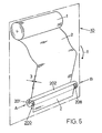
- FIG. 4 and 5 show the winding roller 100 in every detail, with the directions of consideration of Fig. 1 here correspond to the page names A and B.
- the pivot lever 102 is on its pivot point, the axis 106, has an elongated hole 105, which is a height compensation on the inserted towel allowed.
- the maximum swivel angle s of the lever 102 is over 90 ° so that the towel easily in its full width, laid over the groove 101 and through the lever 102 can be fixed in this.
- a round bar is advantageous compared to another profile bar, since it is designed in accordance with the illustration Fig. 2, engages when closing and due to the clamping effect achieved, the cloth 2 from the beginning holds securely.
- the second variant of a winding body FIGS. 6 to 13 based on the insertion of the tape material / towel 2 like a paper clip, in contrast to this it is Towel 2 in the direction of pull T, d.i. secured in the longitudinal direction, see. 6 and 10.
- Winding roller 200 represents.
- a clamping rail 202 provided which clamps the towel 2 and the in a tapered transition point 213 in one Side flange 211 is held resiliently with journal 207.
- the clamping rail 202 as well as the rest of the periphery of the Winding roller 200 is provided with friction surfaces 208; the left journal - on side A - is labeled 207 '.
- Figure 7 shows the winding roller in plan view of the clamping rail 202, while FIG. 8 shows this rotated by 90 °.
- FIG. 9 shows a base body 210 from a commercially available one Plastic, with a friction surface 208, formed from axially parallel grooves.
- This body 210 is with a provided substantially rectangular groove 201, which over the entire length of the body runs.
- Support strips 217 can be seen, which the strip material 2 in Secure connection with clamping rail 202.
- a center hole 214 is embedded.
- Figure 9 in conjunction with Figure 10 indicates the hollow box-like Structure of the base body 210.
- Rectangular recesses 216 serve to assemble (snap in) individual parts, which are preformed.
- 11 is the front end of the winding roller 200 to see, here one end of a towel 2 between the base body 210 and the clamping rail 202 clamped, is drawn.
- FIG. 12 shows the winding roller 200, in a top view from A viewed from, with towel 2 inserted, this one thrown several times, with an overall large wrap angle and also under the pressure of the clamping rail 202 in the direction of pull ⁇ T - with normal loads - immovable is captured.
- FIG. 13 shows the clamping rail 202 in its whole length in a top view - from the cloth side considered - together with their one-piece side flange 211 and the tongue formed at the opposite end 203.
- Another bearing journal 207 can be seen on the right and an inner centering pin 215 and a resilient one Transition point 213 to the spring part 206 with its one-piece bar 205.
- the clamping rail 202 is fixed in this.
- the stamp-shaped formed bar 205 is tapered at both ends designed and in their characteristic right-hand side Profile shape recorded in Figure 15; please refer Cuts A-A to D-D.
- Polycarbonate was used as the material for the clamping rail 202 and an acrylonitrile-butadiene-styrene copolymer was used for the friction surfaces 108 and 208 (ABS) selected.
- ABS acrylonitrile-butadiene-styrene copolymer
Landscapes
- Health & Medical Sciences (AREA)
- Public Health (AREA)
- Winding Of Webs (AREA)
- Treatment Of Fiber Materials (AREA)
Description
- Fig. 1
- eine typische Anordnung des Bandmaterials in einem Handtuchspender mit textilem Bandmaterial und untenliegender wickelwalze,
- Fig. 2
- die Wickelwalze Fig. 1 von links betrachtet, in vergrösserter Darstellung
- Fig. 3
- die Wickelwalze Fig. 1 von rechts betrachtet,
- Fig. 4
- die Wickelwalze mit ihrem Schwenkebel in einer vergrösserten Teil-Schnittdarstellung,
- Fig. 5
- die Wickelwalze, Fig. 4, in einer Draufsicht, mit eingelegtem Bandmaterial,
- Fig. 6
- eine analoge Anordnung zu Fig. 1, mit einer Variante einer Wickelwalze mit einer Klemmschiene,
- Fig. 7
- die Wickelwalze aus Fig. 6 in einer vergrösserter Draufsicht,
- Fig. 8
- die Wickelwalze Fig. 7 in einer um 90° gedrehten Ansicht,
- Fig. 9
- den Grundkörper der wickelwalze Fig. 7, in Draufsicht,
- Fig. 10
- die Endpartie links des Grundkörpers in einer Perspektivdarstellung,
- Fig. 11
- die Endpartie des vollständigen Wickelkörpers mit einem eingelegten Handtuch,
- Fig. 12
- eine Draufsicht von vorne auf die Wickelwalze, welche die Zick-Zack- Führung des Handtuchs aufzeigt,
- Fig. 13
- die Klemmschiene der Wickelwalze Fig. 7 und Fig. 8,
- Fig. 14
- eine Perspktivdarstellung der Unterseite der Endpartie der Klemmschiene Fig. 13 und
- Fig. 15
- charakteristische Querschnitte der Endpartie der Klemmschiene Fig. 13.
Claims (10)
- Austauschbare Wickelwalze (100) für flächiges Bandmaterial (2) in einen Handtuchspender (10), welche zumindest partiell eine an das zu wickelnden Bandmaterial (2) angepasste Reibfläche (108) aufweist und dieses endseitig kraftschlüssig auf einem Teil der Breite der Wickelwalze (100) rutschfest fixierbar ist, dadurch gekennzeichnet, dass in der Wickelwalze (100) eine achsparallele Nut (101) vorgesehen ist, in welche ein auf einer Seite der Wickelwalze (100) gelagerter Schwenkhebel (102) einlegbar ist, dass die Breite (109) der Nut (101) der Breite (110) des Schwenkhebels (102) und zusätzlich wenigstens der zweifachen Dicke (3) des Bandmaterials (2), im gepressten Zustand , entspricht.
- Austauschbare Wickelwalze (200) für flächiges Bandmaterial (2) in einen Handtuchspender (10), welche zumindest partiell eine an das zu wickelnden Bandmaterial (2) angepasste Reibfläche (108) aufweist und dieses endseitig kraftschlüssig auf einem Teil der Breite der Wickelwalze (200) rutschfest fixierbar ist, dadurch gekennzeichnet, dass in der Wickelwalze (200) eine achsparallele Nut (201) vorgesehen ist, in welche eine, auf einer Seite der Wickelwalze (200) gehaltene, federnde Klemmschiene (202) eingreift, dass die Klemmschiene (202) auf ihrer frei, über eine stirnseitige Ausnehmung der wickelwalze (200) hinausragenden Seite (A) gerundet und in eine Zunge (203) auslaufend, ausgestaltet ist.
- Wickelwalze (100;200) nach einem der Ansprüche 1 oder 2, dadurch gekennzeichnet, dass diese achsparallele Rillen (108;208) aufweist, welche in ihrem Abstand auf die Textur des Bandmaterials (2) abgestimmt sind.
- Wickelwalze (100) nach Anspruch 1 oder 3, dadurch gekennzeichnet, dass die Nut (101) im Bereich der Peripherie der Walze (100) schmaler ist als der in einem darunter liegenden Bereich mit kreisförmigen Querschnitt und dass der einlegbare Schwenkhebel (102) ebenfalls einen kreisförmigen Querschnitt aufweist, dessen Durchmesser um mehr als die zweifachen Dicke (3) des Bandmaterials (2), im gepressten Zustand, kleiner ist.
- Wickelwalze (200) nach Anspruch 2 oder 3, dadurch gekennzeichnet, dass die federnde Klemmschiene (202) einstückig mit einem seitlich an der Wickelwalze (200) angeordneten kreisförmigen Flansch (211) verbunden ist.
- Wickelwalze (200) nach Anspruch 2 oder 5, dadurch gekennzeichnet, dass die achsparallele Nut (201) mehrere zueinander parallele und orthogonal zu der Nut (201) angeordnete Stützleisten (217) aufweist, auf welche die federnde Klemmschiene (202) drückt.
- Wickelwalze (200) nach einem der Ansprüche 2, 3, 5, oder 6 dadurch gekennzeichnet, dass die Aussenseite der Klemmschiene (202) den gleichen Radius und die gleichen achsparallelen Rillen (208) aufweist wie die Wickelwalze (200).
- Wickelwalze (200) nach wenigstens einem der Ansprüche 2 oder 5 bis 7, dadurch gekennzeichnet, dass der Querschnitt (205,206) der Klemmschiene (202) annähernd eine T-form aufweist, welche gerundete Seitenflächen besitzt.
- Wickelwalze (100;200) nach Anspruch 1 oder 2, dadurch gekennzeichnet, dass diese zentrische, stirnseitig herausragende Lagerzapfen (107;207) aufweist.
- Wickelwalze (100;200) nach Anspruch 1, 2 oder 9, dadurch gekennzeichnet, dass diese im wesentlichen aus einem Thermoplast besteht.
Applications Claiming Priority (1)
| Application Number | Priority Date | Filing Date | Title |
|---|---|---|---|
| PCT/CH1999/000197 WO2000069319A1 (de) | 1999-05-12 | 1999-05-12 | Wickelwalze für einen handtuchspender |
Publications (2)
| Publication Number | Publication Date |
|---|---|
| EP1176898A1 EP1176898A1 (de) | 2002-02-06 |
| EP1176898B1 true EP1176898B1 (de) | 2004-10-13 |
Family
ID=4551676
Family Applications (1)
| Application Number | Title | Priority Date | Filing Date |
|---|---|---|---|
| EP99917730A Expired - Lifetime EP1176898B1 (de) | 1999-05-12 | 1999-05-12 | Wickelwalze für einen handtuchspender |
Country Status (4)
| Country | Link |
|---|---|
| EP (1) | EP1176898B1 (de) |
| AU (1) | AU3592899A (de) |
| DE (1) | DE59910865D1 (de) |
| WO (1) | WO2000069319A1 (de) |
Families Citing this family (1)
| Publication number | Priority date | Publication date | Assignee | Title |
|---|---|---|---|---|
| EP2196123A1 (de) | 2008-12-11 | 2010-06-16 | Rentokil Initial 1927 PLC | Handtuchrolle |
Family Cites Families (4)
| Publication number | Priority date | Publication date | Assignee | Title |
|---|---|---|---|---|
| DE3432694A1 (de) * | 1984-09-06 | 1986-03-13 | Erich Schumm Gmbh, 7157 Murrhardt | Handtuch-spender |
| FI861943A7 (fi) * | 1985-05-10 | 1986-11-11 | Nokia Limited | Handduksautomat. |
| CH689782A5 (de) | 1995-04-19 | 1999-11-15 | Cws Ag | Verfahren und Vorrichtung zum Einfaedeln und/oder Bewegen von flaechigem Bandmaterial in einem Handtuchspender. |
| EP0821562B1 (de) * | 1995-04-19 | 2000-06-28 | Cws International Ag | Ausgabe von bandmaterial zum händetrocknen |
-
1999
- 1999-05-12 AU AU35928/99A patent/AU3592899A/en not_active Abandoned
- 1999-05-12 DE DE1999510865 patent/DE59910865D1/de not_active Expired - Lifetime
- 1999-05-12 EP EP99917730A patent/EP1176898B1/de not_active Expired - Lifetime
- 1999-05-12 WO PCT/CH1999/000197 patent/WO2000069319A1/de not_active Ceased
Also Published As
| Publication number | Publication date |
|---|---|
| AU3592899A (en) | 2000-12-05 |
| WO2000069319A1 (de) | 2000-11-23 |
| EP1176898A1 (de) | 2002-02-06 |
| DE59910865D1 (de) | 2004-11-18 |
Similar Documents
| Publication | Publication Date | Title |
|---|---|---|
| AT512607B1 (de) | Spendesystem | |
| CH633491A5 (de) | Spender fuer bahnfoermiges material. | |
| EP0005555B1 (de) | Patientenliege- oder Sitzeinrichtung mit Papierspenderrolle | |
| DE1499082A1 (de) | Vorrichtung zum Abrollen von Draht | |
| EP0479001B1 (de) | Wechselkassette | |
| DE8900818U1 (de) | Vorrichtung zum Ab- und Wiederaufrollen von Bodenbelagsmaterialien | |
| DE2931053A1 (de) | Abgabevorrichtung fuer blattfoermiges, insbesondere auf einem halter aufgebrachtes material | |
| WO2000069319A1 (de) | Wickelwalze für einen handtuchspender | |
| EP0718229A1 (de) | Vorrichtung zum Ausstreifen einer laufenden Warenbahn | |
| DE2501319B2 (de) | Abrollmaschine für Stranggut | |
| WO2017165985A1 (de) | Wickeldorn sowie handtuchspender und verfahren zu seinem betrieb | |
| DE3513558A1 (de) | Klebebandabreissvorrichtung fuer klebebandrollen | |
| DE2715526C2 (de) | ||
| EP1395433B1 (de) | Antreibbare tuch-wickelrolle | |
| DE29823477U1 (de) | Vorrichtung zum abrollbaren Halten einer Papierrolle | |
| DE19607146A1 (de) | Bremsanordnung für eine in einem Gehäuse eingebaute selbstaufwickelnde Kabeltrommel | |
| EP0130473A2 (de) | Abwickelvorrichtung für Adern von Spulen in der Kabelindustrie | |
| EP0435883B1 (de) | Haspelanlage | |
| CH658681A5 (de) | Zentral schaltbare fadenbremsvorrichtung. | |
| DE3446692A1 (de) | Doppelspulvorrichtung | |
| DE638919C (de) | Haltevorrichtung fuer ueber Kopf abzuziehende lockere Fadenwickel, z. B. Kunstseidespinnkuchen | |
| DE4103110A1 (de) | Garnspulenhalter | |
| DE2555978A1 (de) | Handtuchausgeber | |
| DE69207023T2 (de) | Verfahren und Vorrichtung zum Befestigen des Fadenendes einer Spule | |
| DE3036420A1 (de) | Fadenbremse fuer textilmaschinen |
Legal Events
| Date | Code | Title | Description |
|---|---|---|---|
| PUAI | Public reference made under article 153(3) epc to a published international application that has entered the european phase |
Free format text: ORIGINAL CODE: 0009012 |
|
| 17P | Request for examination filed |
Effective date: 20011114 |
|
| AK | Designated contracting states |
Kind code of ref document: A1 Designated state(s): AT BE CH CY DE DK ES FI FR GB GR IE IT LI LU MC NL PT SE |
|
| DAX | Request for extension of the european patent (deleted) | ||
| GRAP | Despatch of communication of intention to grant a patent |
Free format text: ORIGINAL CODE: EPIDOSNIGR1 |
|
| RBV | Designated contracting states (corrected) |
Designated state(s): CH DE FR GB IT LI NL |
|
| GRAS | Grant fee paid |
Free format text: ORIGINAL CODE: EPIDOSNIGR3 |
|
| GRAA | (expected) grant |
Free format text: ORIGINAL CODE: 0009210 |
|
| AK | Designated contracting states |
Kind code of ref document: B1 Designated state(s): CH DE FR GB IT LI NL |
|
| REG | Reference to a national code |
Ref country code: GB Ref legal event code: FG4D Free format text: NOT ENGLISH |
|
| REG | Reference to a national code |
Ref country code: CH Ref legal event code: EP |
|
| RAP2 | Party data changed (patent owner data changed or rights of a patent transferred) |
Owner name: HTS INTERNATIONAL TRADING AG |
|
| REG | Reference to a national code |
Ref country code: IE Ref legal event code: FG4D Free format text: GERMAN |
|
| REF | Corresponds to: |
Ref document number: 59910865 Country of ref document: DE Date of ref document: 20041118 Kind code of ref document: P |
|
| REG | Reference to a national code |
Ref country code: CH Ref legal event code: NV Representative=s name: PPS POLYVALENT PATENT SERVICE AG |
|
| GBT | Gb: translation of ep patent filed (gb section 77(6)(a)/1977) |
Effective date: 20041115 |
|
| NLT2 | Nl: modifications (of names), taken from the european patent patent bulletin |
Owner name: HTS INTERNATIONAL TRADING AG |
|
| REG | Reference to a national code |
Ref country code: IE Ref legal event code: FD4D |
|
| PLBE | No opposition filed within time limit |
Free format text: ORIGINAL CODE: 0009261 |
|
| STAA | Information on the status of an ep patent application or granted ep patent |
Free format text: STATUS: NO OPPOSITION FILED WITHIN TIME LIMIT |
|
| ET | Fr: translation filed | ||
| 26N | No opposition filed |
Effective date: 20050714 |
|
| REG | Reference to a national code |
Ref country code: CH Ref legal event code: PFA Owner name: HTS INTERNATIONAL TRADING AG Free format text: HTS INTERNATIONAL TRADING AG#OBERNEUHOFSTRASSE 5#CH-6340 BAAR (CH) -TRANSFER TO- HTS INTERNATIONAL TRADING AG#OBERNEUHOFSTRASSE 5#CH-6340 BAAR (CH) |
|
| REG | Reference to a national code |
Ref country code: FR Ref legal event code: PLFP Year of fee payment: 18 |
|
| PGFP | Annual fee paid to national office [announced via postgrant information from national office to epo] |
Ref country code: NL Payment date: 20160509 Year of fee payment: 18 |
|
| PGFP | Annual fee paid to national office [announced via postgrant information from national office to epo] |
Ref country code: GB Payment date: 20160512 Year of fee payment: 18 Ref country code: DE Payment date: 20160531 Year of fee payment: 18 |
|
| PGFP | Annual fee paid to national office [announced via postgrant information from national office to epo] |
Ref country code: FR Payment date: 20160512 Year of fee payment: 18 Ref country code: IT Payment date: 20160531 Year of fee payment: 18 |
|
| PGFP | Annual fee paid to national office [announced via postgrant information from national office to epo] |
Ref country code: CH Payment date: 20160823 Year of fee payment: 18 |
|
| REG | Reference to a national code |
Ref country code: DE Ref legal event code: R119 Ref document number: 59910865 Country of ref document: DE |
|
| REG | Reference to a national code |
Ref country code: CH Ref legal event code: PL |
|
| REG | Reference to a national code |
Ref country code: NL Ref legal event code: MM Effective date: 20170601 |
|
| GBPC | Gb: european patent ceased through non-payment of renewal fee |
Effective date: 20170512 |
|
| PG25 | Lapsed in a contracting state [announced via postgrant information from national office to epo] |
Ref country code: CH Free format text: LAPSE BECAUSE OF NON-PAYMENT OF DUE FEES Effective date: 20170531 Ref country code: LI Free format text: LAPSE BECAUSE OF NON-PAYMENT OF DUE FEES Effective date: 20170531 |
|
| REG | Reference to a national code |
Ref country code: FR Ref legal event code: ST Effective date: 20180131 |
|
| PG25 | Lapsed in a contracting state [announced via postgrant information from national office to epo] |
Ref country code: NL Free format text: LAPSE BECAUSE OF NON-PAYMENT OF DUE FEES Effective date: 20170601 |
|
| PG25 | Lapsed in a contracting state [announced via postgrant information from national office to epo] |
Ref country code: GB Free format text: LAPSE BECAUSE OF NON-PAYMENT OF DUE FEES Effective date: 20170512 Ref country code: DE Free format text: LAPSE BECAUSE OF NON-PAYMENT OF DUE FEES Effective date: 20171201 |
|
| PG25 | Lapsed in a contracting state [announced via postgrant information from national office to epo] |
Ref country code: IT Free format text: LAPSE BECAUSE OF NON-PAYMENT OF DUE FEES Effective date: 20170512 Ref country code: FR Free format text: LAPSE BECAUSE OF NON-PAYMENT OF DUE FEES Effective date: 20170531 |