EP1176279B1 - Sectional door - Google Patents
Sectional door Download PDFInfo
- Publication number
- EP1176279B1 EP1176279B1 EP00116448.2A EP00116448A EP1176279B1 EP 1176279 B1 EP1176279 B1 EP 1176279B1 EP 00116448 A EP00116448 A EP 00116448A EP 1176279 B1 EP1176279 B1 EP 1176279B1
- Authority
- EP
- European Patent Office
- Prior art keywords
- drive motor
- rail
- runner rail
- door leaf
- door
- Prior art date
- Legal status (The legal status is an assumption and is not a legal conclusion. Google has not performed a legal analysis and makes no representation as to the accuracy of the status listed.)
- Expired - Lifetime
Links
Images


Classifications
-
- E—FIXED CONSTRUCTIONS
- E05—LOCKS; KEYS; WINDOW OR DOOR FITTINGS; SAFES
- E05D—HINGES OR SUSPENSION DEVICES FOR DOORS, WINDOWS OR WINGS
- E05D15/00—Suspension arrangements for wings
- E05D15/16—Suspension arrangements for wings for wings sliding vertically more or less in their own plane
- E05D15/24—Suspension arrangements for wings for wings sliding vertically more or less in their own plane consisting of parts connected at their edges
- E05D15/244—Upper part guiding means
- E05D15/246—Upper part guiding means with additional guide rail for producing an additional movement
-
- E—FIXED CONSTRUCTIONS
- E05—LOCKS; KEYS; WINDOW OR DOOR FITTINGS; SAFES
- E05F—DEVICES FOR MOVING WINGS INTO OPEN OR CLOSED POSITION; CHECKS FOR WINGS; WING FITTINGS NOT OTHERWISE PROVIDED FOR, CONCERNED WITH THE FUNCTIONING OF THE WING
- E05F15/00—Power-operated mechanisms for wings
- E05F15/60—Power-operated mechanisms for wings using electrical actuators
- E05F15/603—Power-operated mechanisms for wings using electrical actuators using rotary electromotors
- E05F15/665—Power-operated mechanisms for wings using electrical actuators using rotary electromotors for vertically-sliding wings
- E05F15/668—Power-operated mechanisms for wings using electrical actuators using rotary electromotors for vertically-sliding wings for overhead wings
- E05F15/67—Power-operated mechanisms for wings using electrical actuators using rotary electromotors for vertically-sliding wings for overhead wings operated by flexible or rigid rack-and-pinion arrangements
-
- E—FIXED CONSTRUCTIONS
- E05—LOCKS; KEYS; WINDOW OR DOOR FITTINGS; SAFES
- E05Y—INDEXING SCHEME RELATING TO HINGES OR OTHER SUSPENSION DEVICES FOR DOORS, WINDOWS OR WINGS AND DEVICES FOR MOVING WINGS INTO OPEN OR CLOSED POSITION, CHECKS FOR WINGS AND WING FITTINGS NOT OTHERWISE PROVIDED FOR, CONCERNED WITH THE FUNCTIONING OF THE WING
- E05Y2201/00—Constructional elements; Accessories therefore
- E05Y2201/40—Motors; Magnets; Springs; Weights; Accessories therefore
- E05Y2201/43—Motors
- E05Y2201/434—Electromotors; Details thereof
-
- E—FIXED CONSTRUCTIONS
- E05—LOCKS; KEYS; WINDOW OR DOOR FITTINGS; SAFES
- E05Y—INDEXING SCHEME RELATING TO HINGES OR OTHER SUSPENSION DEVICES FOR DOORS, WINDOWS OR WINGS AND DEVICES FOR MOVING WINGS INTO OPEN OR CLOSED POSITION, CHECKS FOR WINGS AND WING FITTINGS NOT OTHERWISE PROVIDED FOR, CONCERNED WITH THE FUNCTIONING OF THE WING
- E05Y2201/00—Constructional elements; Accessories therefore
- E05Y2201/60—Suspension or transmission members; Accessories therefore
- E05Y2201/622—Suspension or transmission members elements
- E05Y2201/686—Rods, links
-
- E—FIXED CONSTRUCTIONS
- E05—LOCKS; KEYS; WINDOW OR DOOR FITTINGS; SAFES
- E05Y—INDEXING SCHEME RELATING TO HINGES OR OTHER SUSPENSION DEVICES FOR DOORS, WINDOWS OR WINGS AND DEVICES FOR MOVING WINGS INTO OPEN OR CLOSED POSITION, CHECKS FOR WINGS AND WING FITTINGS NOT OTHERWISE PROVIDED FOR, CONCERNED WITH THE FUNCTIONING OF THE WING
- E05Y2600/00—Mounting or coupling arrangements for elements provided for in this subclass
- E05Y2600/40—Mounting location; Visibility of the elements
- E05Y2600/46—Mounting location; Visibility of the elements in or on the wing
-
- E—FIXED CONSTRUCTIONS
- E05—LOCKS; KEYS; WINDOW OR DOOR FITTINGS; SAFES
- E05Y—INDEXING SCHEME RELATING TO HINGES OR OTHER SUSPENSION DEVICES FOR DOORS, WINDOWS OR WINGS AND DEVICES FOR MOVING WINGS INTO OPEN OR CLOSED POSITION, CHECKS FOR WINGS AND WING FITTINGS NOT OTHERWISE PROVIDED FOR, CONCERNED WITH THE FUNCTIONING OF THE WING
- E05Y2900/00—Application of doors, windows, wings or fittings thereof
- E05Y2900/10—Application of doors, windows, wings or fittings thereof for buildings or parts thereof
- E05Y2900/106—Application of doors, windows, wings or fittings thereof for buildings or parts thereof for garages
Definitions
- the invention relates to a sectional door with a multi-part door panel consisting of articulated panels according to the preamble of claim 1.
- the sectional door according to the invention is in particular a garage door.
- a sectional door is known ( DE-A 198 08 696 ) in which all the panels are guided in lateral curved rails, which have a substantially vertical portion parallel to the door frame, a horizontal portion and an arc connecting the two sections.
- the electric door drive is equipped with a movable along the horizontal portion of the sheet rail drive unit which is connected by a coupling rod with the top panel of the door leaf.
- this known sectional door has the disadvantage that the door leaf on the top panel from the outside to the inside of the garage can be pressed relatively easily.
- a drive for sectional doors is known, which is suitable for a bow and in a straight direction movable sliding gates.
- a traveling drive unit is mounted on a wing of the multi-member door so that it can follow the path curvatures.
- a drive gear of the motor engages in a toothed belt, which is clamped at the ends stationary and is supported in the arc of a console.
- the drive assembly has no special measures to prevent the unauthorized pressing of the door.
- the invention the technical problem of providing a sectional door of the type mentioned above, which is optimally secured against unauthorized opening from the outside and in which nonetheless an informal and reliable opening and closing movement of the door leaf is guaranteed.
- the term drive motor means in the context of the invention, the entire drive unit with electric motor, drive wheel, any guide rollers and the like, which is movable on the upper track rail. That according to claim 1, the drive motor is substantially movable in the horizontal region of the upper track, means in particular that the drive motor is not moved in the vertical end portion of the upper track rail. It is therefore within the scope of the invention that the drive motor always performs a horizontal drive movement.
- the uppermost panel of the door leaf is guided on both sides of the door leaf in a substantially horizontal upper track, which has a front vertical end portion.
- Vertical end portion of the upper runner means according to a preferred embodiment of the invention, an exactly vertical end portion or a substantially vertically disposed end portion. According to a further embodiment of the invention, however, the term “vertical end portion” also encompasses end portions which include an angle greater than 90 ° and up to 120 ° with the horizontal portion of the upper track rail.
- the top panel is suitably performed with only one impeller in the upper rails.
- the other panels of the sectional door are guided with wheels in a lower rail, which is designed as a curved rail. It has a substantially vertical section parallel to the door frame and a substantially horizontal section directly below the upper track rail.
- the bow rail is further equipped with a bow connecting the two sections.
- a flexible strand element is provided on the upper running rail.
- the drive motor has a drive wheel, which is guided in the upper running rail and is partially looped around by the strand element.
- the strand element is designed so that the running rail facing the bottom of the strand element interacts with the surface of the drive wheel by positive engagement.
- the strand element is set under pretension.
- the strand element is a toothed belt.
- the drive wheel is designed as a pinion or gear, so that the drive motor during a rotation of the pinion through Positive connection between the pinion and the toothed belt along the track rail is movable.
- the toothing of the toothed belt is provided on the underside of the toothed belt facing the running rail.
- the drive motor has two guide rollers, which run along the top of the strand element facing away from the running rail in the process of driving the drive motor.
- the drive wheel of the drive motor is arranged in the middle between the two guide rollers.
- the drive motor furthermore has at least one guide slide element, preferably two guide slide elements, which ensure a functionally reliable sliding of the drive motor on the upper slide rail by a positive connection with the upper slide rail.
- the positive connection with the upper running rail is realized in that such a guide slide element covers or comprises a side wall of the upper running rail.
- the drive motor preferably has a self-locking gear. This ensures very effective in combination with the other features according to the invention that the door leaf of the sectional door can not be pressed from the outside.
- the connecting element between the drive motor and the door leaf expediently consists of a rigid connecting rod, which is connected via a respective articulated connection to the drive motor and preferably to the uppermost panel.
- a respective articulated connection to the drive motor and preferably to the uppermost panel.
- the invention is based on the finding that in the closed state of the door leaf pressing the door leaf from the outside to the garage interior can be effectively prevented when the teaching of the invention is realized.
- the safeguard against unauthorized pressing is realized above all by the feature, according to which in the closed position of the door leaf, the uppermost panel via a connecting element to the arranged only in the horizontal region of the track drive motor or a self-locking of the transmission of the drive motor is in combination with the other features of the invention a pressing of the door leaf on the topmost panel almost impossible.
- a linear rigid connecting element which is connected only via a hinge connection with the top panel and is connected only via a second hinge connection with the drive motor.
- the door according to the invention in particular garage door, have an emergency release in the event of a power failure.
- the emergency release can be realized, for example, via a clutch which can be actuated by a corresponding Bowden cable on the door leaf.
- the door operator is designed for use on the right and left of the gate.
- drive motors are provided on the rails on both sides of the door leaf, which are each connected via a connecting element with the door leaf and their movements are electronically synchronized.
- a trained as a sectional door garage door which has a multi-part door leaf 1, which consists of hinged panels 2, 3.
- the uppermost panel 2 of the door leaf 1 is guided on both sides of the door leaf 1 with at least one impeller 4 in a substantially horizontal upper running rail 6, which has a front vertical end portion 21.
- the vertical end portion preferably has a length of at least 5 cm.
- the remaining panels 3 are guided in a lower running rail 7, which is preferably designed and in the embodiment as a curved rail.
- the curved rail has a vertical section 9 parallel to the door frame 22, a horizontal section 10 arranged below the upper running rail 6, and a sheet 11 connecting both sections 9, 10.
- a drive motor 8 is provided, which according to the invention is movable only in the horizontal region of the upper running rail 6.
- the drive motor 8 has a drive wheel, which is designed as a pinion 14.
- the pinion 14 is guided in the upper running rail 6 and below the strand element, ie arranged below the toothed belt 13 in the exemplary embodiment.
- the drive motor 8 is moved by positive engagement of the pinion 14 with the running rail facing toothed underside of the toothed belt 13 along the upper rail 6.
- the toothed belt 13 is always lifted off the track base 12 at the location of the pinion 14 and passes over the pinion gear 14.
- the upper running rail 6 are preferably and in the embodiment also provided two running on the strand element guide rollers 15. These guide rollers 15 are arranged in the longitudinal direction of the running rail 6 on both sides of the pinion 14 and run in the embodiment on the ungeyakten back of the toothed belt 13. The guide rollers 15 contribute effectively to a secure guidance of the drive motor 8 in the upper track 6 and further support effectively the positive connection between the pinion 14 and the toothed belt 13th
- a guide sliding element 16 comprises a side wall 17 of the upper running rail 6 which originates from the runner floor 12.
- the upper running rail 6 is formed as a hollow profile which is open only on one longitudinal side. On this longitudinal side of the hollow profile, the drive wheel or pinion 14 and the guide rollers 15 engage in the upper running rail 6.
- the uppermost in the closed position panel 2 is connected via a connecting element, preferably a connecting rod 18, to the drive motor 8 ( Fig. 2 ).
- a connecting element preferably a connecting rod 18, to the drive motor 8 ( Fig. 2 ).
- the drive motor 8 In the closed position of the door leaf 1 continues to run in the upper track rail 6 impeller 4 of the top panel 2 according to the invention in the vertical end portion 21 of the upper track rail 6 a.
- the drive motor is self-locking or has a self-locking gear, a pressing of the door leaf 1 and the top panel 2 from the outside is practically impossible.
- the connecting rod 18 is connected only to the door leaf via a first articulated connection 19 and to the drive motor 8 via a second articulated connection 20, but otherwise rigidly formed.
- the angle ⁇ between the horizontal part of the upper running rail 6 and the connecting rod 18 is preferably 30 to 60 °, very preferably 35 to 55 °.
- the angle ⁇ between the uppermost panel 2 in the closed position and the connecting rod 18 is expediently 35 to 65 °, preferably 40 to 60 °.
- the above-mentioned angles have proven particularly suitable for realizing the "self-locking" according to the invention in the closed state.
- drive motors 8 are movably arranged in the previously described manner on the rails 6 on both sides of the door leaf and are connected to one of the upper panels 2, 3 by a connecting element 18 in each case.
- the driving movements of the drive motors are electronically synchronized.
Description
Die Erfindung betrifft ein Sektionaltor mit einem aus gelenkig verbundenen Paneelen bestehenden mehrteiligen Torblatt gemäß dem Oberbegriff des Anspruches 1. Bei dem erfindungsgemäßen Sektionaltor handelt es sich insbesondere um ein Garagentor.The invention relates to a sectional door with a multi-part door panel consisting of articulated panels according to the preamble of
Bei einem bekannten Sektionaltor der eingangs genannten Art (
Aus
Demgegenüber liegt der Erfindung das technische Problem zugrunde, ein Sektionaltor der eingangs genannten Art anzugeben, das gegen ein unbefugtes Öffnen von außen optimal gesichert ist und bei dem nichtsdestoweniger eine zwanglose und funktionssichere Öffnungs- und Schließbewegung des Torblattes gewährleistet ist.In contrast, the invention, the technical problem of providing a sectional door of the type mentioned above, which is optimally secured against unauthorized opening from the outside and in which nonetheless an informal and reliable opening and closing movement of the door leaf is guaranteed.
Gegenstand der Erfindung und Lösung dieser Aufgabe ist ein Sektionaltor nach Anspruch 1.The object of the invention and solution of this problem is a sectional door according to
Durch ein Verfahren des Antriebsmotors entlang der oberen Laufschiene wird die Öffnungsbewegung oder Schließbewegung des Torblattes ermöglicht. Der Begriff Antriebsmotor meint im Rahmen der Erfindung die gesamte Antriebseinheit mit Elektromotor, Antriebsrad, eventuellen Führungsrollen und dergleichen, die auf der oberen Laufschiene verfahrbar ist. Dass gemäß Patentanspruch 1 der Antriebsmotor im Wesentlichen in dem horizontalen Bereich der oberen Laufschiene verfahrbar ist, meint insbesondere, dass der Antriebsmotor nicht in dem vertikalen Endabschnitt der oberen Laufschiene verfahren wird. Es liegt somit im Rahmen der Erfindung, dass der Antriebsmotor stets eine horizontale Antriebsbewegung vollzieht.By a method of the drive motor along the upper track rail, the opening movement or closing movement of the door leaf is made possible. The term drive motor means in the context of the invention, the entire drive unit with electric motor, drive wheel, any guide rollers and the like, which is movable on the upper track rail. That according to
Das oberste Paneel des Torblatts ist an beiden Seiten des Torblattes in einer im Wesentlichen horizontalen oberen Laufschiene geführt, die einen vorderen vertikalen Endabschnitt aufweist. Vertikaler Endabschnitt der oberen Laufschiene meint nach bevorzugter Ausführungsform der Erfindung einen exakt vertikal angeordneten Endabschnitt oder einen im Wesentlichen vertikal angeordneten Endabschnitt. Nach einer weiteren Ausführungsform der Erfindung erfasst der Begriff "vertikaler Endabschnitt" jedoch auch Endabschnitte, die mit dem horizontalen Abschnitt der oberen Laufschiene einen Winkel größer als 90° und bis zu 120° einschließen.The uppermost panel of the door leaf is guided on both sides of the door leaf in a substantially horizontal upper track, which has a front vertical end portion. Vertical end portion of the upper runner means according to a preferred embodiment of the invention, an exactly vertical end portion or a substantially vertically disposed end portion. According to a further embodiment of the invention, however, the term "vertical end portion" also encompasses end portions which include an angle greater than 90 ° and up to 120 ° with the horizontal portion of the upper track rail.
Das oberste Paneel ist zweckmäßigerweise mit jeweils lediglich einem Laufrad in den oberen Laufschienen geführt. Die weiteren Paneele des Sektionaltores sind mit Laufrädern in einer unteren Laufschiene geführt, die als Bogenschiene ausgebildet ist. Sie weist einen im Wesentlichen vertikalen Abschnitt parallel zur Torzarge sowie einen im Wesentlichen horizontalen Abschnitt direkt unterhalb der oberen Laufschiene auf. Die Bogenschiene ist weiterhin mit einem die beiden genannten Abschnitte verbindenden Bogen ausgestattet.The top panel is suitably performed with only one impeller in the upper rails. The other panels of the sectional door are guided with wheels in a lower rail, which is designed as a curved rail. It has a substantially vertical section parallel to the door frame and a substantially horizontal section directly below the upper track rail. The bow rail is further equipped with a bow connecting the two sections.
Erfindungsgemäß ist an der oberen Laufschiene ein flexibles Strangelement vorgesehen. Der Antriebsmotor weist ein Antriebsrad auf, welches in der oberen Laufschiene geführt ist und vom Strangelement teilweise umschlungen ist. Bei einer Antriebsbewegung des Antriebsrades ist der Antriebsmotor durch Formschluss des Antriebsrades mit dem Strangelement längs der oberen Laufschiene verfahrbar. Das Strangelement ist so ausgebildet, dass die der Laufschiene zugewandte Unterseite des Strangelementes mit der Oberfläche des Antriebsrades durch Formschluss wechselwirkt. Zweckmäßigerweise wird das Strangelement unter Vorspannung gesetzt. Erfindungsgemäß ist das Strangelement ein Zahnriemen. Das Antriebsrad ist als Ritzel bzw. Zahnrad ausgebildet, so dass der Antriebsmotor bei einer Rotation des Ritzels durch Formschluss zwischen dem Ritzel und dem Zahnriemen längs der Laufschiene verfahrbar ist. Die Zahnung des Zahnriemens ist an der der Laufschiene zugewandten Unterseite des Zahnriemens vorgesehen.According to the invention, a flexible strand element is provided on the upper running rail. The drive motor has a drive wheel, which is guided in the upper running rail and is partially looped around by the strand element. In a drive movement of the drive wheel of the drive motor by positive engagement of the drive wheel with the strand element along the upper track rail is movable. The strand element is designed so that the running rail facing the bottom of the strand element interacts with the surface of the drive wheel by positive engagement. Conveniently, the strand element is set under pretension. According to the invention the strand element is a toothed belt. The drive wheel is designed as a pinion or gear, so that the drive motor during a rotation of the pinion through Positive connection between the pinion and the toothed belt along the track rail is movable. The toothing of the toothed belt is provided on the underside of the toothed belt facing the running rail.
Der Antriebsmotor weist zwei Führungsrollen auf, die beim Verfahren des Antriebsmotors auf der der Laufschiene abgewandten Oberseite des Strangelementes entlang laufen. Das Antriebsrad des Antriebsmotors ist in der Mitte zwischen den beiden Führungsrollen angeordnet. Vorzugsweise weist der Antriebsmotor fernerhin zumindest ein Führungsgleitelement, vorzugsweise zwei Führungsgleitelemente auf, die durch einen Formschluss mit der oberen Laufschiene ein funktionssicheres Gleiten des Antriebsmotors an der oberen Laufschiene gewährleisten. Zweckmäßigerweise wird der Formschluss mit der oberen Laufschiene dadurch verwirklicht, dass ein solches Führungsgleitelement eine Seitenwandung der oberen Laufschiene überfasst bzw. umfasst.The drive motor has two guide rollers, which run along the top of the strand element facing away from the running rail in the process of driving the drive motor. The drive wheel of the drive motor is arranged in the middle between the two guide rollers. Preferably, the drive motor furthermore has at least one guide slide element, preferably two guide slide elements, which ensure a functionally reliable sliding of the drive motor on the upper slide rail by a positive connection with the upper slide rail. Conveniently, the positive connection with the upper running rail is realized in that such a guide slide element covers or comprises a side wall of the upper running rail.
Der Antriebsmotor weist vorzugsweise ein selbsthemmendes Getriebe auf. Dadurch wird in Kombination mit den übrigen erfindungsgemäßen Merkmalen sehr wirksam sichergestellt, dass das Torblatt des Sektionaltores von außen nicht aufgedrückt werden kann.The drive motor preferably has a self-locking gear. This ensures very effective in combination with the other features according to the invention that the door leaf of the sectional door can not be pressed from the outside.
Das Verbindungselement zwischen dem Antriebsmotor und dem Torblatt besteht zweckmäßig aus einer starren Verbindungsstange, die über jeweils eine Gelenkverbindung an den Antriebsmotor und vorzugsweise an das oberste Paneel angeschlossen ist. Mit anderen Worten liegt zwischen den beiden genannten Gelenkverbindungen ein gleichsam starrer Abschnitt ohne Gelenke oder flexible Bereiche.The connecting element between the drive motor and the door leaf expediently consists of a rigid connecting rod, which is connected via a respective articulated connection to the drive motor and preferably to the uppermost panel. In other words, between the two mentioned articulated connections, there is a virtually rigid section without joints or flexible areas.
Der Erfindung liegt die Erkenntnis zugrunde, dass im geschlossenen Zustand des Torblattes ein Aufdrücken des Torblattes von außen zur Garageninnenseite hin effektiv verhindert werden kann, wenn die erfindungsgemäße Lehre verwirklicht wird. Hierzu kommt es zunächst erfindungswesentlich darauf an, dass in der Schließstellung des Torblattes das Laufrad des obersten Paneels in den vertikalen Endabschnitt der oberen Laufschiene eingreift. Zum Aufdrücken des Torblattes wäre somit zunächst eine vertikale Bewegung des genannten Laufrades erforderlich. In Kombination mit dem letztgenannten Merkmal wird die Sicherung gegen unbefugtes Aufdrücken vor allem auch durch das Merkmal realisiert, wonach in der Schließstellung des Torblattes das oberste Paneel über ein Verbindungselement an den lediglich im horizontalen Bereich der Laufschiene angeordneten Antriebsmotors bzw. einer Selbsthemmung des Getriebes des Antriebsmotors wird in Kombination mit den übrigen erfindungsgemäßen Merkmalen ein Aufdrücken des Torblattes an dem obersten Paneel nahezu unmöglich. Hierzu trägt weiterhin effektiv das Verbindungselement bei, welches das Torblatt mit dem an der oberen Laufschiene verfahrbaren Antriebsmotor verbindet. Besondere Vorteile hat in diesem Zusammenhang ein lineares starres Verbindungselement, das lediglich über eine Gelenkverbindung mit dem obersten Paneel verbunden ist und lediglich über eine zweite Gelenkverbindung mit dem Antriebsmotor verbunden ist. Im Ergebnis ist im Gegensatz zu den eingangs beschriebenen bekannten Sektionaltoren bei diesem erfindungsgemäßen Sektionaltor die Gefahr ausgeschlossen, dass das Torblatt durch Druck auf das oberste Paneel von außen aufgeschoben werden kann. Obwohl durch die erfindungsgemäße Ausgestaltung des Sektionaltores ein unbefugtes Öffnen verhindert werden kann, ist aufgrund der erfindungsgemäßen Ausbildung nichtsdestoweniger eine überraschend zwanglose und funktionssichere Öffnungsbewegung und Schließbewegung des Torblattes möglich, wenn diese von einer befugten Person mittels des elektrischen Torantriebes gewollt initiiert wird.The invention is based on the finding that in the closed state of the door leaf pressing the door leaf from the outside to the garage interior can be effectively prevented when the teaching of the invention is realized. For this purpose, it is essential to the invention that, in the closed position of the door leaf, the impeller of the uppermost panel engages in the vertical end section of the upper running rail. To press the door leaf thus initially a vertical movement of said impeller would be required. In combination with the latter feature, the safeguard against unauthorized pressing is realized above all by the feature, according to which in the closed position of the door leaf, the uppermost panel via a connecting element to the arranged only in the horizontal region of the track drive motor or a self-locking of the transmission of the drive motor is in combination with the other features of the invention a pressing of the door leaf on the topmost panel almost impossible. To this end, further effectively contributes to the connecting element which connects the door leaf with the movable drive motor on the upper running rail. Particular advantages in this context a linear rigid connecting element, which is connected only via a hinge connection with the top panel and is connected only via a second hinge connection with the drive motor. As a result, in contrast to the known sectional doors described above, in this sectional door according to the invention the risk is excluded that the door leaf can be pushed by pressure on the top panel from the outside. Although unauthorized opening can be prevented by the inventive design of the sectional door, a surprisingly casual and functionally reliable opening movement and closing movement of the door leaf is nevertheless possible due to the inventive design, if it is initiated by an authorized person by means of the electric door drive wanted.
Im Übrigen kann das erfindungsgemäße Tor, insbesondere Garagentor, eine Notentriegelung für den Fall eines Stromausfalls aufweisen. Mit Hilfe der Notentriegelung kann die Blockierung aufgehoben werden, die bei einem Stromausfall durch das selbsthemmende Getriebe des Antriebsmotors entsteht. Die Notentriegelung kann beispielsweise über eine durch entsprechenden Bowdenzug am Torblatt betätigbare Kupplung verwirklicht werden. Darüber hinaus besteht zusätzlich die Möglichkeit, durch den Lauf des Antriebes eine Zusatzverriegelung zu betätigen. Schließlich und endlich ist der Torantrieb für eine Verwendung rechts und links des Tores ausgelegt. Insbesondere bei breiten Toren sind an den Laufschienen beidseits des Torblattes Antriebsmotoren vorgesehen, die jeweils über ein Verbindungselement mit dem Torblatt verbunden sind und deren Fahrbewegungen elektronisch synchronisiert werden.Incidentally, the door according to the invention, in particular garage door, have an emergency release in the event of a power failure. With the help of the emergency release, the blockage can be canceled, which arises in the event of a power failure due to the self-locking gearbox of the drive motor. The emergency release can be realized, for example, via a clutch which can be actuated by a corresponding Bowden cable on the door leaf. In addition, there is also the option to operate by the running of the drive an additional lock. Finally, the door operator is designed for use on the right and left of the gate. In particular, with wide gates drive motors are provided on the rails on both sides of the door leaf, which are each connected via a connecting element with the door leaf and their movements are electronically synchronized.
Nachfolgend wird die Erfindung anhand einer lediglich ein Ausführungsbeispiel darstellenden Zeichnung näher erläutert. Es zeigen in schematischer Darstellung:
- Fig. 1
- einen Längsschnitt durch ein Sektionaltor mit elektrischem Torantrieb im geschlossenen Zustand,
- Fig. 2
- einen Ausschnitt aus
Fig. 1 in einer gegenüberFig. 1 vergrößerten Darstellung, teilweise aufgebrochen und - Fig. 3
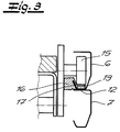
- einen Schnitt A-A durch den Gegenstand nach
Fig. 2 und - Fig. 4
- den Gegenstand nach
Fig. 1 in vollständig geöffnetem Zustand.
- Fig. 1
- a longitudinal section through a sectional door with electric door drive in the closed state,
- Fig. 2
- a section from
Fig. 1 in one oppositeFig. 1 enlarged view, partially broken and - Fig. 3
- a section AA through the object after
Fig. 2 and - Fig. 4
- the object after
Fig. 1 in fully open condition.
In den Figuren ist ein als Sektionaltor ausgebildetes Garagentor dargestellt, das ein mehrteiliges Torblatt 1 aufweist, welches aus gelenkig verbundenen Paneelen 2, 3 besteht. Das oberste Paneel 2 des Torblattes 1 ist an beiden Seiten des Torblattes 1 mit zumindest einem Laufrad 4 in einer im Wesentlich horizontalen oberen Laufschiene 6 geführt, die einen vorderen vertikalen Endabschnitt 21 aufweist. Der vertikale Endabschnitt weist vorzugsweise eine Länge von zumindest 5 cm auf. Die übrigen Paneele 3 werden in einer unteren Laufschiene 7 geführt, die vorzugsweise und im Ausführungsbeispiel als Bogenschiene ausgeführt ist. Die Bogenschiene weist einen zur Torzarge 22 parallelen vertikalen Abschnitt 9, einen unterhalb der oberen Laufschiene 6 angeordneten horizontalen Abschnitt 10 und einen beide Abschnitt 9, 10 verbindenden Bogen 11 auf.In the figures, a trained as a sectional door garage door is shown, which has a
Für eine Öffnungs- und Schließbewegung des Torblattes 1 ist ein Antriebsmotor 8 vorgesehen, der erfindungsgemäß lediglich in dem horizontalen Bereich der oberen Laufschiene 6 verfahrbar ist. Hierzu ist im Ausführungsbeispiel an der oberen Laufschiene 6 bzw. auf dem Laufschienenboden 12 der oberen Laufschiene 6 ein längs der oberen Laufschiene 6 verlaufendes flexibles und von der oberen Laufschiene 6 abhebbares Strangelement vorgesehen, das als Zahnriemen 13 ausgebildet ist. Der Antriebsmotor 8 weist ein Antriebsrad auf, das als Ritzel 14 ausgeführt ist. Das Ritzel 14 ist in der oberen Laufschiene 6 geführt und unterhalb des Strangelementes, d. h. im Ausführungsbeispiel unterhalb des Zahnriemens 13 angeordnet. Bei einer Rotation des Antriebsrades bzw. des Ritzels 14 wird der Antriebsmotor 8 durch Formschluss des Ritzels 14 mit der der Laufschiene zugewandten gezahnten Unterseite des Zahnriemens 13 längs der oberen Laufschiene 6 verfahren. Bei einer Bewegung des Antriebsmotors 8 längs dieser oberen Laufschiene 6 ist am Ort des Ritzels 14 der Zahnriemen 13 stets von dem Laufschienenboden 12 abgehoben und läuft über das Ritzel 14. Zur Führung des Antriebsmotors 8 in der oberen Laufschiene 6 sind vorzugsweise und im Ausführungsbeispiel außerdem zwei auf dem Strangelement laufende Führungsrollen 15 vorgesehen. Diese Führungsrollen 15 sind in Längsrichtung der Laufschiene 6 beidseits des Ritzels 14 angeordnet und laufen im Ausführungsbeispiel über den ungezahnten Rücken des Zahnriemens 13. Die Führungsrollen 15 tragen effektiv zu einer sicheren Führung des Antriebsmotors 8 in der oberen Laufschiene 6 bei und unterstützen fernerhin wirksam den Formschluss zwischen dem Ritzel 14 und dem Zahnriemen 13.For an opening and closing movement of the
An dem Antriebsmotor 8 sind weiterhin zwei Führungsleitelemente 16 vorgesehen. Diese Führungsgleitelemente 16 befinden sich vor den Führungsrollen 15, was in
Das in Schließstellung oberste Paneel 2 ist über ein Verbindungselement, vorzugsweise eine Verbindungsstange 18, an den Antriebsmotor 8 angeschlossen (
Die Verbindungsstange 18 ist lediglich über eine erste Gelenkverbindung 19 an das Torblatt und über eine zweite Gelenkverbindung 20 an den Antriebsmotor 8 angeschlossen, im Übrigen aber starr ausgebildet. - Der Winkel α zwischen dem horizontalen Teil der oberen Laufschiene 6 und der Verbindungsstange 18 beträgt vorzugsweise 30 bis 60°, sehr bevorzugt 35 bis 55°. Der Winkel β zwischen dem obersten Paneel 2 in Schließstellung und der Verbindungsstange 18 beträgt zweckmäßigerweise 35 bis 65°, vorzugsweise 40 bis 60°. Die vorgenannten Winkel haben sich zur Verwirklichung der erfindungsgemäßen "Selbstverriegelung" im Schließzustand besonders bewährt.The connecting
Insbesondere bei breiten Toren sind an den Laufschienen 6 beidseits des Torblattes Antriebsmotoren 8 in der zuvor beschriebenen Weise verfahrbar angeordnet und durch jeweils ein Verbindungselement 18 an eines der oberen Paneele 2, 3 angeschlossen. Die Fahrbewegungen der Antriebsmotoren sind elektronisch synchronisiert.In particular, in the case of wide gates, drive
Claims (7)
- A sectional door with a multi-part door leaf comprising panels connected in a hinged manner, wherein the uppermost panel (2) of the door leaf (1) is guided on both sides of the door leaf in an essentially horizontal upper runner rail (6), wherein further panels (3) of the door leaf (1) are guided in an arched rail which comprises an essentially vertical section (9) parallel to the door frame, an essentially horizontal section (10) directly beneath the upper runner rail (6) and an arch (11) connecting the two sections, and wherein at least one drive motor (8) is provided for the opening and closing movement of the door leaf (1), said drive motor being traversable in the horizontal region of the upper runner rail (6) and being connected by a connection element (18) to the uppermost panel (2), characterised in that
the uppermost runner rails (6) comprise a front vertical end section (21), in which a runner wheel (4) of the uppermost panel (2) guided in the upper runner rail (6) engages in the closed position of the door leaf (1),
a flexible line element which runs along the upper runner rail (6) and can be raised from the upper runner rail (6) is provided on the upper runner rail (6), said line element being constituted as a toothed belt (13),
the drive motor (8) comprises a drive wheel constituted as a sprocket (14), which is guided in the upper runner rail (6) and around which the line element is partially wound,
that the drive motor (8) comprises two guide rollers (15), which in the longitudinal direction of the runner rail (6) are disposed on both sides of the drive wheel and run over the untoothed rear of the toothed belt (13),
wherein the drive motor (8) is traversable along the upper runner rail (6) by means of the form-fit connection with the line element in the presence of a driving movement of the drive wheel. - The sectional door according to claim 1, characterised in that the toothed belt (13) lies on the runner rail base (12) of the upper runner rail (6).
- The sectional door according to claim 1 or 2, characterised in that at least one guide sliding element (16) is provided for the guidance of the drive motor (8), said guide sliding element comprising a side wall of the runner rail (6).
- The sectional door according to any one of claims 1 to 3, characterised in that two guide sliding elements (16) are provided for the guidance of the drive motor (8), said guide sliding elements being disposed one behind the other in the longitudinal direction of the runner rail (6), in each case beside a guide roll (15).
- The sectional door according to any one of claims 1 to 4, characterised in that the connection element (18) is constituted as a rigid connecting rod, which is connected in each case by a hinge connection to the drive motor (8) and the door leaf (1).
- The sectional door according to any one of claims 1 to 5, characterised in that the drive motor (8) comprises a self-locking gear unit.
- The sectional door according to any one of claims 1 to 6, characterised in that the drive motors (8) are disposed on the upper runner rail (6) on both sides of the door, which drive motors are each connected by a connection element (18) to the door leaf and the travel movements of which are synchronised electronically.
Priority Applications (4)
| Application Number | Priority Date | Filing Date | Title |
|---|---|---|---|
| PT116448T PT1176279E (en) | 2000-07-28 | 2000-07-28 | Sectional door |
| ES00116448.2T ES2449490T3 (en) | 2000-07-28 | 2000-07-28 | Sectional door |
| EP00116448.2A EP1176279B1 (en) | 2000-07-28 | 2000-07-28 | Sectional door |
| DK00116448.2T DK1176279T3 (en) | 2000-07-28 | 2000-07-28 | section Sport |
Applications Claiming Priority (1)
| Application Number | Priority Date | Filing Date | Title |
|---|---|---|---|
| EP00116448.2A EP1176279B1 (en) | 2000-07-28 | 2000-07-28 | Sectional door |
Publications (2)
| Publication Number | Publication Date |
|---|---|
| EP1176279A1 EP1176279A1 (en) | 2002-01-30 |
| EP1176279B1 true EP1176279B1 (en) | 2013-11-27 |
Family
ID=8169390
Family Applications (1)
| Application Number | Title | Priority Date | Filing Date |
|---|---|---|---|
| EP00116448.2A Expired - Lifetime EP1176279B1 (en) | 2000-07-28 | 2000-07-28 | Sectional door |
Country Status (4)
| Country | Link |
|---|---|
| EP (1) | EP1176279B1 (en) |
| DK (1) | DK1176279T3 (en) |
| ES (1) | ES2449490T3 (en) |
| PT (1) | PT1176279E (en) |
Cited By (5)
| Publication number | Priority date | Publication date | Assignee | Title |
|---|---|---|---|---|
| DE102014004428A1 (en) | 2014-03-25 | 2015-10-01 | Novoferm Tormatic Gmbh | driving device |
| DE102014004271A1 (en) | 2014-03-25 | 2015-10-01 | Novoferm Tormatic Gmbh | casing |
| DE102015008912A1 (en) | 2015-07-15 | 2017-01-19 | Novoferm Tormatic Gmbh | Portable drive unit |
| DE102015008911A1 (en) | 2015-07-15 | 2017-01-19 | Novoferm Tormatic Gmbh | Housing a portable drive device |
| DE102022120651A1 (en) | 2022-08-16 | 2024-02-22 | Hörmann KG Brockhagen | Industrial gate |
Families Citing this family (2)
| Publication number | Priority date | Publication date | Assignee | Title |
|---|---|---|---|---|
| DE10337386A1 (en) | 2002-08-13 | 2004-06-09 | Lothar Weil | guide rail for rollers of leaf of sectional door |
| EP3679214B1 (en) * | 2017-09-06 | 2023-11-22 | ASSA ABLOY Entrance Systems AB | Sectional door operator system |
Family Cites Families (5)
| Publication number | Priority date | Publication date | Assignee | Title |
|---|---|---|---|---|
| DE3538947A1 (en) * | 1985-11-02 | 1987-05-21 | Alten K | GATE, INSB. SECTIONAL GATE, FOR BUILDING OR THE LIKE. |
| DE3539657A1 (en) * | 1985-11-08 | 1987-05-21 | Alten K | SECTIONAL GATE FOR BUILDING |
| DE3602520A1 (en) * | 1986-01-28 | 1987-07-30 | Hoermann Kg | CEILING GATE AND INTERMEDIATE GUIDE FOR THE ROLLERS OF THE TOP DOOR LEAF |
| DE4123575A1 (en) | 1991-07-16 | 1993-01-21 | Kurz Rudolf Gmbh & Co | OPERATOR FOR SECTIONAL DOORS |
| DE19808696A1 (en) | 1998-02-06 | 1999-08-12 | Sommer Gmbh | Electromechanical garage door operator |
-
2000
- 2000-07-28 PT PT116448T patent/PT1176279E/en unknown
- 2000-07-28 DK DK00116448.2T patent/DK1176279T3/en active
- 2000-07-28 EP EP00116448.2A patent/EP1176279B1/en not_active Expired - Lifetime
- 2000-07-28 ES ES00116448.2T patent/ES2449490T3/en not_active Expired - Lifetime
Cited By (6)
| Publication number | Priority date | Publication date | Assignee | Title |
|---|---|---|---|---|
| DE102014004428A1 (en) | 2014-03-25 | 2015-10-01 | Novoferm Tormatic Gmbh | driving device |
| DE102014004271A1 (en) | 2014-03-25 | 2015-10-01 | Novoferm Tormatic Gmbh | casing |
| DE202014011137U1 (en) | 2014-03-25 | 2018-01-31 | Novoferm Tormatic Gmbh | casing |
| DE102015008912A1 (en) | 2015-07-15 | 2017-01-19 | Novoferm Tormatic Gmbh | Portable drive unit |
| DE102015008911A1 (en) | 2015-07-15 | 2017-01-19 | Novoferm Tormatic Gmbh | Housing a portable drive device |
| DE102022120651A1 (en) | 2022-08-16 | 2024-02-22 | Hörmann KG Brockhagen | Industrial gate |
Also Published As
| Publication number | Publication date |
|---|---|
| ES2449490T3 (en) | 2014-03-20 |
| DK1176279T3 (en) | 2014-02-03 |
| EP1176279A1 (en) | 2002-01-30 |
| PT1176279E (en) | 2014-02-27 |
Similar Documents
| Publication | Publication Date | Title |
|---|---|---|
| EP1462601B1 (en) | Sectional door | |
| DE202008018015U1 (en) | Fitting for a sliding sash | |
| EP1681420A1 (en) | Wing assembly with a sliding wing and a fixed wing | |
| EP1568563A1 (en) | Device for locking a pivotable sliding door for vehicles for passenger transport, especially vehicles for urban passenger transport | |
| DE4437250A1 (en) | Device for executing the closing and opening process of a tilt window | |
| EP1176280B1 (en) | Door, especially a garage door | |
| EP1176279B1 (en) | Sectional door | |
| EP0589180B1 (en) | Swinging and sliding door for vehicles, particularly for public transport vehicles | |
| EP1507059B1 (en) | Fitting for lifting and sliding door or window | |
| EP1312743B1 (en) | Blocking device for a liftable and sliding wing; espagnolette fitting with such a device; liftable and sliding door or window with such a device | |
| EP1366259B1 (en) | Sectional door | |
| EP1488977B1 (en) | Plugging and sliding door for a vehicle. | |
| DE3737385C2 (en) | Device for opening and closing a gate | |
| DE102006016961B4 (en) | sectional | |
| EP0731247A2 (en) | Device for securing a shutter windable about a shaft | |
| DE10003160C1 (en) | Electrically-operated door e.g. garage door, has driven running wheels displaced along horizontal guide rails received by vertical end sections of latter upon door closure | |
| EP1489250B1 (en) | Gate with holding device | |
| EP4041975A1 (en) | Opening device for a turn-tilt sash of a window or door | |
| DE10038867B4 (en) | Door system with locking device | |
| DE10257688A1 (en) | Closing device for an opening provided in a vehicle with a single slide guide rail and corresponding vehicle | |
| DE60216223T2 (en) | Motorized closing device of an opening in a vehicle and associated vehicle | |
| WO2000034609A1 (en) | Drive device for a sliding panel | |
| EP1514985A2 (en) | Locking device for vehicle doors, in particular for swinging-sliding doors of railway vehicles | |
| EP1380718B1 (en) | Device for automatically actuating a sliding door of a vehicle | |
| EP3868993B1 (en) | Sliding door, especially a cooling room sliding door |
Legal Events
| Date | Code | Title | Description |
|---|---|---|---|
| PUAI | Public reference made under article 153(3) epc to a published international application that has entered the european phase |
Free format text: ORIGINAL CODE: 0009012 |
|
| AK | Designated contracting states |
Kind code of ref document: A1 Designated state(s): AT BE CH CY DE DK ES FI FR GB GR IE IT LI LU MC NL PT SE |
|
| AX | Request for extension of the european patent |
Free format text: AL;LT;LV;MK;RO;SI |
|
| 17P | Request for examination filed |
Effective date: 20020730 |
|
| AKX | Designation fees paid |
Free format text: AT BE CH CY DE DK ES FI FR GB GR IE IT LI LU MC NL PT SE |
|
| 19A | Proceedings stayed before grant |
Effective date: 20050207 |
|
| 19F | Resumption of proceedings before grant (after stay of proceedings) |
Effective date: 20121001 |
|
| RAP1 | Party data changed (applicant data changed or rights of an application transferred) |
Owner name: NOVOFERM GMBH Owner name: HOERMANN KG BROCKHAGEN |
|
| 17Q | First examination report despatched |
Effective date: 20121011 |
|
| GRAP | Despatch of communication of intention to grant a patent |
Free format text: ORIGINAL CODE: EPIDOSNIGR1 |
|
| INTG | Intention to grant announced |
Effective date: 20130715 |
|
| GRAS | Grant fee paid |
Free format text: ORIGINAL CODE: EPIDOSNIGR3 |
|
| GRAA | (expected) grant |
Free format text: ORIGINAL CODE: 0009210 |
|
| AK | Designated contracting states |
Kind code of ref document: B1 Designated state(s): AT BE CH CY DE DK ES FI FR GB GR IE IT LI LU MC NL PT SE |
|
| REG | Reference to a national code |
Ref country code: GB Ref legal event code: FG4D Free format text: NOT ENGLISH |
|
| REG | Reference to a national code |
Ref country code: CH Ref legal event code: EP |
|
| REG | Reference to a national code |
Ref country code: AT Ref legal event code: REF Ref document number: 642813 Country of ref document: AT Kind code of ref document: T Effective date: 20131215 |
|
| REG | Reference to a national code |
Ref country code: IE Ref legal event code: FG4D Free format text: LANGUAGE OF EP DOCUMENT: GERMAN |
|
| REG | Reference to a national code |
Ref country code: DE Ref legal event code: R096 Ref document number: 50016340 Country of ref document: DE Effective date: 20140123 |
|
| REG | Reference to a national code |
Ref country code: DK Ref legal event code: T3 Effective date: 20140131 |
|
| REG | Reference to a national code |
Ref country code: SE Ref legal event code: TRGR |
|
| REG | Reference to a national code |
Ref country code: NL Ref legal event code: T3 |
|
| REG | Reference to a national code |
Ref country code: PT Ref legal event code: SC4A Free format text: AVAILABILITY OF NATIONAL TRANSLATION Effective date: 20140221 |
|
| REG | Reference to a national code |
Ref country code: ES Ref legal event code: FG2A Ref document number: 2449490 Country of ref document: ES Kind code of ref document: T3 Effective date: 20140320 |
|
| REG | Reference to a national code |
Ref country code: GR Ref legal event code: EP Ref document number: 20140400352 Country of ref document: GR Effective date: 20140317 |
|
| PG25 | Lapsed in a contracting state [announced via postgrant information from national office to epo] |
Ref country code: CY Free format text: LAPSE BECAUSE OF FAILURE TO SUBMIT A TRANSLATION OF THE DESCRIPTION OR TO PAY THE FEE WITHIN THE PRESCRIBED TIME-LIMIT Effective date: 20131127 |
|
| REG | Reference to a national code |
Ref country code: DE Ref legal event code: R097 Ref document number: 50016340 Country of ref document: DE |
|
| PLBE | No opposition filed within time limit |
Free format text: ORIGINAL CODE: 0009261 |
|
| STAA | Information on the status of an ep patent application or granted ep patent |
Free format text: STATUS: NO OPPOSITION FILED WITHIN TIME LIMIT |
|
| 26N | No opposition filed |
Effective date: 20140828 |
|
| REG | Reference to a national code |
Ref country code: DE Ref legal event code: R097 Ref document number: 50016340 Country of ref document: DE Effective date: 20140828 |
|
| PG25 | Lapsed in a contracting state [announced via postgrant information from national office to epo] |
Ref country code: LU Free format text: LAPSE BECAUSE OF FAILURE TO SUBMIT A TRANSLATION OF THE DESCRIPTION OR TO PAY THE FEE WITHIN THE PRESCRIBED TIME-LIMIT Effective date: 20140728 |
|
| REG | Reference to a national code |
Ref country code: CH Ref legal event code: PL |
|
| GBPC | Gb: european patent ceased through non-payment of renewal fee |
Effective date: 20140728 |
|
| REG | Reference to a national code |
Ref country code: IE Ref legal event code: MM4A |
|
| PG25 | Lapsed in a contracting state [announced via postgrant information from national office to epo] |
Ref country code: LI Free format text: LAPSE BECAUSE OF NON-PAYMENT OF DUE FEES Effective date: 20140731 Ref country code: CH Free format text: LAPSE BECAUSE OF NON-PAYMENT OF DUE FEES Effective date: 20140731 |
|
| PG25 | Lapsed in a contracting state [announced via postgrant information from national office to epo] |
Ref country code: GB Free format text: LAPSE BECAUSE OF NON-PAYMENT OF DUE FEES Effective date: 20140728 |
|
| PG25 | Lapsed in a contracting state [announced via postgrant information from national office to epo] |
Ref country code: IE Free format text: LAPSE BECAUSE OF NON-PAYMENT OF DUE FEES Effective date: 20140728 |
|
| PG25 | Lapsed in a contracting state [announced via postgrant information from national office to epo] |
Ref country code: MC Free format text: LAPSE BECAUSE OF FAILURE TO SUBMIT A TRANSLATION OF THE DESCRIPTION OR TO PAY THE FEE WITHIN THE PRESCRIBED TIME-LIMIT Effective date: 20131127 |
|
| REG | Reference to a national code |
Ref country code: FR Ref legal event code: PLFP Year of fee payment: 17 |
|
| REG | Reference to a national code |
Ref country code: FR Ref legal event code: PLFP Year of fee payment: 18 |
|
| REG | Reference to a national code |
Ref country code: DE Ref legal event code: R082 Ref document number: 50016340 Country of ref document: DE Representative=s name: BOEHMERT & BOEHMERT ANWALTSPARTNERSCHAFT MBB -, DE |
|
| REG | Reference to a national code |
Ref country code: FR Ref legal event code: PLFP Year of fee payment: 19 |
|
| PGFP | Annual fee paid to national office [announced via postgrant information from national office to epo] |
Ref country code: NL Payment date: 20190730 Year of fee payment: 20 |
|
| PGFP | Annual fee paid to national office [announced via postgrant information from national office to epo] |
Ref country code: DE Payment date: 20190730 Year of fee payment: 20 Ref country code: SE Payment date: 20190730 Year of fee payment: 20 Ref country code: ES Payment date: 20190822 Year of fee payment: 20 Ref country code: IT Payment date: 20190730 Year of fee payment: 20 Ref country code: PT Payment date: 20190722 Year of fee payment: 20 Ref country code: DK Payment date: 20190731 Year of fee payment: 20 Ref country code: FR Payment date: 20190730 Year of fee payment: 20 Ref country code: FI Payment date: 20190725 Year of fee payment: 20 |
|
| PGFP | Annual fee paid to national office [announced via postgrant information from national office to epo] |
Ref country code: GR Payment date: 20190725 Year of fee payment: 20 Ref country code: BE Payment date: 20190730 Year of fee payment: 20 |
|
| PGFP | Annual fee paid to national office [announced via postgrant information from national office to epo] |
Ref country code: AT Payment date: 20190731 Year of fee payment: 20 |
|
| REG | Reference to a national code |
Ref country code: DE Ref legal event code: R071 Ref document number: 50016340 Country of ref document: DE |
|
| REG | Reference to a national code |
Ref country code: NL Ref legal event code: MK Effective date: 20200727 |
|
| REG | Reference to a national code |
Ref country code: DK Ref legal event code: EUP Expiry date: 20200728 |
|
| REG | Reference to a national code |
Ref country code: FI Ref legal event code: MAE |
|
| REG | Reference to a national code |
Ref country code: BE Ref legal event code: MK Effective date: 20200728 |
|
| REG | Reference to a national code |
Ref country code: SE Ref legal event code: EUG |
|
| REG | Reference to a national code |
Ref country code: AT Ref legal event code: MK07 Ref document number: 642813 Country of ref document: AT Kind code of ref document: T Effective date: 20200728 |
|
| REG | Reference to a national code |
Ref country code: SE Ref legal event code: EUG |
|
| PG25 | Lapsed in a contracting state [announced via postgrant information from national office to epo] |
Ref country code: PT Free format text: LAPSE BECAUSE OF EXPIRATION OF PROTECTION Effective date: 20200806 |
|
| REG | Reference to a national code |
Ref country code: ES Ref legal event code: FD2A Effective date: 20201106 |
|
| PG25 | Lapsed in a contracting state [announced via postgrant information from national office to epo] |
Ref country code: ES Free format text: LAPSE BECAUSE OF EXPIRATION OF PROTECTION Effective date: 20200729 |