EP1176006A2 - Verfahren und Vorrichtung zur Herstellung eines Druckbildträgers auf vorkonfektioniertem Trägermaterial - Google Patents
Verfahren und Vorrichtung zur Herstellung eines Druckbildträgers auf vorkonfektioniertem Trägermaterial Download PDFInfo
- Publication number
- EP1176006A2 EP1176006A2 EP01113548A EP01113548A EP1176006A2 EP 1176006 A2 EP1176006 A2 EP 1176006A2 EP 01113548 A EP01113548 A EP 01113548A EP 01113548 A EP01113548 A EP 01113548A EP 1176006 A2 EP1176006 A2 EP 1176006A2
- Authority
- EP
- European Patent Office
- Prior art keywords
- carrier material
- printing
- cylinder
- polymer layer
- influenceable
- Prior art date
- Legal status (The legal status is an assumption and is not a legal conclusion. Google has not performed a legal analysis and makes no representation as to the accuracy of the status listed.)
- Withdrawn
Links
Images


Classifications
-
- B—PERFORMING OPERATIONS; TRANSPORTING
- B41—PRINTING; LINING MACHINES; TYPEWRITERS; STAMPS
- B41C—PROCESSES FOR THE MANUFACTURE OR REPRODUCTION OF PRINTING SURFACES
- B41C1/00—Forme preparation
- B41C1/10—Forme preparation for lithographic printing; Master sheets for transferring a lithographic image to the forme
- B41C1/1075—Mechanical aspects of on-press plate preparation
Definitions
- the invention relates to a method according to the preamble of claim 1 and a Device according to the preamble of claim 22.
- DE 195 36 884 C1 describes a device for wrapping a printing form cylinder with a flexible print image carrier.
- a first one Coil provided for handling a print image carrier, which on the outer surface of the printing form cylinder can be wound up, and a second winding spool for winding up of the printed image carrier mounted on the lateral surface.
- a second winding spool for winding up of the printed image carrier mounted on the lateral surface.
- the print image carrier from the first winding spool is out of this opening can be wound onto the outer surface and from the outer surface onto the second winding spool.
- the device is characterized in more detail in that a rewinding mechanism for the Storage part supporting the print image carrier from the inside of the printing form cylinder in the printing press installed condition is removably arranged.
- EP 0 770 494 A2 relates to a method for producing a printing form, which runs within a printing press.
- An image-wise exposure of one takes place Image element on a hydrophilic surface of a printing plate of an image bearing Layer.
- hydrophilic thermoplastic polymer particles in the image-bearing layer included, which are dispersed in a hydrophobic adhesive.
- EP 0 802 457 A1 describes a device for producing and imaging a Printing plate.
- a print medium is disclosed, as well as means for applying one uniform layer; they are devices for exposing the uniform layer provided in accordance with an image pattern and facilities for Develop the even layer so that an image is on the print carrier remains.
- the printed image consists of color-friendly areas on an ink-repellent one Background or repellent areas on a color-friendly background.
- the Print carrier contains a cylinder, on the peripheral surface of a plate-shaped element is attached, the surface of the plate-shaped element either color-friendly or is color-repellent.
- EP 0 802 457 A1 also describes a method for Manufacture of a printing medium disclosed, the device described above is used as well as a coating fluid to be used in this device.
- the polymer layer that can be influenced must be after printing the order from the surface of the print carrier at least largely removed before a new neutral layer, i.e. not yet from a layer irradiated with a laser light as a prerequisite for a new one to be generated Print image by imaging the printing form in the printing press for the next one Print job is applied. Even if the is not completely removed Polymer layer from the surface of the printing form cylinder after completion of the previous print job must re-liability of the next print job polymer to be applied so well that the polymer layer for the subsequent order have the same long service life on the printing form with multiple repeatability got to.
- this task is performed by a printing press with the Features solved according to claim 22.
- the carrier material is pre-assembled in roll form on winding spools.
- This offers the advantage that the polymer coming into contact with the influenceable polymer Surface neither with light nor with oxygen in for a longer period of time Comes into contact and is therefore well protected from oxidation and light.
- the surface of the carrier material in one outside of the machine Prepare clean room or vacuum environment inexpensively.
- the carrier material can be exchanged as a quickly replaceable sleeve with an influenceable one Prefabricate the polymer-absorbing outer surface.
- the quickly replaceable Sleeve could be recycled offline or, if reasonably priced, after be discarded immediately after finishing the print job.
- the sleeve-shaped Base material components can be made of steel, aluminum, GRP or suitable Polyester, for example.
- the process is the pre-assembly of the carrier material as a pre-cut plate-shaped carrier material possible. Even with such a made-up
- the carrier material is a surface for the adhesion of the polymer layer that can be influenced provided, one for applying such flat printing plate-like Carrier sections of semi-automatic or fully automatic plate feed systems can operate in a known design.
- the application of the influenceable polymer layer on the top of the for the adhesion of the Polymer layer prepared substrate can be sprayed over a Spray device or by material transfer from another medium.
- a Spray device or by material transfer from another medium.
- a moving surface could, for example, be the lateral surface of a Applicator roller or the top of a ribbon-shaped, the polymer material applying externally driven or powered by the printing press itself Represent element.
- Fixing the polymer layer on the top of the carrier material to the cylinder for example the printing form cylinder of a rotary printing press. Fixing the polymer layer on the carrier material which can be influenced can be irradiated on the one hand the applied, influenceable polymer layer on the cylinder.
- This can a radiation source can be provided, each over the width of the carrier material receiving cylinder can be operated with different intensities, what also in an analogous manner for the intensity control of the radiation source in The circumferential direction of the substrate material surface to be irradiated applies.
- the lateral surface of a printing form cylinder is also a fixation of those that can be influenced Polymer layer possible by preheating the carrier material.
- preheating of the carrier material can, for example, in the cavity of the on winding spools the winding material provided there the cylinder receiving the carrier material be flowed through with a heating medium, for example tempered water, and a Preheat the wound up stock of carrier material.
- the carrier material can on the winding spools, which in the cavity of a Printing form cylinders of a rotary printing press can be installed interchangeably, in Present film form and contain dimensionally stable polyester material.
- the slipping with a influenceable polymer layer provided carrier material can be prevented.
- the carrier material which is preferably in coil form inside the Printing form cylinder is stored, are further wound on the cylinder surface, wherein the used section of the carrier material with it received Polymer layer unwound from the outer surface and one with a new polymer layer Part of the carrier material to be provided within the printing machine the peripheral surface of the printing form cylinder can be applied.
- the carrier material is a polyester material which for the application of the polymer layer and its fixation on the surface of the Carrier material is chemically and physically prepared.
- the influenceable Polymer layer in all printing units of a multiple printing units Printing machine applied simultaneously and on the respective lateral surfaces of the Printing form cylinders are fixed. If the supply winding spool is exhausted, i. H. the the used section of the carrier material receiving winding spool with the used Filler stock filled, can be outside the rotary press Reprocessing of the used carrier material and conditioning of it Surface take place so that the inexpensive carrier material can be used several times can.
- the winding spools 5 and 6 can include.
- the winding coils 5 and 6 one of which is a supply of one Carrier material 3 takes up while the other for receiving the from the outer surface 9 unwound, that is to say use the carrier material section, the carrier material 3 depending on the print job again transported to the lateral surface 9 of the printing form cylinder 1.
- the carrier material can be influenced by a polymer layer 16, as still further will be set out to be coated.
- a supply can be provided on the winding spools 5 and 6, respectively of a carrier material 3 can be provided in a wound form, which as Plate material in roll form for the printing form cylinder 1 is used.
- a carrier material 3 can be provided in a wound form, which as Plate material in roll form for the printing form cylinder 1 is used.
- Tensioning devices wind the stock of carrier material after the print job has ended so far that a new unexposed section of the substrate 3 Encloses surface of the printing form cylinder 1 and for the next print job can be exposed.
- the material stored in roll form no longer the externally pre-coated printing plate, but rather a suitable one for the application of an influenceable polymer ready-made and prepared polyester material.
- FIGS. 1a and 1b show the condition serving as the carrier material Foil material out closer.
- Fig. 1a is the carrier material 3, which is polyester or a as already described above similar related material can be shown in a material thickness 15.
- the Material thickness 15 is preferably only a few tenths of a millimeter, so that Carrier material 3 can be referred to as a carrier film.
- the carrier film contains one Top 13 and a bottom 14 and is in the roll-shaped state in Direction of the double arrow during the spray movement in the circumferential direction on the Surface 9 or 24 of the printing form cylinder 1 is movable.
- Polyester is preferred as material for the carrier layer 3, since it remains dimensionally stable and has a long service life for has medium and higher print runs.
- the dimensional stability of a thin Polyester material 16 can u. a.
- reference numeral 19 is an application device in a schematic embodiment reproduced, at the order opening 20, a polymer spray which emerges precipitates on the surface 13 of the carrier material 3 and in the application direction A seen, an influenceable polymer layer 16 on the top 13 of the carrier material 3 builds. In the area of the adhesion area 17 are the ones that can be applied and in another area Process step of influenceable polymer layer 16 to be fixed and the upper side 13 of the carrier material 3 connected together.
- the influenceable polymer 16 can also be equipped by means of material transfer realize from a different medium to the carrier material 3.
- a contact order of the influenceable polymer 16 on the upper side 13 of the carrier material 3 for example bringing a roller body guiding the polymer layer 16 into contact or an externally driven band-shaped element, a material transfer can occur the surface 13 of the carrier material 3 can be effected.
- the carrier material 3 shown in Figures 1a, 1b and Fig. 1 can in addition to a Packing in roll form also as finite, pre-cut plate-shaped Backing material 3 are available.
- the respective on the outer surface 9 or 24 of the printing form cylinder 1 to be applied partial area of the carrier material 3 in the form a curved to the curvature of the lateral surface 9 or 24 of the printing form cylinder 1 customized printing plate.
- This can be done using known ones manual semi automatic or automatic plate changing devices from the lateral surface 9 or 24 of the printing form cylinder 1 after the end of Take off the print job and by means of these feed devices also on the latter Apply the outer surface 9 or 24.
- the carrier material 3 can also in the form of quickly replaceable sleeves, so-called sleeves, which are outside the Printing machine can be reprocessed, ready-made immediately after End of the print job can be disposed of or reprocessed.
- quickly exchangeable sleeves can be manufactured as thin polyester tubes, which at the corresponding number of pieces even after the end of a respective print job can be removed.
- the pre-assembly of the carrier material 3 as a roll material, which to the Winding spools 5 and 6 are stored in the cavity 22 of the printing form cylinder 1 can offers the advantage that the surface 13 of this carrier material 3 through the Recording in the cavity 22 of the printing form cylinder 1 on the contact surface 13, which is prepared to receive the influenceable polymer 16 over a longer period Period of time cannot come into contact with light or oxygen.
- This surface 13 of the carrier material 3 can now also be outside the machine in a clean room or a vacuum environment is extremely cost-effective getting produced.
- the carrier material 3 can, if necessary, also outside the printing press be reprocessed.
- the carrier material 3 used can be cleaned and the Surface 13 is newly prepared for the adhesion of an influenceable polymer 16, so that information can follow. This allows the consumption of Reduce carrier material 3 by using it several times.
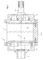
- From the representation acc. 2 is a schematic view of a printing form cylinder 1 in the interior, not shown here, below the lateral surface 9 Winding spools 5 and 6 are embedded on the side. Regardless of whether the Drive of the winding coils 5, 6 accommodated inside a printing form cylinder 1 which spool a supply of substrate material over the lateral surface 9 of the printing form cylinder 1, are driven from the outside or from the inside is this version of the
- the method proposed according to the invention has the advantage that the Carrier material before premature oxidation by the surrounding Oxygen atmosphere and protected from aging by excessive light becomes.
- the printing form cylinder 1 shown in a schematic embodiment in FIG. 2 comprises two pins 11 and 25, respectively.
- the printing form cylinder 1 is stored in the side walls of a printing unit of a rotary printing press. While its rotation around its axis of rotation can be on one of the end faces of the Printing form cylinder 1 provided gears via a locking drive or via a Gearing corresponding to the rotation of the printing form cylinder 1 about its axis Cause feed of the spoolable carrier material 3 on the lateral surface 9.
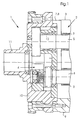
- a printing form cylinder 1 of a rotary printing press is shown, inside which there are winding coils 5 and 6 as shown in FIG. 1 have it rotatable.
- the printing form cylinder 1 has two bearing journals 11 and 25 analogous to Representation of the printing form cylinder acc. Fig. 2, with which the printing form cylinder can be rotatably accommodated in the side walls of a rotary printing press.
- the Printing form cylinder rotates about its axis of rotation 23 and includes one with an opening 2 provided lateral surface 9 or 24, on the surface of which the underside 14 of the in Fig. 1a or 1b shown carrier material 3 is present.
- the printing form cylinder acc. Fig. 3 comprises two end faces 10 and 27, in which the Ends of the winding coils 5 and 6 (see Fig. 1) can be inserted.
- bearing bushes 12 and 26 are embedded, whereas in the front side 27 of the printing form cylinder 1 pin openings 21 are formed, in which the Face 10 of the printing form cylinder 1 opposite ends of each can be stored winding coils 5 and 6. That to the Circumferential surfaces of the winding coils 5 and 6, the carrier material 3 is in the Cavity 22 of the printing form cylinder 1 added, as far as possible by this enclosed and leaves it or disappears into it through the opening 2, the one Interruption of the lateral surface 9 or 24 of the printing form cylinder 1 represents.
- Both on the lateral surfaces 9 and 24 of the printing form cylinder 1 acc. Fig. 3 as well the lateral surface 9 of the printing form cylinder acc. Fig. 2 can be next to roll-shaped assembled carrier materials 3 also pre-cut plate-shaped Fasten the carrier material sections. These can be, for example, via Clamping devices that those for the clamping of printing plates on the circumference of the Printing form cylinder 1 are similar, can be clamped in the circumferential direction. Through a Tensioning the carrier material 3 can prevent it from slipping, so that if necessary supported by magnetic adhesion or suction systems on Printing form cylinder 1, the carrier material 3 held in a reproducible position can be.
- the polymer 16 applied in this way is fixed.
- the fixation the polymer layer 16 on the contact surface 13 of the carrier material 3 can by Irradiating the polymer that can be influenced with a radiation source, for example one Infrared emitter, a UV emitter or a laser or alternatively Embodiment by preheating the carrier material 3 itself for example the winding coils 5 or 6, on the circumference of which the carrier material 3 can be taken up, so that the on the peripheral surfaces of the Winding spools 5 and 6 acc.
- Fig. 1 recorded stock of carrier material 3 in this Packaging form can already be prepared. It is also conceivable by Heating the printing form cylinder to initiate the fixation of the polymer that can be influenced.
- the polymer layer 16 After application of the polymer layer 16 to the surface 13 of the carrier material 3 and by forming an adhesive bond between the influenceable Polymer layer 16 and the carrier material 3 within the adhesion zone 17, can The polymer layer is exposed and then the printing job is pressed on.
- the carrier material is 3 during the imaging and subsequent printing process possibly supported by suction or by magnetic adhesion, dimensionally stable and non-slip on the lateral surface 9 or 24 of the printing form cylinder 1.
- After completion of the print job is in roll form when pre-assembling the carrier material 3 this only rewound by driving the winding coils 5 and 6, whereby the used Section of the carrier material with which printing has just been carried out in the cavity 22 of the Printing form cylinder 1 on the circumference of the take-up reel disappears.
- the carrier material 3 can also be used as a so-called sleeve, in Sleeve shape or in the form of finite flat plate-shaped assemblies printing plate-like sections should be filled.
- the further winding device for the carrier material 3 consists of a dispensing head 31 and a consumption head 30 which receives the used material
- the winding bobbin 3 received within the feed unit 31 is by means of a take-off roller separated from a coating, so that on a first deflecting roller only the carrier material 3 accumulates.
- a pre-assembled material 3 promoted.
- the required need for carrier material 3 it is assembled accordingly via the lateral surface 9 of the printing form cylinder 1 driven, applied to this and from the feed unit 31, i.e. from that Carrier material 3 receiving winding spools 5 and 6 separately.
- the peripheral surface 9 and 37 of the printing form cylinder 1 is thus from outside the Printing form cylinder 1 of the carrier material supply 3 arranged on the rotary printing press assign the according to the proposed method according to the invention Apply to the surface 9 or 37 of the printing form cylinder 1 to harden on this is to prevent and ensure premature wear of the carrier material 3, that after applying a layer of influenceable polymers 16 to the top of the carrier material 3, the coloring by the only schematically shown here Applicator rollers 33 takes place.
- the surface 37 and 9 of the printing form cylinder 1 are also assigned an imaging unit 34 and a Cleaning device 35.
- FIG. 5 shows a section profile perpendicular to the axis of rotation the printing form cylinder 1 in more detail.
- the printing form cylinder 1 resulting from the already described FIGS. 1 and 3 is on its outer surface 9 is provided with a pit 2 through which access to the interior 22 of the printing form cylinder 1 is guaranteed.
- Inside the printing form cylinder is one first mirror coil 5 removably mounted, which from the lateral surface 9 of the Printing form cylinder 1 to remove carrier material coating and a further winding coil 6 is provided, which a stock of carrier material 3 in Roll assembly contains, which after unrolling the used material layer 3 together with this applied polymer layer from the lateral surface 9 of the Printing form cylinder 1 is removed so that the new in the direction of arrow from the winding spool 6 Carrier material layer 3 to be developed in turn as an unused carrier material supply reaches the outer surface 9 of the printing form cylinder 1.
- this is on its lateral surface with an opening 2 through which the accessibility to Cavity 22 of the printing form cylinder 1 is guaranteed.
Landscapes
- Engineering & Computer Science (AREA)
- Mechanical Engineering (AREA)
- Manufacturing & Machinery (AREA)
- Printing Plates And Materials Therefor (AREA)
- Manufacture Or Reproduction Of Printing Formes (AREA)
- Supply, Installation And Extraction Of Printed Sheets Or Plates (AREA)
Abstract
Description
- Fig. 1
- einen teilweisen Schnitt durch einen Formzylinder mit stirnseitig gelagerten Trägermaterialspulen,
- Fig. 1a, 1b
- die Beschaffenheit des Trägermaterials mit und ohne Polymerschicht und
- Fig. 2
- einen Druckformzylinder mit außerhalb der Maschine demontierbaren Zylinderstirnseiten,
- Fig. 3
- einen Querschnitt durch einen Druckformzylinder, in dessen Hohlraum Wickelspulen zur Aufnahme eines rollenförmigen Trägermateriales auswechselbar eingelassen sind und
- Fig. 4
- eine Anordnungsmöglichkeit einer Transportvorrichtung für das aufzubringende Trägermaterial, welche außerhalb der Rotationsdruckmaschine vorgesehen ist.
- Fig. 5
- einen Schnitt durch Druckformzylinder, Übertragungszylinder sowie Gegendruckzylinder und
- 1
- Druckformzylinder
- 2
- Umfangsöffnung
- 3
- Trägermaterial
- 4
- Spulantrieb
- 5
- Wickelspule
- 6
- Wickelspule
- 7
- Rundung
- 8
- Rundung
- 9
- Mantelfläche
- 10
- Stirnseite
- 11
- Zylinderzapfen
- 12
- Spulenlager
- 13
- Kontaktseite Trägermaterial
- 14
- Unterseite Trägermaterial
- 15
- Materialstärke
- 16
- Polymerschicht
- 17
- Adhäsionsbereich
- 18
- Vorschub
- 19
- Auftragsvorrichtung
- 20
- Auftragsöffnung/Auftragsfläche
- 21
- Wickelspindellagerung
- 22
- Hohlraum
- 23
- Rotationsachse
- 24
- Mantelfläche
- 25
- Zapfen
- 26
- Wickelspulenöffnung
- 27
- Stirnseite
- 28
- Drehsinn
- 29
- Druckspalt
- 30
- Entfernungseinheit
- 31
- Zuführeinheit
- 32
- Abzugswalze
- 33
- Auftragswalze
- 34
- Bebilderungseinheit
- 35
- Reinigungsvorrichtung
- 36
- Auftragswalze
- 37
- Zylindermantelfläche
- 38
- Gegendruckzylinder
- 39
- Übertragungszylinder
- A
- Auftragsrichtung
Claims (23)
- Verfahren zur Herstellung eines Druckträgers innerhalb einer Druckmaschine
dadurch gekennzeichnet, dass ein vorkonfektioniertes Trägermaterial (3) an einem Zylinder (1) der Druckmaschine vorgesehen wird, wobei das Trägermaterial eine Kontaktfläche (13) aufweist und innerhalb der Druckmaschine eine beeinflussbares Polymer (16) auf die Kontaktfläche (13) des vorkonfektionierten Trägermaterials (3) aufgetragen wird. - Verfahren gemäß Anspruch 1,
dadurch gekennzeichnet, dass das Trägermaterial (3) rollenförmig auf Wickelspulen (5, 6) vorkonfektioniert ist. - Verfahren gemäß Anspruch 1,
dadurch gekennzeichnet, dass das Trägermaterial (3) als wechselbare Hülse mit die beeinflußbare Polymerschicht (16) aufnehmende Mantelfläche (13) vorkonfektioniert ist. - Verfahren gemäß Anspruch 1,
dadurch gekennzeichnet, dass das vorkonfektionierte Trägermaterial (3) ein vorgeschnittenes, plattenförmiges Trägermaterial (3) ist, dessen Oberfläche (13) zur Adhäsion der beeinflußbaren Polymerschicht (16) vorbereitet ist. - Verfahren gemäß Anspruch 4,
dadurch gekennzeichnet, dass das vorgeschnittene, plattenförmig konfigurierte Trägermaterial (3) über ein automatisches Wechselsystem von der Mantelfläche (9, 24) des Zylinders (1) entnommen bzw. aufgebracht wird. - Verfahren gemäß Anspruch 1,
dadurch gekennzeichnet, dass die Haftung des beeinflußbaren Polymeres (16) auf dem vorbereiteten Trägermaterial (3) durch Aufsprühen über eine Auftragseinrichtung (19) oder durch Materialübertrag von einem anderen Medium erfolgt. - Verfahren gemäß Anspruch 1,
dadurch gekennzeichnet, dass der Auftrag des beeinflußbaren Polymeres (16) durch Kontaktauftrag mit einer mitbewegten Oberfläche eines Rotationskörpers oder eines bandförmigen Elementes erfolgt. - Verfahren gemäß Anspruch 1,
dadurch gekennzeichnet, dass das Fixieren der beeinflußbaren Polymerschicht (16) auf dem Trägermaterial (3) durch Bestrahlen der aufgetragenen, beeinflußbaren Polymerschicht (16) auf dem Zylinder (1) erfolgt. - Verfahren gemäß Anspruch 1,
dadurch gekennzeichnet, dass das Fixieren der beeinflußbaren Polymerschicht (16) durch Vorwärmen des Trägermateriales (3) erfolgt. - Verfahren gemäß Anspruch 1,
dadurch gekennzeichnet, dass das Trägermaterial (3) in Folienform vorliegt und formstabiles Polyester enthält. - Verfahren gemäß Anspruch 1,
dadurch gekennzeichnet, dass das Trägermaterial (3) in Spulrichtung gerundet im Hohlraum (22) des Druckformzylinders (1) aufgenommen ist. - Verfahren gemäß Anspruch 1,
dadurch gekennzeichnet, dass das Trägermaterial (3) während des Bebilderungs- und Druckvorganges durch Ansaugen und/oder magnetischer Haftung mit der Mantelfläche (9, 24) des Druckformzylinders (1) verbunden ist. - Verfahren gemäß Anspruch 2,
dadurch gekennzeichnet, dass nach Beendigung eines Druckauftrages das Trägermaterial (3) an der Zylindermantelfläche (9, 24) weitergespult wird, der benutzte Teilabschnitt des Trägermateriales (3) von der Mantelfläche (9, 24) abgespult und ein mit einer neuen Polymerschicht (16) zu versehender Teilabschnitt des Trägermateriales (3) auf diese aufgespult wird. - Verfahren gemäß Anspruch 1,
dadurch gekennzeichnet, dass das Trägermaterial (3) ein Polyestermaterial ist, welches für den Auftrag der Polymerschicht (16) und der Fixierung an der Oberfläche (13) des Trägermateriales (3) chemisch und physikalisch vorbereitet ist. - Verfahren gemäß Anspruch 1,
dadurch gekennzeichnet, dass die beeinflußbaren Polymere (16) in sämtlichen Druckwerken einer Druckmaschine simultan aufgetragen und fixiert werden. - Verfahren gemäß Anspruch 1,
dadurch gekennzeichnet, dass der benutzte Vorrat an Trägermaterial (3) außerhalb der Druckmaschine wieder aufbereitet wird. - Verfahren gemäß Anspruch 1,
dadurch gekennzeichnet, dass der zusätzliche Verfahrensschritt des Fixierens der auf das vorbereitete Trägermaterial (3) aufgebrachten beeinflußbaren Polymerschicht (16) erfolgt. - Verfahren gemäß Anspruch 1,
dadurch gekennzeichnet, dass das vorkonfektionierte Trägermaterial ein Wickel ist, der außerhalb (30, 31) des Druckformzylinders (1) aufgebracht ist und von dem die erforderliche Länge an Trägermaterial (3) automatisch abgeschnitten und auf die Mantelfläche (9) des Druckformzylinders (1) befestigt wird. - Verfahren gemäß einem oder mehrere der vorhergehenden Ansprüche,
dadurch gekennzeichnet, dass zwischen der Mantelfläche (9) und der Unterseite des zu applizierenden Trägermateriales (3) eine, eine reibschlüssige Verbindung erzeugende Rauhigkeit vorliegt. - Verfahren gemäß Anspruch 1,
dadurch gekennzeichnet, dass die Mantelfläche (9, 37) des das Trägermaterial (3) aufnehmende Druckformzylinder (1) porös ist. - Verfahren nach einem der Ansprüche 1 bis 20,
dadurch gekennzeichnet, dass nach dem Ende des Druckauftrages das die beeinflussbare Polymerschicht (16) aufnehmbare Trägermaterial (3) weitergespult und/oder entnommen wird. - Druckmaschine mit einem Druckzylinder,
dadurch gekennzeichnet, dass eine Einrichtung zum Aufbringen eines vorkonfektionierten Trägermaterials (3) auf die Oberfläche des Druckzylinders sowie eine Einrichtung zum Auftragen eines beeinflussbaren Polymers (16) auf eine Kontaktfläche (13) des vorkonfektionierten Trägermaterials (3) vorgesehen ist. - Druckmaschine nach Anspruch 22,
dadurch gekennzeichnet, dass die Vorrichtung zum Aufbringen des vorkonfektionierten Trägermaterials (3) Wickelspulen (5, 6) aufweist.
Applications Claiming Priority (2)
| Application Number | Priority Date | Filing Date | Title |
|---|---|---|---|
| DE10037273 | 2000-07-28 | ||
| DE10037273 | 2000-07-28 |
Publications (2)
| Publication Number | Publication Date |
|---|---|
| EP1176006A2 true EP1176006A2 (de) | 2002-01-30 |
| EP1176006A3 EP1176006A3 (de) | 2003-10-15 |
Family
ID=7650840
Family Applications (1)
| Application Number | Title | Priority Date | Filing Date |
|---|---|---|---|
| EP01113548A Withdrawn EP1176006A3 (de) | 2000-07-28 | 2001-06-13 | Verfahren und Vorrichtung zur Herstellung eines Druckbildträgers auf vorkonfektioniertem Trägermaterial |
Country Status (8)
| Country | Link |
|---|---|
| US (1) | US6715419B2 (de) |
| EP (1) | EP1176006A3 (de) |
| JP (1) | JP2002103558A (de) |
| CN (1) | CN1336282A (de) |
| CA (1) | CA2350250A1 (de) |
| DE (1) | DE10128706A1 (de) |
| HK (1) | HK1043564A1 (de) |
| IL (1) | IL144538A0 (de) |
Families Citing this family (2)
| Publication number | Priority date | Publication date | Assignee | Title |
|---|---|---|---|---|
| JP2004122790A (ja) * | 2002-10-02 | 2004-04-22 | Heidelberger Druckmas Ag | 印刷フィルムを版胴に巻き付けるための方法 |
| CN119911004A (zh) * | 2025-04-03 | 2025-05-02 | 烟台吉佰士工业技术有限公司 | 一种印刷机辊 |
Family Cites Families (10)
| Publication number | Priority date | Publication date | Assignee | Title |
|---|---|---|---|---|
| US5129321A (en) | 1991-07-08 | 1992-07-14 | Rockwell International Corporation | Direct-to-press imaging system for use in lithographic printing |
| DE4303872C2 (de) * | 1992-04-24 | 1995-08-10 | Roland Man Druckmasch | Druckmaschine mit einem Formzylinder und Verfahren zur Druckvorbereitung des Formzylinders |
| US5355795A (en) * | 1993-08-26 | 1994-10-18 | Presstek, Inc. | Automatic plate-loading cylinder for use with plate-imaging systems |
| DE19602289A1 (de) | 1996-01-23 | 1997-07-24 | Roland Man Druckmasch | Druckvorrichtung |
| EP0802457A1 (de) * | 1996-04-16 | 1997-10-22 | Agfa-Gevaert N.V. | Herstellungs- und Bildaufzeichnungsverfahren für Flachdruckplatten |
| EP0847853B1 (de) | 1996-11-14 | 2001-01-24 | Kodak Polychrome Graphics LLC | Entwicklungsfreie Flachdruckplatte |
| AU5780698A (en) * | 1997-02-06 | 1998-08-26 | Star Micronics Co., Ltd. | Image formation apparatus, image formation method and plate making method |
| US5870955A (en) * | 1997-03-05 | 1999-02-16 | Presstek, Inc. | Lithographic printing system with reusable support surfaces and lithographic constructions for use therewith |
| DE19753744A1 (de) * | 1997-12-04 | 1999-06-10 | Polywest Kunststofftechnik | Walze für das rotative Bedrucken, Beschichten oder Prägen u.gl., insbesondere Druckwalze für den Flexo- oder Tiefdruck |
| JP3739962B2 (ja) * | 1998-05-18 | 2006-01-25 | 富士写真フイルム株式会社 | 平版印刷版用原版、これを用いた平版印刷版の製版方法および平版印刷版用原版の製造方法 |
-
2001
- 2001-06-11 CA CA002350250A patent/CA2350250A1/en not_active Abandoned
- 2001-06-13 DE DE10128706A patent/DE10128706A1/de not_active Ceased
- 2001-06-13 EP EP01113548A patent/EP1176006A3/de not_active Withdrawn
- 2001-07-24 IL IL14453801A patent/IL144538A0/xx unknown
- 2001-07-27 CN CN01123608A patent/CN1336282A/zh active Pending
- 2001-07-30 US US09/918,146 patent/US6715419B2/en not_active Expired - Fee Related
- 2001-07-30 JP JP2001230071A patent/JP2002103558A/ja active Pending
-
2002
- 2002-07-16 HK HK02105241.4A patent/HK1043564A1/zh unknown
Also Published As
| Publication number | Publication date |
|---|---|
| EP1176006A3 (de) | 2003-10-15 |
| HK1043564A1 (zh) | 2002-09-20 |
| US20020033107A1 (en) | 2002-03-21 |
| DE10128706A1 (de) | 2002-02-07 |
| IL144538A0 (en) | 2002-05-23 |
| JP2002103558A (ja) | 2002-04-09 |
| US6715419B2 (en) | 2004-04-06 |
| CA2350250A1 (en) | 2002-01-28 |
| CN1336282A (zh) | 2002-02-20 |
Similar Documents
| Publication | Publication Date | Title |
|---|---|---|
| EP0225509B2 (de) | Vorrichtung zum Bedrucken einer Bahn | |
| DE4303872C2 (de) | Druckmaschine mit einem Formzylinder und Verfahren zur Druckvorbereitung des Formzylinders | |
| EP0963839B1 (de) | Druckmaschine und Druckverfahren | |
| DE69402638T2 (de) | Druckplattenzylinder mit einer Einrichtung zum automatischen Zuführen von Druckplattenmaterial zur Verwendung in einem System zur Herstellung von Druckplatten | |
| DE19612927B4 (de) | Druckmaschine und Bilderzeugungsverfahren für eine Druckmaschine | |
| EP0788880B1 (de) | Druckmaschine mit mindestens einem auswechselbaren Formzylinder | |
| EP3169521B1 (de) | Vorrichtung zum bedrucken von hohlkörpern | |
| EP0906825A2 (de) | Verfahren zum Betrieb einer Rotationsdruckmaschine und Vorrichtung zur Durchführung des verfahrens | |
| EP1170122B1 (de) | Einrichtung in Druckmaschinen zum Bebildern von Oberflächen | |
| DE102008054516A1 (de) | Modulare Folieneinheit | |
| DE4224332A1 (de) | Plattenzylinder für Rotationsdruckmaschinen | |
| DE69422421T2 (de) | Farbwerk für Druckmaschinen | |
| DE10129752A1 (de) | Mehrfarben-Druckmaschine mit einem gemeinsamen Gummituchzylinder | |
| DE60030405T2 (de) | Doppel-plattenaufwicklungsvorrichtung mit spannungeinstellung | |
| DE69711331T2 (de) | Verfahren zum Betrieb eines Thermodruckers | |
| EP1112860B1 (de) | Verfahren zur fortlaufenden Herstellung von hülsenförmigen, vorzugsweise kanallosen Gummitüchern für Offset-Druckmaschinen | |
| DE102007020226A1 (de) | Druckmaschine mit einer Vorrichtung zum Übertragen von bildgebenden Transferschichten | |
| DE69619438T2 (de) | Materialbefestigungsvorrichtung für ein Wärmebildgerät | |
| DE19811030B4 (de) | Verfahren und Vorrichtung zur Bereitstellung von Thermotransfermaterial zur Thermotransferbebilderung | |
| EP0995596B1 (de) | Vorrichtung und Verfahren zur Durchführung eines fleigenden Plattenwechsels | |
| DE10128706A1 (de) | Verfahren und Vorrichtung zur Herstellung eines Druckbildträgers auf vorkonfektioniertem Trägermaterial | |
| EP0761432B1 (de) | Feuchtwerk für eine Offsetdruckmaschine | |
| DE10023320B4 (de) | Anordnung zum Bereitstellen und Zuführen von Übertragungsmaterial für ein thermografisches Verfahren zur Druckformherstellung auf einem Druckformzylinder | |
| DE29503392U1 (de) | Formzylinder in einer Rotationsdruckmaschine | |
| DE1259903B (de) | Verfahren und Vorrichtung zur Herstellung bzw. Regenerierung von abdruckfaehigen Spiegelbilddruckformen |
Legal Events
| Date | Code | Title | Description |
|---|---|---|---|
| PUAI | Public reference made under article 153(3) epc to a published international application that has entered the european phase |
Free format text: ORIGINAL CODE: 0009012 |
|
| AK | Designated contracting states |
Kind code of ref document: A2 Designated state(s): AT BE CH CY DE DK ES FI FR GB GR IE IT LI LU MC NL PT SE TR |
|
| AX | Request for extension of the european patent |
Free format text: AL;LT;LV;MK;RO;SI |
|
| PUAL | Search report despatched |
Free format text: ORIGINAL CODE: 0009013 |
|
| AK | Designated contracting states |
Kind code of ref document: A3 Designated state(s): AT BE CH CY DE DK ES FI FR GB GR IE IT LI LU MC NL PT SE TR |
|
| AX | Request for extension of the european patent |
Extension state: AL LT LV MK RO SI |
|
| 17P | Request for examination filed |
Effective date: 20030918 |
|
| 17Q | First examination report despatched |
Effective date: 20040326 |
|
| AKX | Designation fees paid |
Designated state(s): AT BE CH CY DE DK ES FI FR GB GR IE IT LI LU MC NL PT SE TR |
|
| STAA | Information on the status of an ep patent application or granted ep patent |
Free format text: STATUS: THE APPLICATION IS DEEMED TO BE WITHDRAWN |
|
| 18D | Application deemed to be withdrawn |
Effective date: 20040806 |