EP1175869B1 - Vorrichtung für kreisformige Anastomose - Google Patents
Vorrichtung für kreisformige Anastomose Download PDFInfo
- Publication number
- EP1175869B1 EP1175869B1 EP01126595A EP01126595A EP1175869B1 EP 1175869 B1 EP1175869 B1 EP 1175869B1 EP 01126595 A EP01126595 A EP 01126595A EP 01126595 A EP01126595 A EP 01126595A EP 1175869 B1 EP1175869 B1 EP 1175869B1
- Authority
- EP
- European Patent Office
- Prior art keywords
- anvil
- surgical instrument
- recited
- fastener
- instrument
- Prior art date
- Legal status (The legal status is an assumption and is not a legal conclusion. Google has not performed a legal analysis and makes no representation as to the accuracy of the status listed.)
- Expired - Lifetime
Links
Images

Classifications
-
- A—HUMAN NECESSITIES
- A61—MEDICAL OR VETERINARY SCIENCE; HYGIENE
- A61B—DIAGNOSIS; SURGERY; IDENTIFICATION
- A61B17/00—Surgical instruments, devices or methods, e.g. tourniquets
- A61B17/11—Surgical instruments, devices or methods, e.g. tourniquets for performing anastomosis; Buttons for anastomosis
- A61B17/115—Staplers for performing anastomosis in a single operation
- A61B17/1155—Circular staplers comprising a plurality of staples
-
- A—HUMAN NECESSITIES
- A61—MEDICAL OR VETERINARY SCIENCE; HYGIENE
- A61B—DIAGNOSIS; SURGERY; IDENTIFICATION
- A61B17/00—Surgical instruments, devices or methods, e.g. tourniquets
- A61B17/34—Trocars; Puncturing needles
- A61B17/3494—Trocars; Puncturing needles with safety means for protection against accidental cutting or pricking, e.g. limiting insertion depth, pressure sensors
- A61B17/3496—Protecting sleeves or inner probes; Retractable tips
-
- A—HUMAN NECESSITIES
- A61—MEDICAL OR VETERINARY SCIENCE; HYGIENE
- A61B—DIAGNOSIS; SURGERY; IDENTIFICATION
- A61B17/00—Surgical instruments, devices or methods, e.g. tourniquets
- A61B17/28—Surgical forceps
- A61B17/2812—Surgical forceps with a single pivotal connection
- A61B17/2833—Locking means
- A61B2017/2837—Locking means with a locking ratchet
-
- A—HUMAN NECESSITIES
- A61—MEDICAL OR VETERINARY SCIENCE; HYGIENE
- A61B—DIAGNOSIS; SURGERY; IDENTIFICATION
- A61B17/00—Surgical instruments, devices or methods, e.g. tourniquets
- A61B17/28—Surgical forceps
- A61B17/29—Forceps for use in minimally invasive surgery
- A61B2017/2901—Details of shaft
- A61B2017/2904—Details of shaft curved, but rigid
-
- A—HUMAN NECESSITIES
- A61—MEDICAL OR VETERINARY SCIENCE; HYGIENE
- A61B—DIAGNOSIS; SURGERY; IDENTIFICATION
- A61B90/00—Instruments, implements or accessories specially adapted for surgery or diagnosis and not covered by any of the groups A61B1/00 - A61B50/00, e.g. for luxation treatment or for protecting wound edges
- A61B90/03—Automatic limiting or abutting means, e.g. for safety
- A61B2090/033—Abutting means, stops, e.g. abutting on tissue or skin
- A61B2090/034—Abutting means, stops, e.g. abutting on tissue or skin abutting on parts of the device itself
Definitions
- This invention relates to a surgical fastener applying instrument. More particularly, this invention relates to an arrangement for a circular anastomosis surgical stapling instrument, of the type to be found in prior art document EP 0 591 999.
- the centre rod is connected with a mechanism, for example, which employs a wing nut at the proximal end of the instrument, so that the rod can be moved back and forth independently of the staple assembly so as to adjust the anvil assembly relative to the staple assembly.
- a pusher tube is mounted within the instrument for movement via a handle mechanism so as to cause a firing of the staples from the staple assembly towards the anvil assembly.
- a linear stapling device is disclosed in prior art document EP 0 537 571, wherein the fastener carrying cartridge is moveable longitudinally relative to the anvil member, which is rigidly attached to the elongated shaft.
- each handle has been pivotally mounted so as to be moved toward the other handle during manual squeezing by a surgeon.
- Each handle also includes a lever arm within the instrument which engages against the pusher tube so as to move the tube in a proximal direction.
- Circular stapling instruments have also been provided with safety locks in order to prevent the squeezing together of the handles prematurely. That is, the safety locks have been provided in order to prevent the handles from moving towards each other before a surgeon has manipulated the anvil assembly into position for the firing of the staples. While these instruments have been used safely and effectively for years, it would be advantageous to provide the feature of preventing the anvil member from being able to be moved once a fastener firing safety lock has been released. Also a continuing need exists to develop these types of surgical stapling instruments which require fewer parts and materials to manufacture, thereby reducing costs of production and requiring less labor to assemble the parts. Additionally, if the instruments are disposable, i.e. single use only, use of less materials is desirable to decrease the amount of medical waste generated during a surgical procedure.
- U.S. Patent No. 5,119,983 discloses a removable tip portion to facilitate this procedure. After piercing tissue, the tip portion is removed and the anvil is joined to the stapler.
- U.S. Patent No. 5,104,025 discloses a tip portion for piercing tissue and a rigid sleeve for protecting the tip portion. The entire rigid sleeve for reciprocates relative to the tip portion by means of a spring to expose the tip portion. The spring also serves to secure the sleeve to the stapling head portion of the instrument. While the removable tip embodiment of U.S. Patent No. 5,119.983 has been used successfully for years, there is always a need for more cost efficient devices.
- a surgical apparatus for applying staples or fasteners to tissue to form a circular anastomosis characterised by providing an adjusting member operatively associated with the fastener carrying cartridge to calibrate the longitudinal positioning of the fastener carrying cartridge relative the distal end of the shaft.
- a surgical fastener applying instrument which includes a novel anvil lockout mechanism which works in cooperation with the safety release mechanism for the fastener firing member.
- the device requires fewer component parts than similar available instruments and, therefore, is less costly to produce.
- the surgical instrument includes a housing having proximal and distal end portions, a shaft extending from the housing distal end portion, the shaft having proximal and distal end portions, a fastener carrying cartridge positioned at the shaft distal end portion, the cartridge having a plurality of fasteners disposed therein, a fastener firing member operatively associated with the fastener carrying cartridge, at least one lever extending from the housing, the lever being adapted to move the fastener firing member to expel the fasteners from the cartridge.
- an anvil member disposed opposite the cartridge, an elongated member operatively associated with the anvil member for moving the anvi8l member relative to the cartridge, and locking means disposed within the housing for locking the elongated member, and, therefore the anvil member, the locking means being movable between at least a fist position and a second position such that when the locking means is in the first position the elongated member is movable and when the locking means is in the second position the elongated member
- the locking means is operatively associated with a safety mechanism for preventing movement of the at least one lever, the safety mechanism being movable between at least a first position and a second position.
- a mechanism for adjusting the distance between the fastener head assembly and the instrument housing is disclose. This mechanism permits accurate calibration of the instrument after assembly, hereby obviating the need to closely monitor calibration during assembly and the potential need to rework assembled product.
- Another embodiment includes structure disposed in the fastener head assembly for ensuring proper staple formation.
- the structure ensures the staples do not become over crimped against the anvil.
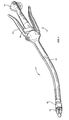
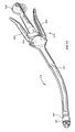
- Instrument 10 includes elongate body portion 12 and handle section 14.
- Handle section 14 includes anvil adjustment member 16, lever lockout or safety member 18 and fastener firing levers 20.
- Fastener head portion 22 and anvil member24 are disposed at the distal end of body portion 12.
- the materials utilized in the components of the surgical instrument of the present invention generally include such materials as polycarbonate for housing sections and related components, and stainless steel for such components which transmit forces.
- One preferred polycarbonate material is LEXAN® brand polycarbonate available from General Electric Company. However, equivalent alternative materials will readily come to the mind of those skilled in the art.
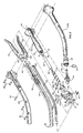
- Instrument 10 includes body or housing half sections 12a and 12b which are preferably molded and joined together by suitable fastening means such as rivets 28, or the like.
- elongated member 30 is slidably mounted within body portion 12, preferably by being securely mounted to helical cam member 32 by any suitable means such as, for example, welding or the like.
- Helical cam member 32 is slidably mounted within anvil adjustment member 16 by way of bushing 34 which is securely mounted in open end 36 of anvil adjustment member 16.
- Friction member 93 is disposed adjacent anvil adjustment member 16 to prevent relatively free rotation of the anvil adjustment member.
- both the mounting of bushing 34 and the camming of helical cam 32 is accomplished by compound pin 38 which has central portion 38a and extending portions 38b and 38c which are of reduced diameter. Portions 38a and 38b are press fitted into bores 40 and 42, respectively, located on bushing 34 and anvil adjustment member 16, respectively. Lower extending portion 38c serves as a camming pin and fits within the helical groove formed on the surface of helical cam 32.
- Anvil approximation indicator member 46 has extended portion 48 and is press fitted into proximal portion 50 of helical cam 32. Cap 51 is attached to proximal end 52 of anvil approximation indicator member 46.
- Cap 51 is preferably a colored piece which is easily visible through opening 54 formed near the proximal end of anvil adjustment member 16 to provide indication to the user when the anvil member is in the proper position for firing of the instrument.
- the distal end of elongated member 30 is provided with means to retain anvil member 24, which will be described in more detail below.
- the fastener firing mechanism of instrument 10 includes fastener firing member 56 which is slidably mounted within body portion 12 preferably such that fastener firing member 56 is disposed around elongated member 30.
- Fastener firing member 56 is preferably biased in a proximal direction by suitable biasing means such as spring 58.
- Fastener firing levers 20 are pivotably mounted to body portion 12 and have extended portions 60 which cross over each other in scissor-like fashion.
- Bearing block 62 is mounted on fastener firing member 56, for example, being held between flexible finger portions 64 and raised portions 66 which are formed in the side walls of fastener firing member 56, as best illustrated in Figs. 3 and 4.
- Fastener firing member 56 has bearing surfaces such as tabs 68 formed at the distal portion which serve to urge a pusher member within fastener head portion 22 in a distal direction in order to eject surgical fasteners 69, such as stainless steel or titanium staples, from fastener head portion 22.
- lever lockout member 18 is preferably spring biased to the locked out position by spring 67 in slot 91.
- Lever lockout member 18 is preferably spring biased to the locked out position by spring 67 in slot 91.
- Each of these lockout members are preferably mounted on instrument 10 in such a manner that they are fixed relative to each other and upon pivoting of lever lockout member 18, elongate member lockout member 70 also pivots.
- elongate member lockout member 70 has shoulder portions 73 and 75 formed therein as well as inwardly extending tab 79. The function of each of these portions of elongate member lockout member 70 will be described in further detail later herein.
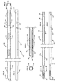
- fastener firing member 56 is shown as preferably being a generally U-shaped member formed from material which can transmit forces effectively and reliably such as stainless steel.
- Fastener firing member 56 has side walls 72 and 74 which are connected by web 76.
- fastener firing member 56 has extended portions or flexible bands 72a and 74a which are preferably formed integrally with walls 72 and 74, respectively.
- Band 72a is shorter than band 74a.
- the difference in the length of the two bands corresponds to the amount of curvature of body portion 12 so that when fastener firing member 56 is mounted in body portion 12, the surfaces of tabs 68 form a plane parallel with the surface of the fastener pusher member (not shown).
- elongated member 30 is shown as a U-shaped member, similar to fastener firing member 56.
- Elongated member 30 has side walls 78 and 80 which are joined by web 82.
- the cross-section dimensions of elongated member 30 are preferably such that elongated member 30 readily fits within fastener firing member 56. This arrangement is desirable so that elongated member 30 and fastener firing member 56 can slide independent of each other.
- elongated member 30 must also be formed to fit within the curved contour of body portion 12. To accomplish this curvature, elongated member 30 has extended portions or flexible bands 78a and 80a which are preferably formed integrally with walls 78 and 80, respectively.
- bands 78a and 80a of elongated member 30 are of different length.
- Elongated member 30 terminates at a distal end in a pair of opposed anvil retaining portions 84 and 86.
- structure can be provided within body portion 12 (see 320 in Fig. 15) that serves to retain the side walls and bands of both elongated member 30 and fastener firing member 56.
- Such structure can be of unitary construction and have grooves to direct longitudinal movement of the channels and bands.
- one or more seals can be disposed within body portion 12 to prevent the flow of gases therethrough.
- anvil retaining portions 84 and 86 are preferably semi-circular in shape as best illustrated in the cross-section view of Fig. 8.
- anvil retaining portions 84 and 86 are provided with flexible finger portions 88 and 90, respectively, each of which have a raised portion formed thereon, such as camming and retaining portions 92 and 94, respectively.
- Camming surfaces 96 and 98 formed by camming and retaining portions 92 and 94, respectively serve to cam flexible finger portions 88 and 90 radially outward upon insertion of the anvil into the distal end of instrument 10. Referring temporarily back to Fig. 2, once annular groove portion 100 of anvil shaft 102 passes between retaining portions 84 and 86, flexible finger portions 88 and 90 return toward their initial or at rest state so that retaining portions 92 and 94 seat in annular groove 100.
- Extended portions 78a and 80a of elongated member 30 are preferably bent until the ends of anvil retaining portions 84 and 86 are aligned and are then permanently joined together (as shown in Fig. 2), by suitable bonding techniques, such as, by welding.
- cut out portion 83 is formed to receive elongate member lockout member 70 when elongated member is properly positioned for firing the staples of instrument 10. As best illustrated in Figs. 6 and 7, cutout portion 83 is preferably formed through most of web 82 and continues partially up side wall 80.
- the user positions the tissue to be joined between anvil 24 and fastener head portion 22.
- Anvil adjustment member 16 is rotated to move elongated member 30 and anvil 24 proximally until the user sees approximation indicator 46 appear in opening 54 of anvil adjustment member 16.
- elongate member 30 acts as a tension member as it pulls anvil 24 into position adjacent fastener head portion 22.
- lockout 70 Prior to alignment of cut out 83 in elongate member 30 and extended portion 79 of elongate member lockout 70, lockout 70 is prevented from pivoting by contact between extended portion 79 and elongate member 30.
- lever lockout member 18 and elongate member lockout 70 are able to be pivoted by depressing, usually with the thumb, on lever lockout member 18.
- Members 18 and 70 can be interconnected by any suitable means, i.e., protrusion from one member entering a recess in the other.
- fastener firing member 56 acts as a compression member as it ejects fasteners 69.
- FIG. 14-18 a first embodiment of the present invention,shown as instrument 210, will now be described.
- components of the instrument of Figs. 14-18 which are similar or identical to those of the embodiment for Figs. 1-13 have been labelled by adding 200 to the reference numerals of the earlier embodiment.
- anvil shaft 102 of Fig. 2 corresponds to anvil shaft 302 of Fig. 15.
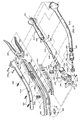
- instrument 210 includes insert guide 320 which is preferably molded of a polycarbonate material such as LEXAN® available from the General Electric Company.
- Insert guide 320 is preferably molded to conform to the curvature of housing half sections 212a and 212b so as to provide structural support for elongate member 230 and fastener firing member 256.
- insert guide 320 is illustrated in a partially cut away section to show the guide tracks which receive elongate member 230 and fastener firing member 256 therein.
- outer guide tracks 322 are molded to receive sidewalls 272 and 274 therein and inner guide tracks 324.are formed to receive side walls 78 and 80 of elongate member 30 therein. Insert guide 320 thereby provides structural support upon longitudinal motion of either elongate member 230 or fastener firing member 256, particularly at the point of curvature thereof. Insert guide 320 effectively reduces possible force transmission losses upon operation of instrument 210.
- seal half sections 326a and 326b are formed to fit around notches formed on insert guide 320.
- Seal half sections 326a and 326b are preferably molded of a hard rubber material which is molded to conform with the inner dimensions of housing half sections 212a and 212b. Additionally, seal half sections 326a and 326b are molded to fit over elongate member 230 and fastener firing member 256 so as to form a seal between the internal section of the instrument 210 which is distal of the seal half sections 326a and 326b and the internal portions of instrument 210 which are proximal of seal half sections 326a and 326b so as to inhibit the passage of gases thereby.
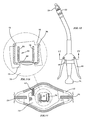
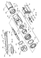
- An adjusting member such as collar 328 is mounted between the distal end of housing 212 and the proximal end of fastener head portion assembly 222.
- Collar 328 has ratchet teeth 330 formed on an inner surface thereof at the proximal end. Ratchet teeth 330 cooperate with ratchet teeth 332 formed on the distal end of housing half sections 212a and 212b. Ratchet teeth 330 and 332 interact to provide for rotational advancement of collar 328 in a single direction.
- collar 328 Also formed on collar 328 are camming surfaces 334 and 336 which interact with camming surfaces 338 and 340 formed at the proximal end of fastener head portion 222.
- a purpose of collar 328 is to provide for post instrument assembly adjustment of the relative longitudinal positioning of fastener head portion assembly 222 with respect to the distal end of body portion 212. This adjustment capability is important so that instrument 210 may be calibrated to insure the proper positioning of anvil member 224 when cap 251 of anvil approximation indicator member 246 is positioned within opening 254 so as to indicate that instrument 210 is ready for firing of surgical staples 269.
- collar member 328 may be fixedly secured to the distal end of body portion 212 so that collar 328 is not permitted to rotate with respect thereto. This attachment may be accomplished by known suitable means such as, for example, bonding and/or by the use of a fastener such as a screw or a pin.
- Pusher back 342 is provided with longitudinally extending portions 344 which are configured to fit inside of knife ring 346 and are preferably sized to abut against a surface portion, such as cut ring 345, of anvil 224 upon firing of instrument 210.
- portions 344 of pusher back 342 contact a portion of anvil 224, pusher fingers 352 are prevented from travelling further, thereby limiting the degree to which surgical staples 269 may be crimped against anvil 224.
- elongate member 230 has tip 354 formed at the distal end to facilitate puncturing of tissue as desired by the user of instrument 210.
- Tip 354 is preferably sharp and formed by known methods such as, for example, grinding with suitable abrasives.
- Tip 354 is formed such that a hollow passageway or opening 356 is formed which passes longitudinally through the distal end portion of elongate member 230.
- Opening 356 on elongate member 230 is preferably sized so that it can receive shaft 302 of anvil 224 so that anvil 224 may be retained by the distal end portion of elongate member 230 in a similar manner as set forth above for elongate member 30 and anvil 24 for the embodiment of Figs. 1-13.
- a protective cover is provided, such as cover 358 which is preferably formed of a deformable elastomeric material. Cover 358 is provided with raised portions 360 which correspond to bores 362 formed on elongate member 230 proximal of tip 354.
- cover 358 In use, when elongate member 230 is extended past head portion assembly 222, cover 358 deflects upon contact with tissue to expose tip 354. After tip 354 and cover 358 pass through the tissue, cover 358 returns to a position which protects tip 354, thereby providing means for preventing inadvertent trauma by tip 354 to surrounding tissue.
- instrument 210 The operation of instrument 210 is similar to that of instrument 10 except as noted hereinabove. Accordingly, no separate description of the operation of instrument 210 is provided.
Claims (17)
- Ein chirurgisches Instrument (210) zum Anbringen von zumindest einer kreisförmigen Anordnung von Verschlüssen (269), mit:gekennzeichnet durcheinem Gehäuse, das einen proximalen und einen distalen Endabschnitt aufweist;einem länglichen Schaft (212), der sich von dem distalen Endabschnitt des Gehäuses erstreckt, wobei der Schaft einen proximalen und einen distalen Endabschnitt aufweist;einem Verschluss-tragenden Magazin (222), das an dem distalen Endabschnitt des Schafts angeordnet ist;einem Ambosselement (224), das betriebsmäßig benachbart dem Verschluss-tragenden Magazin angeordnet ist, wobei das Ambosselement zwischen einer Position beabstandet von dem Verschluss-tragenden Magazin und einer angenäherten Position benachbart einem Einstellelement (216) bewegbar ist, das derart betätigbar ist, um den Amboss zwischen der beabstandeten und der angenäherten Position zu bewegen;ein Einstellelement (328), das betriebsmäßig mit dem Verschluss-tragenden Magazin im Zusammenhang steht, um die Längsposition des Verschluss-tragenden Magazins relativ zu dem distalen Ende des Schafts zu kalibrieren.
- Ein chirurgisches Instrument nach Anspruch 1, wobei das Einstellelement zumindest eine Verschiebeoberfläche (334, 336) umfasst, die betriebsmäßig dem Verschluss-tragenden Magazin zugeordnet ist.
- Ein chirurgisches Instrument nach Anspruch 2, wobei das Verschluss-tragende Magazin zumindest eine Verschiebeoberfläche (338, 340) umfasst, die betriebsmäßig der zumindest einen Verschiebeoberfläche des Einstellelements zugeordnet ist.
- Ein chirurgisches Instrument nach Anspruch 1, 2 oder 3, wobei das Einstellelement ein drehbares Hülsenelement ist.
- Ein chirurgisches Instrument nach Anspruch 4, wobei das Hülsenelement darauf angeordnete stufenweise Abschnitte umfasst, die derart ausgebildet sind, um stufenweise eine Bewegung der Verschiebeoberfläche des Hülsenelements im Anschluss an eine Bewegung des Hülsenelements relativ zu dem distalen Ende des länglichen Schafts zu vereinfachen.
- Ein chirurgisches Instrument nach Anspruch 5, wobei die Stufenabschnitte des Hülsenelements derart ausgebildet sind, um eine Bewegung des Hülsenelements in eine einzige Richtung zu vereinfachen.
- Ein chirurgisches Instrument nach Anspruch 5 oder 6, wobei die Stufenabschnitte des Hülsenelements eine Mehrzahl von Ratschenzähnen (330) umfasst, die betriebsmäßig zumindest einem Zahnabschnitt (332), der auf dem länglichen Schaft gebildet ist, zugeordnet sind.
- Ein chirurgisches Instrument nach einem der vorhergehenden Ansprüche, des weiteren mit einem länglichen Ambosshalteelement (230), das hin und her innerhalb des Verschluss-tragenden Magazins bewegbar ist.
- Ein chirurgisches Instrument nach Anspruch 8, wobei das längliche Ambosshalteelement einen hohlförmigen distalen Abschnitt aufweist.
- Ein chirurgisches Instrument nach Anspruch 9, wobei der hohlförmige distale Abschnitt eine scharfe Spitze (354) an einem distalen Ende des Halteelements bildet.
- Ein chirurgisches Instrument nach einem der Ansprüche 1 bis 7, des weiteren mit einem länglichen Ambosshalteelement (230), das innerhalb des Verschluss-tragenden Magazins hin und her bewegbar ist, und das einen hohlförmigen distalen Abschnitt bestimmt, der eine Spitze (354) an einem distalen Ende desselben bildet; und
wobei das Ambosselement zum lösbaren Befestigen des länglichen Ambosshalteelements ausgebildet ist. - Ein chirurgisches Instrument nach einem der Ansprüche 1 bis 11, wobei das Einstellelement zwischen dem distalen Endabschnitt des länglichen Schafts und einem proximalen Ende des Verschluss-tragenden Magazins angeordnet ist.
- Ein chirurgisches Instrument nach einem der Ansprüche 8 bis 11, des weiteren mit einem elastisch ausgebildeten Abdeckelement (358), das mit dem länglichen Ambosshalteelement verbunden ist und um die Spitze angeordnet ist.
- Ein chirurgisches Instrument nach Anspruch 13, wobei das elastisch ausgebildete Abdeckelement zumindest teilweise aus einem Elastomer gebildet ist.
- Ein chirurgisches Instrument nach einem der vorhergehenden Ansprüche, wobei das Verschluss-tragende Magazin ein Gehäuse, eine Mehrzahl von chirurgischen Verschlüssen, die innerhalb des Magazingehäuses angeordnet sind, ein Schubelement (352), das betriebsmäßig den chirurgischen Verschlüssen zugeordnet ist, ein Messerelement (346), das innerhalb des Magazingehäuses angeordnet ist, und ein Verschlusscrimpbegrenzungselement (342), das innerhalb des Magazingehäuses angeordnet ist, um die Verschlüsse vor einem übermäßigen Crimpen gegen das Ambosselement zu schützen, umfasst.
- Ein chirurgisches Instrument nach Anspruch 15, wobei das Verschlusscrimpbegrenzungselement einen Grundkörper (342) mit einem hiervon erstreckenden Längsabschnitt (344) umfasst, der betriebsmäßig dem Ambosselement zugeordnet ist, um das Crimpen der chirurgischen Verschlüsse nach Feuern des Instruments zu begrenzen.
- Ein chirurgisches Instrument nach Anspruch 15, wobei das Verschlusscrimpbegrenzungselement einen Grundkörper (342) mit einer Mehrzahl von sich in Längsrichtung erstreckenden Fingerabschnitten (344) umfasst, die von diesem überstehen und die betriebsmäßig dem Ambosselement zugeordnet sind, um das Crimpen der chirurgischen Verschlüsse nach Feuern des Instruments zu begrenzen.
Applications Claiming Priority (3)
| Application Number | Priority Date | Filing Date | Title |
|---|---|---|---|
| US24951294A | 1994-05-26 | 1994-05-26 | |
| US249512 | 1994-05-26 | ||
| EP95107521A EP0695532B1 (de) | 1994-05-26 | 1995-05-17 | Vorrichtung für kreisformige Anastomose |
Related Parent Applications (1)
| Application Number | Title | Priority Date | Filing Date |
|---|---|---|---|
| EP95107521A Division EP0695532B1 (de) | 1994-05-26 | 1995-05-17 | Vorrichtung für kreisformige Anastomose |
Publications (2)
| Publication Number | Publication Date |
|---|---|
| EP1175869A1 EP1175869A1 (de) | 2002-01-30 |
| EP1175869B1 true EP1175869B1 (de) | 2003-10-15 |
Family
ID=22943775
Family Applications (4)
| Application Number | Title | Priority Date | Filing Date |
|---|---|---|---|
| EP95107521A Expired - Lifetime EP0695532B1 (de) | 1994-05-26 | 1995-05-17 | Vorrichtung für kreisformige Anastomose |
| EP01126595A Expired - Lifetime EP1175869B1 (de) | 1994-05-26 | 1995-05-17 | Vorrichtung für kreisformige Anastomose |
| EP01126594A Expired - Lifetime EP1175868B1 (de) | 1994-05-26 | 1995-05-17 | Vorrichtung für kreisformige Anastomose |
| EP03016597A Expired - Lifetime EP1354560B1 (de) | 1994-05-26 | 1995-05-17 | Vorrichtung für kreisformige Anastomose |
Family Applications Before (1)
| Application Number | Title | Priority Date | Filing Date |
|---|---|---|---|
| EP95107521A Expired - Lifetime EP0695532B1 (de) | 1994-05-26 | 1995-05-17 | Vorrichtung für kreisformige Anastomose |
Family Applications After (2)
| Application Number | Title | Priority Date | Filing Date |
|---|---|---|---|
| EP01126594A Expired - Lifetime EP1175868B1 (de) | 1994-05-26 | 1995-05-17 | Vorrichtung für kreisformige Anastomose |
| EP03016597A Expired - Lifetime EP1354560B1 (de) | 1994-05-26 | 1995-05-17 | Vorrichtung für kreisformige Anastomose |
Country Status (4)
| Country | Link |
|---|---|
| EP (4) | EP0695532B1 (de) |
| CA (1) | CA2147800C (de) |
| DE (4) | DE69527680T2 (de) |
| ES (4) | ES2326523T3 (de) |
Cited By (1)
| Publication number | Priority date | Publication date | Assignee | Title |
|---|---|---|---|---|
| US10842524B2 (en) | 2014-02-14 | 2020-11-24 | Ethicon Llc | Lockout mechanisms for surgical devices |
Families Citing this family (155)
| Publication number | Priority date | Publication date | Assignee | Title |
|---|---|---|---|---|
| US6454702B1 (en) | 1999-10-14 | 2002-09-24 | Scimed Life Systems, Inc. | Endoscope and endoscopic instrument system having reduced backlash when moving the endoscopic instrument within a working channel of the endoscope |
| GB0818101D0 (en) | 2008-10-03 | 2008-11-05 | Femcare Nikomed Ltd | Applicator for surgical clips |
| US8231042B2 (en) | 2008-11-06 | 2012-07-31 | Tyco Healthcare Group Lp | Surgical stapler |
| US8281974B2 (en) | 2009-01-14 | 2012-10-09 | Tyco Healthcare, Group LP | Surgical stapler with suture locator |
| US8146790B2 (en) | 2009-07-11 | 2012-04-03 | Tyco Healthcare Group Lp | Surgical instrument with safety mechanism |
| US8267301B2 (en) * | 2009-08-19 | 2012-09-18 | Tyco Healthcare Group Lp | Surgical stapler |
| US8708212B2 (en) | 2011-10-18 | 2014-04-29 | Covidien Lp | Tilt top anvil with torsion spring |
| US9016547B2 (en) | 2011-10-26 | 2015-04-28 | Covidien Lp | EEA tilt top anvil with ratchet/locking mechanism |
| US9010605B2 (en) | 2012-01-12 | 2015-04-21 | Covidien Lp | Sliding sleeve for circular stapling instrument reloads |
| US9022274B2 (en) | 2012-02-15 | 2015-05-05 | Covidien Lp | Circular stapler with increased lumen diameter |
| US9351734B2 (en) | 2012-06-19 | 2016-05-31 | Covidien Lp | Spring loaded anvil retainer |
| US10213205B2 (en) | 2012-07-06 | 2019-02-26 | Covidien Lp | T-slot tilt anvil for circular stapling instrument |
| US9675359B2 (en) | 2012-10-10 | 2017-06-13 | Covidien Lp | Surgical instrument with preload assembly |
| US9572572B2 (en) | 2012-11-09 | 2017-02-21 | Covidien Lp | Circular stapler mechanical lockout |
| US9351724B2 (en) | 2013-01-11 | 2016-05-31 | Covidien Lp | Circular stapling instrument |
| US9592056B2 (en) | 2013-03-14 | 2017-03-14 | Covidien Lp | Powered stapling apparatus |
| CN104042292A (zh) | 2013-03-15 | 2014-09-17 | 柯惠Lp公司 | 包括可重复利用的组件的手术吻合装置 |
| CN103126738B (zh) * | 2013-03-22 | 2015-07-15 | 常州华森医疗器械有限公司 | 活动头可吸收生物钉带针肛肠、胃肠吻合器 |
| US9532780B2 (en) | 2013-06-12 | 2017-01-03 | Covidien Lp | EEA anvil snap ring activator |
| US9668740B2 (en) | 2013-06-14 | 2017-06-06 | Covidien Lp | Anvil assembly with sliding sleeve |
| WO2014201608A1 (en) | 2013-06-17 | 2014-12-24 | Covidien Lp | Surgical instrument with lockout mechanism |
| US9750503B2 (en) | 2013-07-11 | 2017-09-05 | Covidien Lp | Methods and devices for performing a surgical anastomosis |
| US9693773B2 (en) | 2013-09-11 | 2017-07-04 | Covidien Lp | Anvil assembly with sliding sleeve |
| US9517070B2 (en) | 2013-11-13 | 2016-12-13 | Covidien Lp | Anvil assembly and delivery system |
| US9554802B2 (en) | 2013-11-13 | 2017-01-31 | Covidien Lp | Anvil assembly with frangible retaining member |
| US9913643B2 (en) | 2014-05-09 | 2018-03-13 | Covidien Lp | Interlock assemblies for replaceable loading unit |
| CN106456166B (zh) | 2014-06-12 | 2019-11-01 | 柯惠有限合伙公司 | 外科缝合器 |
| US9867619B2 (en) | 2014-06-24 | 2018-01-16 | Covidien Lp | System for delivering an anvil assembly to a surgical site |
| US9861367B2 (en) | 2014-06-24 | 2018-01-09 | Covidien Lp | Anvil assembly delivery systems |
| US10405864B2 (en) | 2014-07-04 | 2019-09-10 | Covidien Lp | Loading unit with shipping member for surgical stapling device |
| US9757133B2 (en) | 2014-07-09 | 2017-09-12 | Covidien Lp | Methods and devices for performing a surgical anastomosis |
| CN104367360B (zh) * | 2014-10-22 | 2016-09-21 | 重庆康美唯外科器械有限公司 | 一种医用吻合器及其保险指示系统 |
| US10085744B2 (en) | 2014-12-08 | 2018-10-02 | Covidien Lp | Loading unit attachment band for surgical stapling instrument |
| US9855045B2 (en) | 2014-12-09 | 2018-01-02 | Covidien Lp | Anvil assembly delivery system |
| WO2016090600A1 (en) | 2014-12-11 | 2016-06-16 | Covidien Lp | Stapler with auto-matic lockout mechanism |
| EP3229707A1 (de) | 2014-12-11 | 2017-10-18 | Covidien LP | Chirurgische klammerladeeinheit |
| JP6518766B2 (ja) | 2014-12-17 | 2019-05-22 | コヴィディエン リミテッド パートナーシップ | ファイアリング表示体を有する外科用ステープリングデバイス |
| US10039549B2 (en) | 2015-01-07 | 2018-08-07 | Covidien Lp | Loading unit retention clip for surgical stapling instrument |
| US10117656B2 (en) | 2015-01-07 | 2018-11-06 | Covidien Lp | Loading unit locking collar |
| US10022126B2 (en) | 2015-01-07 | 2018-07-17 | Covidien Lp | Loading unit locking collar |
| CN105982710A (zh) * | 2015-01-28 | 2016-10-05 | 常州安康医疗器械有限公司 | 一种新型圆形吻合器的无极变速锁紧机构 |
| WO2016127433A1 (en) | 2015-02-15 | 2016-08-18 | Covidien Lp | Surgical stapling device with firing indicator of unitary construction |
| US10881408B2 (en) | 2015-04-22 | 2021-01-05 | Covidien Lp | Interlock assembly for replaceable loading units |
| US10426480B2 (en) | 2015-04-29 | 2019-10-01 | Covidien Lp | Cutting ring assembly with rigid cutting member |
| US9987001B2 (en) | 2015-06-12 | 2018-06-05 | Covidien Lp | Surgical anastomosis apparatus |
| US9974536B2 (en) | 2015-07-02 | 2018-05-22 | Covidien Lp | Anvil assemblies and delivery systems |
| US10111668B2 (en) | 2015-07-02 | 2018-10-30 | Covidien Lp | Anvil assembly with snap backup ring |
| US10117655B2 (en) | 2015-07-22 | 2018-11-06 | Covidien Lp | Loading unit locking band for surgical stapling instrument |
| US10085756B2 (en) | 2015-07-24 | 2018-10-02 | Covidien Lp | Anvil assembly and anvil assembly delivery system |
| US10117675B2 (en) | 2015-07-28 | 2018-11-06 | Covidien Lp | Trocar tip protector |
| US9980730B2 (en) | 2015-09-21 | 2018-05-29 | Covidien Lp | Loading unit locking collar with rotational actuated release |
| US10111684B2 (en) | 2015-09-25 | 2018-10-30 | Covidien Lp | Adapter assembly including a removable trocar assembly |
| US10542992B2 (en) | 2015-10-19 | 2020-01-28 | Covidien Lp | Loading unit with stretchable bushing |
| WO2017066918A1 (en) | 2015-10-20 | 2017-04-27 | Covidien Lp | Circular stapler with tissue gap indicator assembly |
| EP3364886B1 (de) | 2015-10-21 | 2021-12-01 | Covidien LP | Ringförmiges messer für chirurgisches klammergerät |
| US10512466B2 (en) | 2015-11-05 | 2019-12-24 | Covidien Lp | Adapter assembly for surgical device |
| CN108289683B (zh) | 2015-11-13 | 2021-06-25 | 柯惠有限合伙公司 | 具有可听指示器机构的圆形钉合器 |
| CN105310747B (zh) * | 2015-12-05 | 2017-09-12 | 北京天钥医疗器械有限公司 | 一种带凹形座锁止机构的包皮环切吻合器 |
| ES2821891T3 (es) | 2015-12-07 | 2021-04-28 | Covidien Lp | Conjunto de yunque y sistema de suministro |
| US10390835B2 (en) | 2015-12-10 | 2019-08-27 | Covidien Lp | Surgical fastener apparatus with linear position sensor |
| US10524797B2 (en) | 2016-01-13 | 2020-01-07 | Covidien Lp | Adapter assembly including a removable trocar assembly |
| WO2017132932A1 (en) | 2016-02-04 | 2017-08-10 | Covidien Lp | Circular stapler with visual indicator mechanism |
| US10603042B2 (en) | 2016-02-10 | 2020-03-31 | Covidien Lp | Flexible circular stapler |
| US10595871B2 (en) | 2016-05-10 | 2020-03-24 | Covidien Lp | Insertion instrument, adapter assemblies and protector assemblies for a flexible circular stapler |
| US11141162B2 (en) | 2016-07-08 | 2021-10-12 | Covidien Lp | Loading unit locking collar with linearly actuated release |
| US11452522B2 (en) | 2016-08-15 | 2022-09-27 | Covidien Lp | Circular stapling device with articulating anvil retainer assembly |
| US10426470B2 (en) | 2016-11-04 | 2019-10-01 | Covidien Lp | Stapling device with releasable knife carrier |
| US10499922B2 (en) | 2016-11-04 | 2019-12-10 | Covidien Lp | Stapling device with self-releasing knife carrier pusher |
| US11241232B2 (en) | 2017-01-24 | 2022-02-08 | Covidien Lp | Surgical stapling device with resettable anvil assembly |
| EP3639755B1 (de) | 2017-01-25 | 2021-06-23 | Covidien LP | Kreisförmige klammervorrichtung |
| US10542993B2 (en) | 2017-02-24 | 2020-01-28 | Covidien Lp | Anvil assembly of circular stapling device including alignment splines |
| EP3592252B1 (de) | 2017-03-09 | 2023-10-25 | Covidien LP | Endeffektoranordnung für kreisförmiges klammergerät |
| WO2018161314A1 (en) | 2017-03-09 | 2018-09-13 | Covidien Lp | Surgical stapling device with audible indicator mechanism |
| US10342534B2 (en) | 2017-03-23 | 2019-07-09 | Covidien Lp | Surgical stapling device with releasable knife carrier |
| WO2018170831A1 (en) | 2017-03-23 | 2018-09-27 | Covidien Lp | Circular stapling device with alignment splines |
| US10881409B2 (en) | 2017-05-02 | 2021-01-05 | Covidien Lp | Rotation assembly for a surgical device |
| US10932784B2 (en) | 2017-06-09 | 2021-03-02 | Covidien Lp | Handheld electromechanical surgical system |
| US11596400B2 (en) | 2017-06-09 | 2023-03-07 | Covidien Lp | Handheld electromechanical surgical system |
| US11045199B2 (en) | 2017-06-09 | 2021-06-29 | Covidien Lp | Handheld electromechanical surgical system |
| US10987107B2 (en) | 2017-07-05 | 2021-04-27 | Covidien Lp | Surgical stapling device |
| US11090054B2 (en) | 2017-08-07 | 2021-08-17 | Covidien Lp | Stapling device with resettable tilt anvil assembly |
| US10828026B2 (en) | 2017-08-08 | 2020-11-10 | Covidien Lp | Tiltable anvil assembly |
| US10695069B2 (en) | 2017-08-23 | 2020-06-30 | Covidien Lp | Circular stapling device with offset spline tip |
| US11234703B2 (en) | 2017-09-01 | 2022-02-01 | Covidien Lp | Circular stapling device with position ribs |
| US11324507B2 (en) | 2017-11-03 | 2022-05-10 | Covidien Lp | Device and method for attachment of a stomal sleeve |
| US11497501B2 (en) | 2018-03-26 | 2022-11-15 | Covidien Lp | Circular stapling device with A-frame splines |
| US10952734B2 (en) | 2018-04-23 | 2021-03-23 | Covidien Lp | Stapling device with cut ring biasing member |
| US11197676B2 (en) | 2018-06-28 | 2021-12-14 | Covidien Lp | Tie-down method for anvil assembly delivery system |
| US11241234B2 (en) | 2018-08-14 | 2022-02-08 | Covidien Lp | Anvil assembly with self-retaining backup member |
| CN112584780A (zh) | 2018-08-24 | 2021-03-30 | 柯惠有限合伙公司 | 电动圆形钉合装置 |
| US10973544B2 (en) | 2018-10-02 | 2021-04-13 | Covidien Lp | Retaining mechanism for trocar assembly |
| US11141163B2 (en) | 2018-10-04 | 2021-10-12 | Covidien Lp | Circular stapling device with anvil rotation locking structure |
| US11065005B2 (en) | 2018-11-07 | 2021-07-20 | Covidien Lp | Reload assembly for a circular stapling device |
| US11147561B2 (en) | 2018-11-28 | 2021-10-19 | Covidien Lp | Reload assembly for a circular stapling device |
| US11389263B2 (en) | 2018-12-13 | 2022-07-19 | Covidien Lp | Lockout mechanisms for surgical instruments |
| US11166728B2 (en) | 2019-02-08 | 2021-11-09 | Covidien Lp | Reload assembly for a circular stapling device |
| US11529144B2 (en) | 2019-02-22 | 2022-12-20 | Covidien Lp | Encapsulated plug assembly for electromechanical surgical devices |
| US11547411B2 (en) | 2019-02-22 | 2023-01-10 | Covidien Lp | Anastomosis wound protector |
| US11337701B2 (en) | 2019-03-01 | 2022-05-24 | Covidien Lp | Devices and methods for assembling adapter assemblies |
| US11331782B2 (en) | 2019-03-01 | 2022-05-17 | Covidien Lp | Reload assembly for a circular stapling device |
| US11457921B2 (en) | 2019-03-26 | 2022-10-04 | Covidien Lp | Anvil assembly for surgical stapling instrument |
| US11596410B2 (en) | 2019-04-05 | 2023-03-07 | Covidien Lp | Surgical stapling device |
| US11534164B2 (en) | 2019-04-05 | 2022-12-27 | Covidien Lp | Strain gauge stabilization in a surgical device |
| US11344330B2 (en) | 2019-04-16 | 2022-05-31 | Covidien Lp | Trocar assemblies for adapter assemblies for surgical stapling instruments |
| US11419631B2 (en) | 2019-04-16 | 2022-08-23 | Covidien Lp | Trocar assemblies for adapter assemblies for surgical stapling instruments |
| US11660116B2 (en) | 2019-04-16 | 2023-05-30 | Covidien Lp | Trocar assemblies for adapter assemblies for surgical stapling instruments |
| US11317945B2 (en) | 2019-04-16 | 2022-05-03 | Covidien Lp | Trocar assemblies for adapter assemblies for surgical stapling instruments |
| US11839378B2 (en) | 2019-04-19 | 2023-12-12 | Covidien Lp | Circular stapling instruments |
| US11399838B2 (en) | 2019-04-22 | 2022-08-02 | Covidien Lp | Reload assembly for circular stapling devices |
| US11246599B2 (en) | 2019-04-25 | 2022-02-15 | Covidien Lp | End effector for circular stapling instrument |
| US11896233B2 (en) | 2019-05-31 | 2024-02-13 | Covidien Lp | Circular stapling device |
| US11690624B2 (en) | 2019-06-21 | 2023-07-04 | Covidien Lp | Reload assembly injection molded strain gauge |
| US11446035B2 (en) | 2019-06-24 | 2022-09-20 | Covidien Lp | Retaining mechanisms for trocar assemblies |
| US11123101B2 (en) | 2019-07-05 | 2021-09-21 | Covidien Lp | Retaining mechanisms for trocar assemblies |
| US11357509B2 (en) | 2019-07-11 | 2022-06-14 | Covidien Lp | Reload assembly for a circular stapling device |
| US11192227B2 (en) | 2019-07-16 | 2021-12-07 | Covidien Lp | Reload assembly for circular stapling devices |
| US11253255B2 (en) | 2019-07-26 | 2022-02-22 | Covidien Lp | Knife lockout wedge |
| US11464510B2 (en) | 2019-07-26 | 2022-10-11 | Covidien Lp | Reload assembly with knife carrier lockout |
| US11399825B2 (en) | 2019-10-28 | 2022-08-02 | Covidien Lp | Reload assembly with knife carrier lockout |
| US11553918B2 (en) | 2019-12-16 | 2023-01-17 | Covidien Lp | Reload assembly with knife carrier lockout |
| US11517317B2 (en) | 2020-01-06 | 2022-12-06 | Covidien Lp | Trocar release assemblies for a surgical stapler |
| US11730481B2 (en) | 2020-01-06 | 2023-08-22 | Covidien Lp | Assemblies for retaining a trocar assembly |
| US11911038B2 (en) | 2020-01-13 | 2024-02-27 | Covidien Lp | Cut optimization for excessive tissue conditions |
| US11523828B2 (en) | 2020-01-28 | 2022-12-13 | Covidien Lp | Sealed reload assembly for stapling device |
| US11622767B2 (en) | 2020-02-19 | 2023-04-11 | Covidien Lp | Sealed trocar assembly for stapling device |
| US11547438B2 (en) | 2020-02-24 | 2023-01-10 | Covidien Lp | Tip protector for ensuring trocar insertion |
| US11382630B2 (en) | 2020-02-25 | 2022-07-12 | Covidien Lp | Surgical stapling device with two part knife assembly |
| US11779343B2 (en) | 2020-02-26 | 2023-10-10 | Covidien Lp | Staple reload assembly with releasable knife |
| US11298152B2 (en) | 2020-02-28 | 2022-04-12 | Covidien Lp | Trocar retaining mechanism including band support |
| US11272998B2 (en) | 2020-03-04 | 2022-03-15 | Covidien Lp | Strain gage fixation in tension |
| US11426169B2 (en) | 2020-03-24 | 2022-08-30 | Covidien Lp | Retaining mechanisms for trocar assemblies |
| US11350939B2 (en) | 2020-03-24 | 2022-06-07 | Covidien Lp | Retaining mechanisms for trocar assemblies |
| US11426170B2 (en) | 2020-03-24 | 2022-08-30 | Covidien Lp | Retaining mechanisms for trocar assemblies |
| US11653925B2 (en) | 2020-05-21 | 2023-05-23 | Covidien Lp | Tissue relaxation monitoring for optimized tissue stapling |
| US11547405B2 (en) | 2020-05-22 | 2023-01-10 | Covidien Lp | Surgical stapling device |
| US11553921B2 (en) | 2020-07-15 | 2023-01-17 | Covidien Lp | Surgical stapling device with flexible shaft |
| US11547412B2 (en) | 2020-07-22 | 2023-01-10 | Covidien Lp | Surgical instruments and methods of assembly |
| US11877744B2 (en) | 2020-08-14 | 2024-01-23 | Covidien Lp | Low-cost powered stapler with end stop selection |
| US11627966B2 (en) | 2020-08-26 | 2023-04-18 | Covidien Lp | Surgical stapling device |
| US11801054B2 (en) | 2020-09-22 | 2023-10-31 | Covidien Lp | Surgical stapler with oval tool assembly |
| US11712509B2 (en) | 2020-10-02 | 2023-08-01 | Covidien Lp | Seal assembly for circular stapling instrument |
| US11627967B2 (en) | 2020-11-23 | 2023-04-18 | Covidien Lp | Trans-anastomotic insertion device |
| CN112890897B (zh) * | 2021-01-18 | 2022-11-15 | 江苏钱璟医疗器械有限公司 | 刀头可更换式点切吻合器 |
| US11877750B2 (en) | 2021-01-21 | 2024-01-23 | Covidien Lp | Surgical stapler with powered and manual functions |
| CN112674843B (zh) * | 2021-02-02 | 2021-10-26 | 山东省千佛山医院 | 局部弧切吻合器 |
| US11786241B2 (en) | 2021-02-16 | 2023-10-17 | Covidien Lp | Surgical stapling device including a hydraulic staple formation mechanism |
| US11553920B2 (en) | 2021-05-03 | 2023-01-17 | Covidien Lp | Trocar retainer assembly for surgical stapler |
| US11490894B1 (en) | 2021-05-12 | 2022-11-08 | Covidien Lp | Surgical device with grease filter |
| US11642131B2 (en) | 2021-05-17 | 2023-05-09 | Covidien Lp | Devices and methods for shortening a rectal stump during a lower anterior resection procedure |
| US11612400B2 (en) | 2021-05-24 | 2023-03-28 | Covidien Lp | Trocar assembly with bearing assembly for load sharing |
| US11737759B2 (en) | 2021-08-05 | 2023-08-29 | Covidien Lp | Surgical stapling device accommodating prolapsed tissue |
| US11819208B2 (en) | 2021-08-05 | 2023-11-21 | Covidien Lp | Handheld electromechanical surgical device with strain gauge drift detection |
| US11744592B2 (en) | 2021-08-05 | 2023-09-05 | Covidien Lp | Handheld electromechanical stapler with tissue thickness detection |
| US11883028B2 (en) | 2021-09-08 | 2024-01-30 | Covidien Lp | Systems and methods for post-operative anastomotic leak detection |
| US11717299B2 (en) | 2021-10-12 | 2023-08-08 | Covidien Lp | Surgical stapling device with probiotics |
Family Cites Families (20)
| Publication number | Priority date | Publication date | Assignee | Title |
|---|---|---|---|---|
| GB1121673A (en) * | 1965-08-26 | 1968-07-31 | N Isseldovatelsky Iex Khirurgi | Improvements in or relating to a surgical instrument for suturing hollow organs |
| US3593903A (en) * | 1968-07-12 | 1971-07-20 | Vnii Khirurgicheskoi Apparatur | Surgical instrument for suturing hollow organs in infants |
| US4603693A (en) | 1977-05-26 | 1986-08-05 | United States Surgical Corporation | Instrument for circular surgical stapling of hollow body organs and disposable cartridge therefor |
| US4319576A (en) * | 1980-02-26 | 1982-03-16 | Senco Products, Inc. | Intralumenal anastomosis surgical stapling instrument |
| US4606343A (en) * | 1980-08-18 | 1986-08-19 | United States Surgical Corporation | Self-powered surgical fastening instrument |
| US4351466A (en) | 1980-10-16 | 1982-09-28 | United States Surgical Corporation | Disposable instrument for surgical fastening |
| US4576167A (en) | 1981-09-03 | 1986-03-18 | United States Surgical Corporation | Surgical stapler apparatus with curved shaft |
| US4485817A (en) * | 1982-05-28 | 1984-12-04 | United States Surgical Corporation | Surgical stapler apparatus with flexible shaft |
| AU5476486A (en) * | 1985-03-14 | 1986-09-18 | Hospital Products Ltd. | Surgical stapling instrument |
| US4776506A (en) * | 1986-11-13 | 1988-10-11 | United States Surgical Corporation | Surgical stapler apparatus |
| US5119983A (en) * | 1987-05-26 | 1992-06-09 | United States Surgical Corporation | Surgical stapler apparatus |
| US5005749A (en) | 1988-07-01 | 1991-04-09 | United States Surgical Corp. | Anastomosis surgical stapling instrument |
| US5104025A (en) | 1990-09-28 | 1992-04-14 | Ethicon, Inc. | Intraluminal anastomotic surgical stapler with detached anvil |
| US5104382A (en) * | 1991-01-15 | 1992-04-14 | Ethicon, Inc. | Trocar |
| US5152754A (en) * | 1991-02-15 | 1992-10-06 | Minnesota Mining And Manufacturing Company | Trocar |
| US5137198A (en) * | 1991-05-16 | 1992-08-11 | Ethicon, Inc. | Fast closure device for linear surgical stapling instrument |
| GR920100358A (el) * | 1991-08-23 | 1993-06-07 | Ethicon Inc | Οργανο συρραφής χειρουργικής αναστομώσεως. |
| DE69217808T2 (de) * | 1991-10-18 | 1997-07-24 | United States Surgical Corp | Gerät zum Anbringen von chirurgischen Befestigungen |
| US5271543A (en) * | 1992-02-07 | 1993-12-21 | Ethicon, Inc. | Surgical anastomosis stapling instrument with flexible support shaft and anvil adjusting mechanism |
| CA2107848C (en) * | 1992-10-09 | 2005-04-12 | Frank J. Viola | Surgical fastener applying apparatus |
-
1995
- 1995-04-25 CA CA002147800A patent/CA2147800C/en not_active Expired - Lifetime
- 1995-05-17 EP EP95107521A patent/EP0695532B1/de not_active Expired - Lifetime
- 1995-05-17 EP EP01126595A patent/EP1175869B1/de not_active Expired - Lifetime
- 1995-05-17 ES ES03016597T patent/ES2326523T3/es not_active Expired - Lifetime
- 1995-05-17 DE DE69527680T patent/DE69527680T2/de not_active Expired - Lifetime
- 1995-05-17 DE DE69531966T patent/DE69531966T2/de not_active Expired - Lifetime
- 1995-05-17 ES ES95107521T patent/ES2177591T3/es not_active Expired - Lifetime
- 1995-05-17 ES ES01126594T patent/ES2199198T3/es not_active Expired - Lifetime
- 1995-05-17 DE DE69531417T patent/DE69531417T2/de not_active Expired - Lifetime
- 1995-05-17 ES ES01126595T patent/ES2203574T3/es not_active Expired - Lifetime
- 1995-05-17 EP EP01126594A patent/EP1175868B1/de not_active Expired - Lifetime
- 1995-05-17 DE DE69535950T patent/DE69535950D1/de not_active Expired - Lifetime
- 1995-05-17 EP EP03016597A patent/EP1354560B1/de not_active Expired - Lifetime
Cited By (1)
| Publication number | Priority date | Publication date | Assignee | Title |
|---|---|---|---|---|
| US10842524B2 (en) | 2014-02-14 | 2020-11-24 | Ethicon Llc | Lockout mechanisms for surgical devices |
Also Published As
| Publication number | Publication date |
|---|---|
| EP1354560A2 (de) | 2003-10-22 |
| DE69531966T2 (de) | 2004-08-12 |
| DE69531417T2 (de) | 2004-04-15 |
| EP1354560A3 (de) | 2004-04-07 |
| DE69527680T2 (de) | 2003-04-10 |
| CA2147800C (en) | 2006-07-11 |
| EP1175868A3 (de) | 2002-03-13 |
| CA2147800A1 (en) | 1995-11-27 |
| EP0695532B1 (de) | 2002-08-07 |
| DE69531417D1 (de) | 2003-09-04 |
| ES2326523T3 (es) | 2009-10-14 |
| EP1354560B1 (de) | 2009-05-06 |
| EP1175868B1 (de) | 2003-07-30 |
| EP1175869A1 (de) | 2002-01-30 |
| ES2199198T3 (es) | 2004-02-16 |
| DE69535950D1 (de) | 2009-06-18 |
| EP0695532A2 (de) | 1996-02-07 |
| ES2177591T3 (es) | 2002-12-16 |
| DE69527680D1 (de) | 2002-09-12 |
| ES2203574T3 (es) | 2004-04-16 |
| EP0695532A3 (de) | 1996-03-06 |
| EP1175868A2 (de) | 2002-01-30 |
| DE69531966D1 (de) | 2003-11-20 |
Similar Documents
| Publication | Publication Date | Title |
|---|---|---|
| EP1175869B1 (de) | Vorrichtung für kreisformige Anastomose | |
| US5685474A (en) | Tactile indicator for surgical instrument | |
| EP0656189B1 (de) | Vorrichtung für kreisförmige Anastomose | |
| EP2286731B1 (de) | Chirurgische Klammervorrichtung | |
| US8348122B2 (en) | Surgical stapling device | |
| EP2813187B1 (de) | EEA-Prallsprengringaktivator | |
| CA2530141C (en) | Circular anastomosis device | |
| CA2467866C (en) | Circular anastomosis device | |
| CA2515565C (en) | Circular anastomosis device |
Legal Events
| Date | Code | Title | Description |
|---|---|---|---|
| PUAI | Public reference made under article 153(3) epc to a published international application that has entered the european phase |
Free format text: ORIGINAL CODE: 0009012 |
|
| 17P | Request for examination filed |
Effective date: 20011116 |
|
| AC | Divisional application: reference to earlier application |
Ref document number: 695532 Country of ref document: EP |
|
| AK | Designated contracting states |
Kind code of ref document: A1 Designated state(s): DE ES FR GB IT |
|
| RIN1 | Information on inventor provided before grant (corrected) |
Inventor name: ROBERTSON, JOHN CHARLES Inventor name: GERRY, STEPHEN W. Inventor name: FOWLER, DAVID N. Inventor name: GALLAGHER, RICHARD J. Inventor name: SCHNUT, ROBERT H. |
|
| AKX | Designation fees paid |
Free format text: DE ES FR GB IT |
|
| 17Q | First examination report despatched |
Effective date: 20021008 |
|
| GRAH | Despatch of communication of intention to grant a patent |
Free format text: ORIGINAL CODE: EPIDOS IGRA |
|
| GRAS | Grant fee paid |
Free format text: ORIGINAL CODE: EPIDOSNIGR3 |
|
| GRAA | (expected) grant |
Free format text: ORIGINAL CODE: 0009210 |
|
| AC | Divisional application: reference to earlier application |
Ref document number: 0695532 Country of ref document: EP Kind code of ref document: P |
|
| AK | Designated contracting states |
Kind code of ref document: B1 Designated state(s): DE ES FR GB IT |
|
| REG | Reference to a national code |
Ref country code: GB Ref legal event code: FG4D |
|
| REF | Corresponds to: |
Ref document number: 69531966 Country of ref document: DE Date of ref document: 20031120 Kind code of ref document: P |
|
| REG | Reference to a national code |
Ref country code: ES Ref legal event code: FG2A Ref document number: 2203574 Country of ref document: ES Kind code of ref document: T3 |
|
| ET | Fr: translation filed | ||
| PLBE | No opposition filed within time limit |
Free format text: ORIGINAL CODE: 0009261 |
|
| STAA | Information on the status of an ep patent application or granted ep patent |
Free format text: STATUS: NO OPPOSITION FILED WITHIN TIME LIMIT |
|
| 26N | No opposition filed |
Effective date: 20040716 |
|
| PGFP | Annual fee paid to national office [announced via postgrant information from national office to epo] |
Ref country code: ES Payment date: 20120528 Year of fee payment: 18 |
|
| PGFP | Annual fee paid to national office [announced via postgrant information from national office to epo] |
Ref country code: IT Payment date: 20130524 Year of fee payment: 19 |
|
| PGFP | Annual fee paid to national office [announced via postgrant information from national office to epo] |
Ref country code: GB Payment date: 20140527 Year of fee payment: 20 |
|
| PGFP | Annual fee paid to national office [announced via postgrant information from national office to epo] |
Ref country code: DE Payment date: 20140529 Year of fee payment: 20 Ref country code: FR Payment date: 20140519 Year of fee payment: 20 |
|
| PG25 | Lapsed in a contracting state [announced via postgrant information from national office to epo] |
Ref country code: IT Free format text: LAPSE BECAUSE OF NON-PAYMENT OF DUE FEES Effective date: 20140517 |
|
| REG | Reference to a national code |
Ref country code: DE Ref legal event code: R071 Ref document number: 69531966 Country of ref document: DE |
|
| REG | Reference to a national code |
Ref country code: GB Ref legal event code: PE20 Expiry date: 20150516 |
|
| REG | Reference to a national code |
Ref country code: ES Ref legal event code: FD2A Effective date: 20150629 |
|
| PG25 | Lapsed in a contracting state [announced via postgrant information from national office to epo] |
Ref country code: GB Free format text: LAPSE BECAUSE OF EXPIRATION OF PROTECTION Effective date: 20150516 Ref country code: ES Free format text: LAPSE BECAUSE OF NON-PAYMENT OF DUE FEES Effective date: 20140518 |