EP1175861A1 - Badewannen-Haltevorrichtung - Google Patents
Badewannen-Haltevorrichtung Download PDFInfo
- Publication number
- EP1175861A1 EP1175861A1 EP01810727A EP01810727A EP1175861A1 EP 1175861 A1 EP1175861 A1 EP 1175861A1 EP 01810727 A EP01810727 A EP 01810727A EP 01810727 A EP01810727 A EP 01810727A EP 1175861 A1 EP1175861 A1 EP 1175861A1
- Authority
- EP
- European Patent Office
- Prior art keywords
- bathtub
- base plate
- ledge
- support
- struts
- Prior art date
- Legal status (The legal status is an assumption and is not a legal conclusion. Google has not performed a legal analysis and makes no representation as to the accuracy of the status listed.)
- Granted
Links
Images

Classifications
-
- A—HUMAN NECESSITIES
- A47—FURNITURE; DOMESTIC ARTICLES OR APPLIANCES; COFFEE MILLS; SPICE MILLS; SUCTION CLEANERS IN GENERAL
- A47K—SANITARY EQUIPMENT; ACCESSORIES THEREFOR, e.g. TOILET ACCESSORIES
- A47K3/00—Baths; Showers; Appurtenances therefor
- A47K3/16—Devices for fastening baths to floors or walls; Adjustable bath feet ; Lining panels or attachments therefor
- A47K3/161—Bathtub aprons
Definitions
- the invention relates to a device for holding a with a whirl device equipped bathtub,
- the object of the invention is therefore to provide a device for holding a Whirl facility to create equipped bathtub, not only by it enables the bathtub to be set up freely in a room without anyone Wall mounting is required, but due to the vibrations that occur, in particular sound vibrations caused by motors and pumps as well as running-in noises can be dampened to a satisfactory extent.
- the the construction effort required for this should be kept low and should also be achieved be that the holding device to different in an extremely simple manner Bathtub shapes and sizes to adapt and quickly assemble.
- the area of application of whirl facilities Bathtubs should therefore, especially since the device is easy to transport and can be brought into rooms through small door openings.
- the device for holding a whirl device equipped bathtub characterized in that the Bathtub used in a housing that preferably surrounds all sides is that from a base plate protruding laterally over the bathtub, on this fastened vertically oriented and spaced from each other Support struts, attached to these directly or via intermediate links Cover plates and one held on the support struts in the direction of Bathtub cantilevered ledge and that the bottom plate, the cover plates and / or the ledge on the bathtub facing All or part of the insides each with an insulating, in particular Sound wave absorbing pad are provided.
- the support struts by one or more cranked and / or bendable profile pieces adapted to the outer contour of the base plate to form the by means of welded webs or screwed on elbows the bottom plate are attached, being at the upper ends of the support struts should preferably be attached all around cross struts, with supports for the Sims are provided. It is also appropriate to use the cross braces in height adjustable with the support struts, e.g. B. vertically incorporated into this to connect directed elongated holes through penetrating screws, and from one Angle piece as a support for the ledge and one of the elbow in the direction the support struts protruding legs to connect to them.
- the bottom plate should be shaped like a polygon and the support struts should each be fastened to the base plate in a corner region thereof. Moreover should the base plate with support plates arranged in cutouts of the support be provided to support the bathtub via intermediate links.
- the bathtub can be hung in the case on the ledge, additional if necessary, be supported with the help of a tub base frame, it is but also possible that the ledge over or over the bathtub in its edge area engages under or is arranged bündia with the edge of the bathtub.
- the Corners of the ledge should be formed by U-shaped cross-section Contra-angles are stiffened.
- the support attached to the base plate, the cover plates and / or the ledge can be done easily by insulation mats used in individual frames be formed on the inside of the bathtub facing the Frame attached nets must be covered to protect against damage should.
- At least one of the cover plates should be able to easily carry out revision work can be pivotally or removably connected to the support struts.
- the cover plates can be covered on the outside with a covering, for. B. in the form of tiles or the like., should also be provided on the bottom plate of the housing an elastic intermediate layer is supported on the surface. At a Bath tub arranged on one side of a wall should be between this and the Wall an insulation layer can be provided.
- the holding device in the manner of a Modular system is built that an adaptation to differently designed and different sized bathtubs and rooms without Difficulties and can be made in a short time. Only that The base plate has to be preformed, the assembly of the device can be done on site be carried out so that the transport of the individual components also can be done easily, even through small door openings.
- the device can be set up freely in a room that The application area of bathtubs equipped with whirl facilities is characterized by the proposed holding device thus in a significant Dimensions expanded.
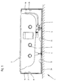
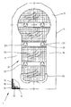
- the device 1 shown in Figures 1 and 2 is used to hold a Bathtub 2, with a whirlpool device 3, which is significant in operation Noise is caused, is equipped, and consists of a closed housing 11 surrounding bath 2, of which in particular sound waves caused by the whirl device 3 are absorbed, so that the bathtub 2 without nuisance for third parties Apartment buildings can be used.
- the housing 11 is here essentially from all around the bathtub 2 protruding base plate 12 attached to this vertically protruding Support struts 13, on the outside of which cover plates 16 are attached, and a ledge 17, which is held on the support struts 13. Moreover are the base plates 12, the cover plates 16 and possibly also the ledge 17 on the inside with an insulating, in particular sound-absorbing Edition 31 equipped.
- the support struts 13 are, as can be seen in particular in FIG. 3, as Profile pieces 14 - their profile is shown in dash-dotted lines in Figure 3 - formed and by means of plates 15 and welded thereto penetrating screws 27 attached to the base plate 2. At the top ends the support struts 13 are attached to these circumferential cross struts 18 with which the ledge 17 is connected by screws 28.
- the cross struts 18 exist here from a bracket 19 designed for the ledge 17 and a vertically projecting leg 20, which by means of screws 22 with the Support struts 13 is connected.
- elongated holes 21 are provided in the support struts 13 incorporated so that the cross struts 18 and thus the ledge 17 in height can be adjusted and thus aligned. They are on the outside Cover plates 16 and also the ledge 17 with a panel 25 in the form of Tiles or similar Mistake.
- the insulating pad 31 is inserted into individual frames 32 Insulating mats 33 formed, via the nets 34 to protect against damage are excited.
- the noises generated by the whirl device 3 are thus in cooperation with the air space between the pad 31 and the bathtub 2 damped, so that the bath 2, the bottom plate 12 by means of a elastic intermediate layer 26 is supported on the ground, by means of Device 1 can not only be placed freely in a room, but by these will not cause any unpleasant noises when bathing.
- the ledge 17 is stiffened in the corner areas by elbows 24 Device 1 accordingly has a high strength
Landscapes
- Health & Medical Sciences (AREA)
- Public Health (AREA)
- Epidemiology (AREA)
- General Health & Medical Sciences (AREA)
- Percussion Or Vibration Massage (AREA)
- Floor Finish (AREA)
- Mechanical Treatment Of Semiconductor (AREA)
Abstract
Description
- Figur 1
- die in der Vorrichtung eingebaute Badewanne, in Seitenansicht,
- Figur 2
- das Gehäuse der Vorrichtung nach Figur 1, in Draufsicht, und
- Figur 3
- einen Ausschnitt aus dem Gehäuse nach Figur 1, in einer vergrößerten Darstellung.
Claims (16)
- Vorrichtung (1) zur Halterung einer mit einer Whirl-Einrichtung (3) ausgestatteten Badewanne (2),
dadurch gekennzeichnet, dass die Badewanne (2) in einem diese vorzugsweise allseits umgebenden Gehäuse (11) eingesetzt ist, das aus einer seitlich über die Badewanne (2) überstehenden Bodenplatte (12), an dieser befestigten vertikal gerichteten und mit seitlichem Abstand zueinander angeordneten Stützstreben (13), an diesen unmittelbar oder über Zwischenglieder angebrachten Abdeckplatten (16) sowie einem an den Stützstreben (13) gehaltenen in Richtung der Badewanne (2) auskragenden Sims (17) zusammengesetzt ist, und dass die Bodenplatte (12), die Abdeckplatten (16) und/oder der Sims (16) auf den der Badewanne (2) zugekehrten Innenseiten ganz oder teilweise jeweils mit einer isolierenden, insbesondere Schallwellen absorbierenden Auflage (31) versehen sind. - Vorrichtung nach Patentanspruch,
dadurch gekennzeichnet, dass die Stützstreben (13) durch ein oder mehrfach abgekröpfte und/oder abkantbare an die Außenkontur der Bodenplatte (12) angepasste Profilstücke (14) gebildet sind, die mittels angeschweißter Stege (15) oder angeschraubter Winkelstücke an der Bodenplatte (12) befestigt sind. - Vorrichtung nach Anspruch 2,
dadurch gekennzeichnet, dass an den oberen Enden der Stützstreben (13) vorzugsweise rundum Querstreben (18) befestigt sind, die mit Auflager (19) für den Sims (17) versehen sind. - Vorrichtung nach Anspruch 3,
dadurch gekennzeichnet, dass die Querstreben (18) in der Höhe verstellbar mit den Stützstreben (13), z. B. mittels in diese eingearbeitete vertikal gerichtete Langlöcher (21) durchgreifender Schrauben (22), verbunden sind. - Vorrichtung nach Anspruch 3 oder 4,
dadurch gekennzeichnet, dass die Querstreben (18) aus einem Winkelstück (19) als Auflager für den Sims (17) und einem von dem Winkelstück (19) in Richtung der Stützstreben (13) abstehenden Schenkel (20) zur Verbindung mit diesen gebildet sind. - Vorrichtung nach Patentanspruch,
dadurch gekennzeichnet, dass die Bodenplatte (12) in Form eines Vieleckes ausgebildet ist und dass die Stützstreben (13) jeweils in einem Eckbereich der Bodenplatte (12) an dieser befestigt sind. - Vorrichtung nach Patentanspruch,
dadurch gekennzeichnet, dass die Bodenplatte (13) mit in Freisparungen der Auflage (31) angeordneten Stützplatten (23) zur Abstützung der Badewanne (2) über Zwischenglieder (4) versehen ist. - Vorrichtung nach Patentanspruch,
dadurch gekennzeichnet, dass die Badewanne (2) in dem Gehäuse (11) an dem Sims (17) aufgehängt ist. - Vorrichtung nach Patentanspruch,
dadurch gekennzeichnet, dass der Sims (17) die Badewanne (2) in deren Randbereich über- oder untergreift oder mit dem Rand der Badewanne (2) bündig angeordnet ist. - Vorrichtung nach Patentanspruch,
dadurch gekennzeichnet, dass der Sims (17) in den Eckbereichen durch im Querschnitt U-förmig ausgebildete Winkelstücke (24) versteift ist. - Vorrichtung nach Patentanspruch,
dadurch gekennzeichnet, dass die an der Bodenplatte (11), den Abdeckplbtten (16) und/oder dem Sims (17) angebrachte Auflage (31) durch in einzelnen Rahmen (32) eingesetzte Isolationsmatten (33) gebildet ist. - Vorrichtung nach Patentanspruch,
dadurch gekennzeichnet, dass die Isolationsmatten (33) auf der der Badewanne (2) zugekehrten Innenseite durch an den Rahmen (32) angebrachte Netze (24) abgedeckt sind. - Vorrichtung nach Patentanspruch,
dadurch gekennzeichnet, dass zumindest eine der Abdeckplatten (16) verschwenkbar oder abnehmbar mit den Stützstreben (13) verbunden ist. - Vorrichtung nach Patentanspruch,
dadurch gekennzeichnet, dass die Abdeckplatten (16) auf den Außenseiten mit einer Verkleidung (25), z. B. in Form von Fliesen oder dgl., versehen sind. - Vorrichtung nach Anspruch 1,
dadurch gekennzeichnet, dass die Bodenplatte (12) des Gehäuses (11) über eine elastische Zwischenlage (26) auf dem Untergrund abgestützt ist. - Vorrichtung nach Anspruch 1,
dadurch gekennzeichnet, dass bei einer einseitig an einer Wand angeordneten Badewanne (2) zwischen dieser und Wand eine Isolationsschicht vorgesehen ist.
Applications Claiming Priority (2)
| Application Number | Priority Date | Filing Date | Title |
|---|---|---|---|
| CH14552000 | 2000-07-25 | ||
| CH14552000 | 2000-07-25 |
Publications (2)
| Publication Number | Publication Date |
|---|---|
| EP1175861A1 true EP1175861A1 (de) | 2002-01-30 |
| EP1175861B1 EP1175861B1 (de) | 2005-08-03 |
Family
ID=4565491
Family Applications (1)
| Application Number | Title | Priority Date | Filing Date |
|---|---|---|---|
| EP01810727A Expired - Lifetime EP1175861B1 (de) | 2000-07-25 | 2001-07-20 | Badewannen-Haltevorrichtung |
Country Status (3)
| Country | Link |
|---|---|
| EP (1) | EP1175861B1 (de) |
| AT (1) | ATE300908T1 (de) |
| DE (2) | DE20105503U1 (de) |
Families Citing this family (3)
| Publication number | Priority date | Publication date | Assignee | Title |
|---|---|---|---|---|
| EP1844689A3 (de) * | 2006-04-10 | 2013-12-18 | Alfred Gassmann | Wanneneinbausystem für eine mit einer Whirl-einrichtung ausgestattete badewanne |
| EP2014206A1 (de) * | 2007-07-13 | 2009-01-14 | Urs Gassmann | Vorrichtung zur Halterung einer mit einer Whirl-Einrichtung ausgestatteten Badewanne |
| CH708098A2 (de) | 2013-05-15 | 2014-11-28 | Paul Trottmann | Tragrahmen mit Steckverbindungen und Steckverbindung zur Bildung eines Tragrahmens. |
Citations (2)
| Publication number | Priority date | Publication date | Assignee | Title |
|---|---|---|---|---|
| EP0450347A1 (de) * | 1990-04-05 | 1991-10-09 | HOESCH Metall + Kunststoffwerk GmbH & Co. | Tragrahmen für Whirlpool-Wannen |
| EP0635232A2 (de) * | 1993-07-19 | 1995-01-25 | E. Missel GmbH & Co. | Trägersystem für eine Bade- oder Brausewanne |
-
2001
- 2001-03-29 DE DE20105503U patent/DE20105503U1/de not_active Expired - Lifetime
- 2001-07-20 DE DE50106948T patent/DE50106948D1/de not_active Expired - Lifetime
- 2001-07-20 EP EP01810727A patent/EP1175861B1/de not_active Expired - Lifetime
- 2001-07-20 AT AT01810727T patent/ATE300908T1/de not_active IP Right Cessation
Patent Citations (2)
| Publication number | Priority date | Publication date | Assignee | Title |
|---|---|---|---|---|
| EP0450347A1 (de) * | 1990-04-05 | 1991-10-09 | HOESCH Metall + Kunststoffwerk GmbH & Co. | Tragrahmen für Whirlpool-Wannen |
| EP0635232A2 (de) * | 1993-07-19 | 1995-01-25 | E. Missel GmbH & Co. | Trägersystem für eine Bade- oder Brausewanne |
Also Published As
| Publication number | Publication date |
|---|---|
| EP1175861B1 (de) | 2005-08-03 |
| ATE300908T1 (de) | 2005-08-15 |
| DE50106948D1 (de) | 2005-09-08 |
| DE20105503U1 (de) | 2001-06-13 |
Similar Documents
| Publication | Publication Date | Title |
|---|---|---|
| DE3528334C2 (de) | Haltevorrichtung für die Vorderwandmontage von Sanitärapparaten, Armaturen, Rohrteilen und Leitungen | |
| EP0870459A2 (de) | Trägersystem für Bade-, Dusch- oder Whirlwannen | |
| EP1175861A1 (de) | Badewannen-Haltevorrichtung | |
| DE4126383C2 (de) | Verfahren und Montageelement zur Montage von Bade- und Duschwannen | |
| EP2182140A1 (de) | Bausatz für eine Sanitärzelle und Sanitärzelle hergestellt aus einem solchen Bausatz | |
| EP0662546A2 (de) | Montageblock zur wandseitigen Anbringung von bau- und haustechnischen Einrichtung und/oder Anlagen | |
| DE1554247A1 (de) | Aus Vertikalstuetzen und einhaengbaren Konsolen bestehende Tragkonstruktion fuer Regale od.dgl. | |
| US2580536A (en) | Mounting for wall forms | |
| EP0596512B1 (de) | Schnellbau-Trennwandsystem | |
| EP0891459B1 (de) | Trennwandvorrichtung für ladenlokale | |
| EP2014206A1 (de) | Vorrichtung zur Halterung einer mit einer Whirl-Einrichtung ausgestatteten Badewanne | |
| DE7613198U1 (de) | Badezimmereinrichtung | |
| DE19901031A1 (de) | Vorgefertigte Sanitärzelle | |
| EP1029988B1 (de) | Tragvorrichtung für sanitäre Einrichtungen | |
| EP0723757A1 (de) | Trägersystem für Bade- oder Duschwannen | |
| DE202006018203U1 (de) | Stützkonsole für Fenster- und Türauflager im Dämmraum bei zweischaligen Außenwänden aus Mauerwerk oder Beton | |
| DE8003863U1 (de) | Montageschiene fuer kunststoffbadewannen | |
| DE202005016946U1 (de) | Befestigungssystem für Sanitärelemente und Spülkasten | |
| EP0520269B1 (de) | Installationsblock | |
| DE10135112B4 (de) | Konstruktionssystem zur Herstellung von Baugruppen, wie Wand-,Boden-oder Deckenkonstruktionen | |
| DE202016105011U1 (de) | Wandinstallationseinheit | |
| DE1609384A1 (de) | Trennwand | |
| EP1918466B1 (de) | Installationssystem für sanitäre Einrichtungen und Verfahren zum Montieren eines solchen Installationssystems | |
| DE2630120A1 (de) | Gebaeude, insbesondere fertighaus | |
| CH635499A5 (en) | Method for fixing furniture |
Legal Events
| Date | Code | Title | Description |
|---|---|---|---|
| PUAI | Public reference made under article 153(3) epc to a published international application that has entered the european phase |
Free format text: ORIGINAL CODE: 0009012 |
|
| AK | Designated contracting states |
Kind code of ref document: A1 Designated state(s): AT BE CH CY DE DK ES FI FR GB GR IE IT LI LU MC NL PT SE TR |
|
| AX | Request for extension of the european patent |
Free format text: AL;LT;LV;MK;RO;SI |
|
| 17P | Request for examination filed |
Effective date: 20020727 |
|
| AKX | Designation fees paid |
Free format text: AT BE CH CY DE DK ES FI FR GB GR IE IT LI LU MC NL PT SE TR |
|
| 17Q | First examination report despatched |
Effective date: 20030314 |
|
| GRAP | Despatch of communication of intention to grant a patent |
Free format text: ORIGINAL CODE: EPIDOSNIGR1 |
|
| GRAS | Grant fee paid |
Free format text: ORIGINAL CODE: EPIDOSNIGR3 |
|
| GRAA | (expected) grant |
Free format text: ORIGINAL CODE: 0009210 |
|
| AK | Designated contracting states |
Kind code of ref document: B1 Designated state(s): AT BE CH CY DE DK ES FI FR GB GR IE IT LI LU MC NL PT SE TR |
|
| PG25 | Lapsed in a contracting state [announced via postgrant information from national office to epo] |
Ref country code: FI Free format text: LAPSE BECAUSE OF FAILURE TO SUBMIT A TRANSLATION OF THE DESCRIPTION OR TO PAY THE FEE WITHIN THE PRESCRIBED TIME-LIMIT Effective date: 20050803 Ref country code: TR Free format text: LAPSE BECAUSE OF FAILURE TO SUBMIT A TRANSLATION OF THE DESCRIPTION OR TO PAY THE FEE WITHIN THE PRESCRIBED TIME-LIMIT Effective date: 20050803 Ref country code: NL Free format text: LAPSE BECAUSE OF FAILURE TO SUBMIT A TRANSLATION OF THE DESCRIPTION OR TO PAY THE FEE WITHIN THE PRESCRIBED TIME-LIMIT Effective date: 20050803 |
|
| REG | Reference to a national code |
Ref country code: GB Ref legal event code: FG4D Free format text: NOT ENGLISH |
|
| REG | Reference to a national code |
Ref country code: CH Ref legal event code: EP |
|
| REG | Reference to a national code |
Ref country code: IE Ref legal event code: FG4D Free format text: LANGUAGE OF EP DOCUMENT: GERMAN |
|
| REF | Corresponds to: |
Ref document number: 50106948 Country of ref document: DE Date of ref document: 20050908 Kind code of ref document: P |
|
| REG | Reference to a national code |
Ref country code: CH Ref legal event code: NV Representative=s name: OK PAT AG PATENTE MARKEN LIZENZEN |
|
| GBT | Gb: translation of ep patent filed (gb section 77(6)(a)/1977) |
Effective date: 20050921 |
|
| PG25 | Lapsed in a contracting state [announced via postgrant information from national office to epo] |
Ref country code: DK Free format text: LAPSE BECAUSE OF FAILURE TO SUBMIT A TRANSLATION OF THE DESCRIPTION OR TO PAY THE FEE WITHIN THE PRESCRIBED TIME-LIMIT Effective date: 20051103 Ref country code: SE Free format text: LAPSE BECAUSE OF FAILURE TO SUBMIT A TRANSLATION OF THE DESCRIPTION OR TO PAY THE FEE WITHIN THE PRESCRIBED TIME-LIMIT Effective date: 20051103 Ref country code: GR Free format text: LAPSE BECAUSE OF FAILURE TO SUBMIT A TRANSLATION OF THE DESCRIPTION OR TO PAY THE FEE WITHIN THE PRESCRIBED TIME-LIMIT Effective date: 20051103 |
|
| PG25 | Lapsed in a contracting state [announced via postgrant information from national office to epo] |
Ref country code: ES Free format text: LAPSE BECAUSE OF FAILURE TO SUBMIT A TRANSLATION OF THE DESCRIPTION OR TO PAY THE FEE WITHIN THE PRESCRIBED TIME-LIMIT Effective date: 20051114 |
|
| PG25 | Lapsed in a contracting state [announced via postgrant information from national office to epo] |
Ref country code: PT Free format text: LAPSE BECAUSE OF FAILURE TO SUBMIT A TRANSLATION OF THE DESCRIPTION OR TO PAY THE FEE WITHIN THE PRESCRIBED TIME-LIMIT Effective date: 20060103 |
|
| NLV1 | Nl: lapsed or annulled due to failure to fulfill the requirements of art. 29p and 29m of the patents act | ||
| ET | Fr: translation filed | ||
| PLBE | No opposition filed within time limit |
Free format text: ORIGINAL CODE: 0009261 |
|
| STAA | Information on the status of an ep patent application or granted ep patent |
Free format text: STATUS: NO OPPOSITION FILED WITHIN TIME LIMIT |
|
| 26N | No opposition filed |
Effective date: 20060504 |
|
| PG25 | Lapsed in a contracting state [announced via postgrant information from national office to epo] |
Ref country code: MC Free format text: LAPSE BECAUSE OF NON-PAYMENT OF DUE FEES Effective date: 20060731 |
|
| PGFP | Annual fee paid to national office [announced via postgrant information from national office to epo] |
Ref country code: LU Payment date: 20080723 Year of fee payment: 8 |
|
| PG25 | Lapsed in a contracting state [announced via postgrant information from national office to epo] |
Ref country code: CY Free format text: LAPSE BECAUSE OF FAILURE TO SUBMIT A TRANSLATION OF THE DESCRIPTION OR TO PAY THE FEE WITHIN THE PRESCRIBED TIME-LIMIT Effective date: 20050803 |
|
| PGFP | Annual fee paid to national office [announced via postgrant information from national office to epo] |
Ref country code: IE Payment date: 20080728 Year of fee payment: 8 |
|
| PGFP | Annual fee paid to national office [announced via postgrant information from national office to epo] |
Ref country code: GB Payment date: 20080722 Year of fee payment: 8 |
|
| PGFP | Annual fee paid to national office [announced via postgrant information from national office to epo] |
Ref country code: BE Payment date: 20080801 Year of fee payment: 8 |
|
| BERE | Be: lapsed |
Owner name: *GASSMANN ALFRED Effective date: 20090731 |
|
| GBPC | Gb: european patent ceased through non-payment of renewal fee |
Effective date: 20090720 |
|
| REG | Reference to a national code |
Ref country code: IE Ref legal event code: MM4A |
|
| PG25 | Lapsed in a contracting state [announced via postgrant information from national office to epo] |
Ref country code: GB Free format text: LAPSE BECAUSE OF NON-PAYMENT OF DUE FEES Effective date: 20090720 |
|
| REG | Reference to a national code |
Ref country code: CH Ref legal event code: NV Representative=s name: PATENTBUERO REB & PARTNER |
|
| PG25 | Lapsed in a contracting state [announced via postgrant information from national office to epo] |
Ref country code: BE Free format text: LAPSE BECAUSE OF NON-PAYMENT OF DUE FEES Effective date: 20090731 |
|
| PG25 | Lapsed in a contracting state [announced via postgrant information from national office to epo] |
Ref country code: IE Free format text: LAPSE BECAUSE OF NON-PAYMENT OF DUE FEES Effective date: 20090720 |
|
| PGFP | Annual fee paid to national office [announced via postgrant information from national office to epo] |
Ref country code: IT Payment date: 20100728 Year of fee payment: 10 Ref country code: AT Payment date: 20100727 Year of fee payment: 10 |
|
| REG | Reference to a national code |
Ref country code: CH Ref legal event code: PFA Owner name: GASSMANN, ALFRED Free format text: GASSMANN, ALFRED#MEIERSKAPPELSTRASSE 1#6044 UDLIGENSWIL (CH) -TRANSFER TO- GASSMANN, ALFRED#MEIERSKAPPELSTRASSE 1#6044 UDLIGENSWIL (CH) |
|
| PG25 | Lapsed in a contracting state [announced via postgrant information from national office to epo] |
Ref country code: LU Free format text: LAPSE BECAUSE OF NON-PAYMENT OF DUE FEES Effective date: 20090720 |
|
| REG | Reference to a national code |
Ref country code: AT Ref legal event code: MM01 Ref document number: 300908 Country of ref document: AT Kind code of ref document: T Effective date: 20110720 |
|
| PG25 | Lapsed in a contracting state [announced via postgrant information from national office to epo] |
Ref country code: IT Free format text: LAPSE BECAUSE OF NON-PAYMENT OF DUE FEES Effective date: 20110720 |
|
| PGFP | Annual fee paid to national office [announced via postgrant information from national office to epo] |
Ref country code: FR Payment date: 20120803 Year of fee payment: 12 |
|
| PG25 | Lapsed in a contracting state [announced via postgrant information from national office to epo] |
Ref country code: AT Free format text: LAPSE BECAUSE OF NON-PAYMENT OF DUE FEES Effective date: 20110720 |
|
| PGFP | Annual fee paid to national office [announced via postgrant information from national office to epo] |
Ref country code: DE Payment date: 20130730 Year of fee payment: 13 |
|
| PGFP | Annual fee paid to national office [announced via postgrant information from national office to epo] |
Ref country code: CH Payment date: 20131031 Year of fee payment: 13 |
|
| REG | Reference to a national code |
Ref country code: CH Ref legal event code: PFA Owner name: GASSMANN, ALFRED, CH Free format text: FORMER OWNER: GASSMANN, ALFRED, CH |
|
| REG | Reference to a national code |
Ref country code: FR Ref legal event code: ST Effective date: 20140331 |
|
| PG25 | Lapsed in a contracting state [announced via postgrant information from national office to epo] |
Ref country code: FR Free format text: LAPSE BECAUSE OF NON-PAYMENT OF DUE FEES Effective date: 20130731 |
|
| REG | Reference to a national code |
Ref country code: DE Ref legal event code: R119 Ref document number: 50106948 Country of ref document: DE |
|
| REG | Reference to a national code |
Ref country code: CH Ref legal event code: PL |
|
| PG25 | Lapsed in a contracting state [announced via postgrant information from national office to epo] |
Ref country code: DE Free format text: LAPSE BECAUSE OF NON-PAYMENT OF DUE FEES Effective date: 20150203 Ref country code: CH Free format text: LAPSE BECAUSE OF NON-PAYMENT OF DUE FEES Effective date: 20140731 Ref country code: LI Free format text: LAPSE BECAUSE OF NON-PAYMENT OF DUE FEES Effective date: 20140731 |
|
| REG | Reference to a national code |
Ref country code: DE Ref legal event code: R119 Ref document number: 50106948 Country of ref document: DE Effective date: 20150203 |