EP1173883B1 - Behandlungsvorrichtung für silizium-scheiben - Google Patents
Behandlungsvorrichtung für silizium-scheiben Download PDFInfo
- Publication number
- EP1173883B1 EP1173883B1 EP00936696A EP00936696A EP1173883B1 EP 1173883 B1 EP1173883 B1 EP 1173883B1 EP 00936696 A EP00936696 A EP 00936696A EP 00936696 A EP00936696 A EP 00936696A EP 1173883 B1 EP1173883 B1 EP 1173883B1
- Authority
- EP
- European Patent Office
- Prior art keywords
- bearing
- bearing member
- shaft
- container
- rotation
- Prior art date
- Legal status (The legal status is an assumption and is not a legal conclusion. Google has not performed a legal analysis and makes no representation as to the accuracy of the status listed.)
- Expired - Lifetime
Links
- XUIMIQQOPSSXEZ-UHFFFAOYSA-N Silicon Chemical compound [Si] XUIMIQQOPSSXEZ-UHFFFAOYSA-N 0.000 title claims abstract description 44
- 229910052710 silicon Inorganic materials 0.000 title claims abstract description 44
- 239000010703 silicon Substances 0.000 title claims abstract description 44
- 235000012431 wafers Nutrition 0.000 title claims abstract description 34
- 230000005291 magnetic effect Effects 0.000 claims abstract description 24
- 239000000463 material Substances 0.000 claims abstract description 22
- 239000012530 fluid Substances 0.000 claims abstract 5
- 230000004308 accommodation Effects 0.000 claims abstract 3
- 230000008901 benefit Effects 0.000 claims description 9
- 239000011248 coating agent Substances 0.000 claims description 3
- 238000000576 coating method Methods 0.000 claims description 3
- 238000000034 method Methods 0.000 description 19
- 230000008569 process Effects 0.000 description 12
- 238000001816 cooling Methods 0.000 description 9
- 239000000126 substance Substances 0.000 description 9
- 238000004140 cleaning Methods 0.000 description 8
- 239000007789 gas Substances 0.000 description 8
- 239000007788 liquid Substances 0.000 description 7
- 238000004519 manufacturing process Methods 0.000 description 7
- 229910052757 nitrogen Inorganic materials 0.000 description 7
- 238000003860 storage Methods 0.000 description 7
- 239000002887 superconductor Substances 0.000 description 7
- 238000005530 etching Methods 0.000 description 6
- 229910052717 sulfur Inorganic materials 0.000 description 6
- 238000005516 engineering process Methods 0.000 description 5
- 230000004907 flux Effects 0.000 description 5
- 239000011253 protective coating Substances 0.000 description 5
- 239000004065 semiconductor Substances 0.000 description 5
- 230000007704 transition Effects 0.000 description 5
- 238000005299 abrasion Methods 0.000 description 4
- 239000013078 crystal Substances 0.000 description 4
- 238000001035 drying Methods 0.000 description 4
- 239000002245 particle Substances 0.000 description 4
- 238000013016 damping Methods 0.000 description 3
- 230000007547 defect Effects 0.000 description 3
- 230000006870 function Effects 0.000 description 3
- 229920002120 photoresistant polymer Polymers 0.000 description 3
- 239000004033 plastic Substances 0.000 description 3
- 229920003023 plastic Polymers 0.000 description 3
- 229920001343 polytetrafluoroethylene Polymers 0.000 description 3
- 239000004810 polytetrafluoroethylene Substances 0.000 description 3
- 229920002981 polyvinylidene fluoride Polymers 0.000 description 3
- IJGRMHOSHXDMSA-UHFFFAOYSA-N Atomic nitrogen Chemical compound N#N IJGRMHOSHXDMSA-UHFFFAOYSA-N 0.000 description 2
- XEEYBQQBJWHFJM-UHFFFAOYSA-N Iron Chemical compound [Fe] XEEYBQQBJWHFJM-UHFFFAOYSA-N 0.000 description 2
- 239000002033 PVDF binder Substances 0.000 description 2
- 238000010521 absorption reaction Methods 0.000 description 2
- OKTJSMMVPCPJKN-UHFFFAOYSA-N activated carbon Substances [C] OKTJSMMVPCPJKN-UHFFFAOYSA-N 0.000 description 2
- 239000010949 copper Substances 0.000 description 2
- 230000003993 interaction Effects 0.000 description 2
- 238000002955 isolation Methods 0.000 description 2
- 238000011068 loading method Methods 0.000 description 2
- 230000005415 magnetization Effects 0.000 description 2
- 238000012423 maintenance Methods 0.000 description 2
- 230000007246 mechanism Effects 0.000 description 2
- 230000035699 permeability Effects 0.000 description 2
- 238000012545 processing Methods 0.000 description 2
- 238000003908 quality control method Methods 0.000 description 2
- 230000001360 synchronised effect Effects 0.000 description 2
- 238000007704 wet chemistry method Methods 0.000 description 2
- 241000954177 Bangana ariza Species 0.000 description 1
- RYGMFSIKBFXOCR-UHFFFAOYSA-N Copper Chemical compound [Cu] RYGMFSIKBFXOCR-UHFFFAOYSA-N 0.000 description 1
- 229910052779 Neodymium Inorganic materials 0.000 description 1
- 229910052772 Samarium Inorganic materials 0.000 description 1
- 241000555745 Sciuridae Species 0.000 description 1
- 239000002253 acid Substances 0.000 description 1
- 230000033228 biological regulation Effects 0.000 description 1
- 230000015572 biosynthetic process Effects 0.000 description 1
- 230000009172 bursting Effects 0.000 description 1
- 239000004918 carbon fiber reinforced polymer Substances 0.000 description 1
- 239000004020 conductor Substances 0.000 description 1
- 239000000356 contaminant Substances 0.000 description 1
- 238000011109 contamination Methods 0.000 description 1
- 229910052802 copper Inorganic materials 0.000 description 1
- 238000005260 corrosion Methods 0.000 description 1
- 230000007797 corrosion Effects 0.000 description 1
- 230000002950 deficient Effects 0.000 description 1
- 239000008367 deionised water Substances 0.000 description 1
- 229910021641 deionized water Inorganic materials 0.000 description 1
- 230000001419 dependent effect Effects 0.000 description 1
- 238000013461 design Methods 0.000 description 1
- 239000003599 detergent Substances 0.000 description 1
- 238000011161 development Methods 0.000 description 1
- 230000005292 diamagnetic effect Effects 0.000 description 1
- 238000007598 dipping method Methods 0.000 description 1
- 230000000694 effects Effects 0.000 description 1
- 230000005284 excitation Effects 0.000 description 1
- 239000011152 fibreglass Substances 0.000 description 1
- 238000007667 floating Methods 0.000 description 1
- 238000011010 flushing procedure Methods 0.000 description 1
- 238000007710 freezing Methods 0.000 description 1
- 230000008014 freezing Effects 0.000 description 1
- 238000007654 immersion Methods 0.000 description 1
- 230000006872 improvement Effects 0.000 description 1
- 230000006698 induction Effects 0.000 description 1
- 229910052742 iron Inorganic materials 0.000 description 1
- 238000001459 lithography Methods 0.000 description 1
- 239000000203 mixture Substances 0.000 description 1
- 229910001172 neodymium magnet Inorganic materials 0.000 description 1
- 230000010355 oscillation Effects 0.000 description 1
- 239000003973 paint Substances 0.000 description 1
- 230000010363 phase shift Effects 0.000 description 1
- -1 polytetrafluoroethylene Polymers 0.000 description 1
- 230000002265 prevention Effects 0.000 description 1
- 230000001681 protective effect Effects 0.000 description 1
- 238000000746 purification Methods 0.000 description 1
- 239000002994 raw material Substances 0.000 description 1
- 230000009467 reduction Effects 0.000 description 1
- 230000005417 remagnetization Effects 0.000 description 1
- 230000008439 repair process Effects 0.000 description 1
- 229910000938 samarium–cobalt magnet Inorganic materials 0.000 description 1
- 239000007787 solid Substances 0.000 description 1
- 239000007921 spray Substances 0.000 description 1
- 238000005507 spraying Methods 0.000 description 1
- 238000012546 transfer Methods 0.000 description 1
- 238000002604 ultrasonography Methods 0.000 description 1
- XLYOFNOQVPJJNP-UHFFFAOYSA-N water Chemical compound O XLYOFNOQVPJJNP-UHFFFAOYSA-N 0.000 description 1
- 238000003631 wet chemical etching Methods 0.000 description 1
- 238000004804 winding Methods 0.000 description 1
- 229910052727 yttrium Inorganic materials 0.000 description 1
Images


Classifications
-
- F—MECHANICAL ENGINEERING; LIGHTING; HEATING; WEAPONS; BLASTING
- F16—ENGINEERING ELEMENTS AND UNITS; GENERAL MEASURES FOR PRODUCING AND MAINTAINING EFFECTIVE FUNCTIONING OF MACHINES OR INSTALLATIONS; THERMAL INSULATION IN GENERAL
- F16C—SHAFTS; FLEXIBLE SHAFTS; ELEMENTS OR CRANKSHAFT MECHANISMS; ROTARY BODIES OTHER THAN GEARING ELEMENTS; BEARINGS
- F16C32/00—Bearings not otherwise provided for
- F16C32/04—Bearings not otherwise provided for using magnetic or electric supporting means
- F16C32/0406—Magnetic bearings
- F16C32/044—Active magnetic bearings
-
- F—MECHANICAL ENGINEERING; LIGHTING; HEATING; WEAPONS; BLASTING
- F16—ENGINEERING ELEMENTS AND UNITS; GENERAL MEASURES FOR PRODUCING AND MAINTAINING EFFECTIVE FUNCTIONING OF MACHINES OR INSTALLATIONS; THERMAL INSULATION IN GENERAL
- F16C—SHAFTS; FLEXIBLE SHAFTS; ELEMENTS OR CRANKSHAFT MECHANISMS; ROTARY BODIES OTHER THAN GEARING ELEMENTS; BEARINGS
- F16C32/00—Bearings not otherwise provided for
- F16C32/04—Bearings not otherwise provided for using magnetic or electric supporting means
- F16C32/0406—Magnetic bearings
- F16C32/0408—Passive magnetic bearings
- F16C32/0436—Passive magnetic bearings with a conductor on one part movable with respect to a magnetic field, e.g. a body of copper on one part and a permanent magnet on the other part
- F16C32/0438—Passive magnetic bearings with a conductor on one part movable with respect to a magnetic field, e.g. a body of copper on one part and a permanent magnet on the other part with a superconducting body, e.g. a body made of high temperature superconducting material such as YBaCuO
-
- F—MECHANICAL ENGINEERING; LIGHTING; HEATING; WEAPONS; BLASTING
- F16—ENGINEERING ELEMENTS AND UNITS; GENERAL MEASURES FOR PRODUCING AND MAINTAINING EFFECTIVE FUNCTIONING OF MACHINES OR INSTALLATIONS; THERMAL INSULATION IN GENERAL
- F16C—SHAFTS; FLEXIBLE SHAFTS; ELEMENTS OR CRANKSHAFT MECHANISMS; ROTARY BODIES OTHER THAN GEARING ELEMENTS; BEARINGS
- F16C37/00—Cooling of bearings
- F16C37/005—Cooling of bearings of magnetic bearings
-
- F—MECHANICAL ENGINEERING; LIGHTING; HEATING; WEAPONS; BLASTING
- F16—ENGINEERING ELEMENTS AND UNITS; GENERAL MEASURES FOR PRODUCING AND MAINTAINING EFFECTIVE FUNCTIONING OF MACHINES OR INSTALLATIONS; THERMAL INSULATION IN GENERAL
- F16C—SHAFTS; FLEXIBLE SHAFTS; ELEMENTS OR CRANKSHAFT MECHANISMS; ROTARY BODIES OTHER THAN GEARING ELEMENTS; BEARINGS
- F16C2300/00—Application independent of particular apparatuses
- F16C2300/30—Application independent of particular apparatuses related to direction with respect to gravity
- F16C2300/32—Horizontal, e.g. bearings for supporting a horizontal shaft
Definitions
- the invention relates to a device for treating objects, in particular of silicon wafers according to the claim 1.
- EP 0 570 967 A1 discloses an apparatus for treating silicon wafers known. These are subjected to several vacuum process steps. The wafers are stored in a vacuum container containing a Transport under vacuum conditions permits. At the bottom of the container A vacuum valve is provided by an electromagnet is operable. Not known from this, as silicon wafers at the same time highest purity in a medium can be treated.
- wet chemical Etching Due to the interaction processes with the silicon surfaces one differentiates two classes in the wafer treatment: the wet chemical Etching and wet chemical cleaning. Both processes are both in the disc production as raw material, as in the further treatment applied by the chip manufacturer.
- PTFE polytetrafluoroethylene
- PVDF polyvinylidene fluorides
- the wafers in packages become several slices vertically immersed in the baths with the chemicals or detergents.
- Highly specific ultrasound technologies are used to control over Cavitation mechanisms during the formation and bursting of gas bubbles the effectiveness of liquid purification, especially in the fine microstructures from 0.18 to 0.25 to further improve.
- a desire for the previous technologies is the rotation of the silicon wafers, but so far practiced only in the particle-critical processes (spin etching, spin drying).
- the technical design is here designed so that the silicon wafers are inserted into a plastic basket, a so-called wafer carrier.
- a gear or a drive roller is mounted axially.
- a drive unit engages the gear and rotates the basket in the bathroom. The speeds are kept small at 1 - 60 min -1 .
- the basket can also be replaced by a cage, with the silicon discs be held in three or four slotted bars.
- the bars can be rotated by a gearbox individually or as a group and Take the discs with you during the rotation.
- the advantage of the rod holder is the low shading of the discs.
- the invention is based on the object, a device for treatment of objects to provide a uniform treatment ensures the objects while maintaining the highest purity is.
- the object is achieved by the features of the characterizing part of the claim 1 solved.
- the essence of the invention is a rotatably driven Carrier device contactless in superconducting magnetic bearings too to store.
- the advantages thereby achieved are numerous.
- the storage position is self-stabilizing.
- the friction losses, especially at high speeds are very low.
- Except for the cooling of the superconductor is not a control system the bearings required, thereby increasing the reliability.
- the shaft and the fixed bearing parts can be vacuum-tight from each other be sealed, whereby an intrusion of the optionally highly aggressive Medium is avoided in the fixed bearing part. Warehousing has special properties in damping unwanted Vibrations that do not require their own regulation.
- the advantage of the device according to claim 3 is that the Shaft simply lifted from the stationary, second bearing part and replaced can be.
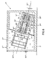
- a device 1 is the Wet chemical and gaseous treatment of objects, in particular of silicon wafers 2, also referred to as wafers, with a medium 3.
- the device 1 has one with the medium third filled or to be filled container 4, in which a carrier device 5 is rotatably arranged to receive the silicon wafers 2.
- the carrier device 5 is arranged in two at the end faces 6, 7 of the container 4 Bearing blocks 8, 9 stored. These are at the opposite Side of the carrier device 5 concentric with a substantially horizontally extending axis of rotation 10, a shaft stub 11 and a shaft drive stub 12 is provided, which together form a shaft.
- the shaft stump 11 and the shaft drive stump 12 are in the Bearing blocks 8 and 9 provided bearings 13 and 14 magnetically mounted.
- In the bearing block 9 is also a drive unit 15 for rotary drive the wave provided.
- the container 4 corresponds to those for the treatment of silicon wafers 2 known containers and is made of a highly corrosion-resistant plastic manufactured.
- the containers 4 may be in the form of a tank for liquid treatment or a chamber designed for gas or spray treatment his.
- the container 4 is on its inside with a Container coating 16 of an acid-resistant and chemically possible inert material, in particular PTFE or PVDF provided.
- PTFE PTFE
- PVDF a container coating 16 of an acid-resistant and chemically possible inert material
- the carrier device 5 has in each case frontally concentric to the axis of rotation 10 arranged, parallel to each other carrier discs 17, 18, which along its circumference over parallel to the axis of rotation 10 extending Carrier bars 19 are connected.
- the support bars 19 have slots 20 on, in which the silicon wafers 2 engage and thus be held.
- At least three carrier bars 19 are provided. It can, however In addition, additional support rods 19 may be provided.
- the carrier device 5 with silicon disks 2 may be one or more Carrier bars 19 are removed.
- the fixed in the carrier device 5 Silicon disks 2 are concentric with the axis of rotation 10 and parallel to each other arranged. As a result, upon rotation of the carrier device 5 around the axis of rotation 10 in the medium 3 ensures that the surfaces of the silicon wafers 2 as evenly as possible the medium 3 are suspended and so no inhomogeneities or defects arise.
- Carrier facilities There may be other known, inter alia, described above Carrier facilities are used.
- the bearing blocks 8, 9 are supported against a machine floor 21.
- the first bearing parts 22 are partially, in particular 50%, surrounding, by a bearing gap 23 separate second bearing parts 24 provided.
- the bearing gap 23 typically has a width from 0.5 to 10 mm.
- the first bearing part 22 has the shaft drive stump 12 concentrically surrounding, connected thereto, arranged adjacent to the axis of rotation 10, permanent ring magnets 25, wherein each adjacent ring magnets 25 arranged either an attractive (opposite magnetic polarity) or a repulsive force (same poles) or a combination, so that along the rotation axis 10, for example, a sequence S, N; N, S; S, N; N, S; ..., where N stands for the magnetic north pole and S for the south magnetic pole.
- the ring magnets 25 are made of SmCo, Sm 2 CO 17 or NdFeB. The latter achieves the highest energy densities and a remanence value of 1.4 Tesla.
- annular discs 26 are provided with high permeability, so that the magnetic flux in the bearing gap 23 is substantially perpendicular to the axis of rotation 10.
- the annular discs 26 typically have a thickness of 1 to 2 mm.
- the first bearing part 22 is provided to protect against the located in the bearing gap 23 medium 3 with a protective coating 27 which is made of the same material as the container coating 16.
- the ring magnets 25, the annular discs 26 and the Blunt 11, 12 thus come with the medium 3 is not in contact.
- the second bearing parts 24 each have an upwardly open bearing half-shell 28, which is made of a superconducting material and is parallel to the axis of rotation 10 and which is surrounded by a cooling jacket 28a, which is connected to a cooling jacket 28a for maintaining the superconducting state.
- Device 29 is connected via a heat-discharge line 30.
- the production of melt-textured high-temperature superconductors is in Werfel, Flögel - Delor, Wippich, "YBaCuO Large Scale Melt Texturing in a Temperature Gradiant", Inst.
- the critical current density is greater than 30 kA / cm 2 .
- the grain sizes and grain boundaries produce special hysteresis and damping properties in the material.
- the high temperature superconductor materials have crystals with a radially similar texture and a critical temperature of up to 92 Kelvin (i.e., 181 ° C), so that the superconductor materials can also be maintained below liquid transition temperature by liquid nitrogen. Other superconducting materials may be used.
- the cooling device 29 has a closed cryostat, which operates on the Stirling principle. It is also possible to provide chillers operating on the Gifford-McMahon or Pulse Tube method.
- the heat-removal line 30 and the cooling jacket 28a are made of a very good heat-conducting material, in particular copper.
- the bearing half-shell 28, the cooling jacket 28a and the heat-dissipating conduit 30 are surrounded by an intermediate space 31 separated from an intermediate housing 32 embedded in the bearing blocks 8 and 9, respectively. To increase the isolation of the bearing half-shell 28 from the environment of the intermediate space 31 is evacuated. The residual gas pressure in the intermediate space 31 is less than 10 -2 Pascal.
- activated carbon cells 33 are provided which increase the quality of the vacuum by the absorption of gas molecules on cooling.
- the second bearing part 24 and in particular the bearing half-shell 28 have a U-shaped cross section with a recess 34 which receives the first bearing part 22.
- the intermediate housing 32 At least in the area of the recess 34, the intermediate housing 32 on a protective coating 35 which consists of the same material as the protective coating 27.
- the intermediate housing 32 is provided in this area with a support layer 37 which consists of a glass fiber reinforced or carbon fiber reinforced plastic.
- the adjacent to the bearing 14 arranged drive unit 15 has a arranged in a stator block 38 stator 39 and one with the Shaft drive stump 12 integrally formed rotor 40 on.
- the stator 39 has a circular sector-shaped in cross-section upwardly open Coil core 41 with radially to the axis of rotation 10 inwardly projecting Coil pins 42 formed integrally with the coil core 41 on.
- the spool pins 42 are of drive coils 43 with terminals 44 wrapped so that the magnetic fields generated by the drive coils 43 extend substantially radially to the axis of rotation 10.
- the connections 44 are in a known manner with a power supply / control device connected.
- the rotor 40 has a stump 12 concentric surrounding rotor mantle 45, into the permanent bar magnets 46 are inserted with alternating polarity, so that along the circumference a polarity sequence N, S, N, S,.
- the by the permanent rod magnets 46 generated magnetic fields extend substantially radially to Rotary axis 10.
- the material for the rod magnets 46 may be the same material as are selected for the ring magnet 25.
- the rotor 40 may have a Wear squirrel cage.
- the electrical control of the adjacent ones Drive coils 43 takes place in a time sequence in such a way that the magnetic field generated by a drive coil 43, the rotor 40 in a Turn direction 47 repels and at the same time that in the direction of rotation 47 downstream drive coil 43 generated magnetic field Rotor 40 attracts.
- the unit of support means 5 as well as shaft stub 11 and shaft drive stub 12 are held by a robot arm (not shown) outside of the container 4 and the second bearing parts 24.
- the unit of support means 5 and shaft stub 11 and shaft drive stump 12 is lifted by the robot arm in the position shown in Fig. 2 and mechanically held in a so-called freezing position.
- the bearing shells 28 are cooled to a temperature below the transition temperature of the superconducting material. Thereafter, the carrier device 5 is released by the robot arm and "floats" separated by a bearing gap 23 in the second bearing parts 24. This is the result of a diamagnetic interaction that under the influence of an external magnetic field in the superconducting bearing.
- Half shell 28 are fired characteristic currents that produce a precisely opposite magnetic flux. Since the thrown currents flow essentially without resistance continuously and in turn generate an opposing magnetic field which repels the magnetic field of the ring magnets 25, the system operates essentially without power. In this way, the first bearing part 22 and the second bearing part 24 repel each other. Changes in position generate restoring magnetic forces.
- the shaft is mounted with a stiffness both axially and radially with respect to the axis of rotation 10.
- the bearings 13, 14 have an axial and radial bearing stiffness of more than 80 N / mm, in particular of more than 200 N / mm. Shifts in the axial or radial direction generate by the fixation of the magnetic flux in the superconductor, the so-called pinning effect, counter forces with the tendency to return the first bearing member 22 in the initial position, which is referred to as a key-lock principle. This explains the high bearing rigidity and automatic centering of the first bearing part 22 relative to the second bearing part 24.
- the bearings 13, 14 damp vibrations of the shaft in a frequency range of 0.1 Hz to 1 kHz.
- the storage allows speeds of up to 10000 min -1 .
- the weight of the stored unit can be 20 kg and more. Due to the non-contact storage, the bearings 13, 14 are not subject to wear.
- the bearings 13, 14 have an intrinsic damping characteristic, since small changes in the magnetic flux approximately in the radial magnetization of the ring magnets 25 in the superconducting material generate eddy currents and movements of the vortex grid. The resulting energies are released in the superconductor and thus damp oscillations of the wave.
- the bearings 13, 14 function passively, ie without electronic control, and are therefore fail-safe and maintenance-free.
- the cooling device 29 of the bearing half-shells 28 is briefly deactivated after this unit has been detected by a robot arm.
- the temperature of the bearing half-shells 28 rises to near the transition temperature. This is accompanied by a reduction of the magnetic forces, without affecting the floating state of the unit, which can now be easily lifted out of the second bearing parts 24 to remove the machined silicon wafers 2.
- the particular practical value lies in the simple removal and reinstatement of the support means 5 in the bearing parts 24. This requires no switching or control functions in the storage area.
- a second embodiment of the invention differs from the first embodiment only by the structure of the drive unit 15 '.
- end of Shaft drive stump 12 ' is a perpendicular to the axis of rotation 10 extending Hysteresis disc 48 made of a material with a pronounced hysteresis curve intended.
- Adjacent to this is a via a support 49th supported against the machine base 21, concentric with the axis of rotation 10 extending, designed as a coil ring 50 coil unit with Three-phase winding provided.
- the coil ring 50 has a ring core 51 on, which at different, evenly over the ring core 51 distributed positions with drive coils 43 'is wrapped.
- a Protective cover 52 provided, which is made of the same material, like the protective coating 27. The same applies to the stump 12 'and the disc 48. The operation of such a drive is known. At the Remagnetization of hysteretic iron occurs between exciting magnetic Field strength and magnetic induction a phase shift on.
- the hysteresis disc 48 is formed as a massive disc and can be cover well. It is also possible to use the hysteresis disc 48 as a tube train. During startup, the hysteresis drive behaves like an asynchronous motor; Once the rated speed has been reached, the result is synchronous operation. The advantage of this drive is mainly that no rod magnets 46 are needed and a synchronous drive can be built.
- FIG. 6 a third embodiment will be described of the invention. Identical parts are given the same reference numerals as in the first embodiment; different, however functionally equivalent parts are given the same reference numerals with two raised strokes. Otherwise, the description of the first Reference example.
- the central difference of the third embodiment compared to the first embodiment is that the Rotary axis 10 is not horizontal, but vertical.
- the second bearing part 24" is provided which, like the bearing part 24 of the first embodiment is constructed.
- a bearing disc 53 is provided of a superconducting material.
- the container 4 arranged in which the carrier device 5" with vertical extending axis of rotation 10 is arranged. Am in in Fig.
- the first bearing part 22" is provided, which concentric with each other, magnetized parallel to the axis of rotation 10 Ring magnets 25 ", there may be more than two concentric Ring magnets 25 “be provided.
- the magnetization respectively adjacent Ring magnets 25 “ is alternating between the ring magnets 25"
- annular disks 26 "with low permeability can be provided his.
- the bearing 13 " has both axial and radial bearing stiffness on.
- the support means 5 can be kept open at the top and allows a frontal loading with a separate carrier cage, e.g. from two half-shells.
- the half-shells have slotted, axial Rods in which the silicon discs 2 are inserted.
- the two half shells are pressed together, axially in the support means 5 'of pushed in at the top and fixed in axial guides.
- the bearings 13, 14 of the first embodiment and the bearing 13 "of the third Embodiment can of course be combined with each other. In this way, the bearing stiffness in radial and axial Direction are increased and the rotation axis is an angle between 0 and 90 ° to the horizontal, d. H. any position between a horizontal arrangement and a vertical arrangement, occupy.
- FIG. 7 a fourth embodiment will be described of the invention. Identical parts are given the same reference numerals as in the first embodiment, to the description thereof Reference is hereby made. Structurally different, but functional like parts are given the same reference numerals with three superscripts Strokes.
- the carrier device 5 "' has a parallel to the axis of rotation 10 "'from the outside retractable auxiliary carrier basket 60 on which the silicon discs 2 absorbs. The basket 60 may end in the carrier device 5 '"inserted or removed from this.
- the carrier device 5 "' is arranged concentrically to the axis of rotation 10"' and to the shaft drive stub 12 "'at the shaft drive stub 12 "'opposite end of the carrier device 5"' is
- the bearing part 22 "' is provided on the circumference, the bearing part 22"' points along the circumference adjacent to each other arranged permanent magnets 55 with radial orientation.
- the bearing block 8 '' provided with the bearing part 24 ''
- the bearing part 24 "' is circular segment-shaped and surrounds the bearing part 22"' partially.
- the container 4 "' has a connected via a hinge 56 to the bearing block 8 "'vertical Side wall 57 and one with the upper end of the bearing block 9 "'on a Hinge 58 connected side wall 59 on.
- the side walls 57 and 59 can be swiveled outwards.
- the silicon disks 2 charged Carrier device 5 "" in the container 5 “" about the axis of rotation 10 "” be rotated.
- the advantage of the embodiment is that the Silicon discs along the axis of rotation 10 "" can be removed.
- the unit may consist of carrier device 5 “” and shaft drive stub 12 "” also along the axis of rotation 10 "” to cleaning or Repair purposes are removed.
- a separate support like through the bearing 13 "'in the fourth embodiment is not required.
- a sixth embodiment of the invention Identical parts are given the same reference numerals as in the fifth embodiment shown in FIG. 8, to the description of which reference is hereby made. Constructively different, However, functionally similar parts receive the same reference numerals with five raised dashes.
- the structure of the bearing parts 24 "" and the Drive unit 15 “" corresponds to the structure according to the fifth embodiment. The same applies to the structure of the rotor 40 with the exception that of a resistant cylindrical shell 61 made of plastic is surrounded.
- the arrangement of the rotor 40 is selected such that the axis of rotation 10 "" 'vertically runs.
- the bearing block 9 "" ' has at its lower end a drain opening 62 on, with the annulus between the jacket 61 and the Bearing parts 24 “" or the drive unit 15 “” is connected.
- the support plate 18 "" 'connected to the rotor 40 essentially extends horizontally and serves with its top as a support for a silicon disk 2.
- the container 4 "" ' which is designed as a lid 63, is laterally and arranged above the silicon wafer 2. It goes without saying possible to operate the device 1 "" 'without the container 4 "”'.
- the Cover 63 is centrally located a feed line 64, which in the vom Cover 63 limited space has a nozzle 65. Laterally below the Silicon disk 2, the lid 63 has a lid edge 66 with a discharge line 67 on.
- the operation of the device 1 "" 'according to the sixth embodiment the operation of the device 1 "" 'according to the sixth embodiment.
- the carrier disc 18 "" ' is like in the fifth embodiment, friction-driven rotatably mounted.
- To the Applying photoresist to the silicon wafer 2 will produce a drop of photoresist applied centrally through the nozzle 5 to the rotating silicon wafer 2.
- the photoresist spreads quickly, thin and homogeneous on the surface of the silicon disk 2.
- Excess Paint is through the discharge line 67 and the drain opening 62nd dissipated.
- the device 1 "" ' can also be used for those in the preceding Embodiments described etching and cleaning processes be used.
- the silicon wafer 2 in the device 1 "" 'to be centrifuged dry.
- the device 1 '"" for checking the accuracy of the crystal and Surface structure of the silicon wafer 2 can be used.
- the silicon wafer. 2 very fast to very high speeds, as described above, to accelerate. Hairline cracks and other imperfections in the crystal structure
- the silicon wafer 2 grow at correspondingly high centrifugal forces and can be easily determined. If necessary, these defects lead even the breakage of the disc 2.
Landscapes
- Engineering & Computer Science (AREA)
- General Engineering & Computer Science (AREA)
- Mechanical Engineering (AREA)
- Cleaning Or Drying Semiconductors (AREA)
- Container, Conveyance, Adherence, Positioning, Of Wafer (AREA)
- Crystals, And After-Treatments Of Crystals (AREA)
- Magnetic Bearings And Hydrostatic Bearings (AREA)
- Chemically Coating (AREA)
- Silicon Compounds (AREA)
Applications Claiming Priority (5)
| Application Number | Priority Date | Filing Date | Title |
|---|---|---|---|
| DE19918922 | 1999-04-27 | ||
| DE19918922 | 1999-04-27 | ||
| DE19959299 | 1999-12-09 | ||
| DE19959299A DE19959299A1 (de) | 1999-04-27 | 1999-12-09 | Behandlungsvorrichtung für Silizium-Scheiben |
| PCT/EP2000/003351 WO2000065637A2 (de) | 1999-04-27 | 2000-04-13 | Behandlungsvorrichtung für silizium-scheiben |
Publications (2)
| Publication Number | Publication Date |
|---|---|
| EP1173883A2 EP1173883A2 (de) | 2002-01-23 |
| EP1173883B1 true EP1173883B1 (de) | 2003-10-01 |
Family
ID=26053088
Family Applications (1)
| Application Number | Title | Priority Date | Filing Date |
|---|---|---|---|
| EP00936696A Expired - Lifetime EP1173883B1 (de) | 1999-04-27 | 2000-04-13 | Behandlungsvorrichtung für silizium-scheiben |
Country Status (7)
| Country | Link |
|---|---|
| US (1) | US7048824B1 (enExample) |
| EP (1) | EP1173883B1 (enExample) |
| JP (1) | JP2004507068A (enExample) |
| CN (1) | CN1349655A (enExample) |
| AT (1) | ATE251340T1 (enExample) |
| AU (1) | AU5210300A (enExample) |
| WO (1) | WO2000065637A2 (enExample) |
Families Citing this family (12)
| Publication number | Priority date | Publication date | Assignee | Title |
|---|---|---|---|---|
| JP3808709B2 (ja) * | 2000-07-19 | 2006-08-16 | 大日本スクリーン製造株式会社 | 基板処理装置 |
| JP4026750B2 (ja) | 2002-04-24 | 2007-12-26 | 東京エレクトロン株式会社 | 基板処理装置 |
| JP4486649B2 (ja) * | 2004-10-28 | 2010-06-23 | 東京エレクトロン株式会社 | 液処理装置 |
| US8471254B2 (en) * | 2005-12-27 | 2013-06-25 | Hana Microdisplay Technologies, Inc. | Liquid crystal cells with uniform cell gap and methods of manufacture |
| CN101432622B (zh) * | 2006-03-03 | 2013-05-29 | 国立大学法人新澙大学 | 存在于硅晶片中的原子空位的定量评价装置和方法 |
| JP5276347B2 (ja) * | 2007-07-03 | 2013-08-28 | 国立大学法人 新潟大学 | シリコンウェーハ中に存在する原子空孔の定量評価装置、その方法、シリコンウェーハの製造方法、及び薄膜振動子 |
| CN101217108B (zh) * | 2008-01-02 | 2010-06-09 | 株洲南车时代电气股份有限公司 | 一种芯片台面腐蚀装置 |
| US20100038498A1 (en) * | 2008-08-18 | 2010-02-18 | Skedco, Inc. | Configurable anchor point and modular kit for an anchor point |
| US20120098371A1 (en) * | 2010-10-22 | 2012-04-26 | Spinlectrix Inc. | Stabilization of rotating machinery |
| JP5715444B2 (ja) * | 2011-02-28 | 2015-05-07 | 東京エレクトロン株式会社 | 載置装置 |
| DE102019135182A1 (de) * | 2019-12-19 | 2021-06-24 | Oerlikon Surface Solutions Ag, Pfäffikon | Haltevorrichtung zum Halten eines Substrats |
| DE102023131367A1 (de) * | 2023-11-10 | 2025-05-15 | Gebr. Schmid Gmbh | Vorrichtung, Verfahren und Anlage zur Leiterplattenherstellung |
Family Cites Families (20)
| Publication number | Priority date | Publication date | Assignee | Title |
|---|---|---|---|---|
| CH469404A (fr) * | 1968-01-26 | 1969-02-28 | Ebauches Sa | Diviseur de fréquence |
| US4300581A (en) * | 1980-03-06 | 1981-11-17 | Thompson Raymon F | Centrifugal wafer processor |
| EP0238908A1 (de) * | 1986-03-19 | 1987-09-30 | Siemens Aktiengesellschaft | Kryosorptionspumpe für ein thermisches Isoliervakuum im Läufer einer elektrischen Maschine mit supraleitender Erregerwicklung |
| DE3808331A1 (de) * | 1988-03-12 | 1989-09-28 | Kernforschungsanlage Juelich | Magnetische lagerung mit permanentmagneten zur aufnahme der radialen lagerkraefte |
| JPH0558777A (ja) * | 1991-08-27 | 1993-03-09 | Canon Inc | 薄膜形成装置 |
| JPH05238683A (ja) * | 1992-02-28 | 1993-09-17 | Ebara Corp | 磁気浮上エレベータ |
| US5398481A (en) * | 1992-05-19 | 1995-03-21 | Ebara Corporation | Vacuum processing system |
| JPH0758036A (ja) * | 1993-08-16 | 1995-03-03 | Ebara Corp | 薄膜形成装置 |
| JP3961032B2 (ja) * | 1993-12-13 | 2007-08-15 | シーメンス アクチエンゲゼルシヤフト | 回転子軸の磁気軸受装置 |
| WO1995020264A1 (en) * | 1994-01-25 | 1995-07-27 | Kanagawa Academy Of Science And Technology | Magnetic levitation device |
| JPH081475A (ja) * | 1994-06-22 | 1996-01-09 | Nippon Seiko Kk | ターンテーブル装置 |
| US5554583A (en) * | 1994-09-08 | 1996-09-10 | Hull; John R. | Permanent magnet design for high-speed superconducting bearings |
| DE19503695C2 (de) * | 1995-02-04 | 1997-02-27 | Roland Man Druckmasch | Absicherung für eine Druckmaschine |
| US5747426A (en) * | 1995-06-07 | 1998-05-05 | Commonwealth Research Corporation | High performance magnetic bearing systems using high temperature superconductors |
| TW331652B (en) * | 1995-06-16 | 1998-05-11 | Ebara Corp | Thin film vapor deposition apparatus |
| WO1997003225A1 (en) * | 1995-07-10 | 1997-01-30 | Cvc Products, Inc. | Programmable ultraclean electromagnetic substrate rotation apparatus and method for microelectronics manufacturing equipment |
| JP3672416B2 (ja) * | 1997-06-27 | 2005-07-20 | 株式会社荏原製作所 | スピン処理装置 |
| JP3847935B2 (ja) * | 1998-01-09 | 2006-11-22 | キヤノン株式会社 | 多孔質領域の除去方法及び半導体基体の製造方法 |
| DE19847347C2 (de) * | 1998-10-14 | 2001-03-29 | Ldt Gmbh & Co | Magnetlager |
| TW466576B (en) * | 1999-06-15 | 2001-12-01 | Ebara Corp | Substrate processing apparatus |
-
2000
- 2000-04-13 WO PCT/EP2000/003351 patent/WO2000065637A2/de not_active Ceased
- 2000-04-13 JP JP2000614487A patent/JP2004507068A/ja active Pending
- 2000-04-13 AU AU52103/00A patent/AU5210300A/en not_active Abandoned
- 2000-04-13 CN CN00806788A patent/CN1349655A/zh active Pending
- 2000-04-13 US US09/959,495 patent/US7048824B1/en not_active Expired - Fee Related
- 2000-04-13 EP EP00936696A patent/EP1173883B1/de not_active Expired - Lifetime
- 2000-04-13 AT AT00936696T patent/ATE251340T1/de not_active IP Right Cessation
Also Published As
| Publication number | Publication date |
|---|---|
| ATE251340T1 (de) | 2003-10-15 |
| AU5210300A (en) | 2000-11-10 |
| EP1173883A2 (de) | 2002-01-23 |
| CN1349655A (zh) | 2002-05-15 |
| WO2000065637A2 (de) | 2000-11-02 |
| WO2000065637A3 (de) | 2001-04-12 |
| US7048824B1 (en) | 2006-05-23 |
| JP2004507068A (ja) | 2004-03-04 |
Similar Documents
| Publication | Publication Date | Title |
|---|---|---|
| EP1173883B1 (de) | Behandlungsvorrichtung für silizium-scheiben | |
| DE69525861T2 (de) | Vorrichtung zum Speichern und Umwandeln von Energie | |
| EP1313959B1 (de) | Magnetlager zur lagerung einer drehbaren welle unter verwendung von hoch-tc-supraleitermaterial | |
| DE69126210T2 (de) | Supraleitende magnetlager für hohe temperaturen | |
| DE69231479T2 (de) | Magnetron-Plasma-Bearbeitungsvorrichtung | |
| DE69208558T2 (de) | Lagervorrichtung | |
| DE69225318T2 (de) | Magnetsupraleitersystem mit hohem schub und hoher stabilitaet | |
| EP1038114B1 (de) | Magnetlager und dessen anwendung | |
| DE9215696U1 (de) | Stromgewinnungsanlage | |
| DE10124193A1 (de) | Magnetlager | |
| DE4436831C2 (de) | Magnetische Lagerung einer Rotorwelle unter Verwendung von Hoch-T¶c¶-Supraleitermaterial | |
| DE3810197A1 (de) | Plasma-bearbeitungseinrichtung | |
| DE19727550C2 (de) | Magnetische Lagerung eines Rotors in einem Stator | |
| DE19643844C1 (de) | Supraleitendes Magnetlager in Modulbauweise | |
| DE19526291A1 (de) | Magnetisch gelagerte Vakuumzentrifuge und Dichtungsverfahren | |
| DE112012000596B4 (de) | Aufspul- und Dralleinrichtung einer Ringspinn- oder Ringzwirnmaschine sowie Ringspinn- und Ringzwirnverfahren | |
| DE19959299A1 (de) | Behandlungsvorrichtung für Silizium-Scheiben | |
| EP2603968A2 (de) | Vorrichtung und verfahren zum gedämpften, berührungslosen lagern einer kühlmittelzuführung für supraleitende maschinen | |
| DE69405757T2 (de) | Vorrichtung zum umwandeln und speichern von energie | |
| DE4234524C2 (de) | Hybrid-Lagereinheit | |
| EP2038983A1 (de) | Synchronmaschine mit vom rotor erregten magnetlagern | |
| EP0797725A1 (de) | Turbine mit einer magnetisch gelagerten welle | |
| DE10358341B4 (de) | Vorrichtung zum Lagern einer Kühlmittelzuführung für supraleitende Maschinen | |
| DE19938079C1 (de) | Supraleitendes Magnetlagermodul | |
| DE9403202U1 (de) | Magnetische Lagerungseinrichtung mit Hoch-Tc-Supraleitermaterial |
Legal Events
| Date | Code | Title | Description |
|---|---|---|---|
| PUAI | Public reference made under article 153(3) epc to a published international application that has entered the european phase |
Free format text: ORIGINAL CODE: 0009012 |
|
| 17P | Request for examination filed |
Effective date: 20011016 |
|
| AK | Designated contracting states |
Kind code of ref document: A2 Designated state(s): AT BE CH CY DE DK ES FI FR GB GR IE IT LI LU MC NL PT SE |
|
| AX | Request for extension of the european patent |
Free format text: AL;LT;LV;MK;RO;SI |
|
| GRAH | Despatch of communication of intention to grant a patent |
Free format text: ORIGINAL CODE: EPIDOS IGRA |
|
| GRAS | Grant fee paid |
Free format text: ORIGINAL CODE: EPIDOSNIGR3 |
|
| GRAA | (expected) grant |
Free format text: ORIGINAL CODE: 0009210 |
|
| AK | Designated contracting states |
Kind code of ref document: B1 Designated state(s): AT BE CH CY DE DK ES FI FR GB GR IE IT LI LU MC NL PT SE |
|
| PG25 | Lapsed in a contracting state [announced via postgrant information from national office to epo] |
Ref country code: FI Free format text: LAPSE BECAUSE OF FAILURE TO SUBMIT A TRANSLATION OF THE DESCRIPTION OR TO PAY THE FEE WITHIN THE PRESCRIBED TIME-LIMIT Effective date: 20031001 Ref country code: IT Free format text: LAPSE BECAUSE OF FAILURE TO SUBMIT A TRANSLATION OF THE DESCRIPTION OR TO PAY THE FEE WITHIN THE PRESCRIBED TIME-LIMIT;WARNING: LAPSES OF ITALIAN PATENTS WITH EFFECTIVE DATE BEFORE 2007 MAY HAVE OCCURRED AT ANY TIME BEFORE 2007. THE CORRECT EFFECTIVE DATE MAY BE DIFFERENT FROM THE ONE RECORDED. Effective date: 20031001 Ref country code: CY Free format text: LAPSE BECAUSE OF FAILURE TO SUBMIT A TRANSLATION OF THE DESCRIPTION OR TO PAY THE FEE WITHIN THE PRESCRIBED TIME-LIMIT Effective date: 20031001 Ref country code: IE Free format text: LAPSE BECAUSE OF FAILURE TO SUBMIT A TRANSLATION OF THE DESCRIPTION OR TO PAY THE FEE WITHIN THE PRESCRIBED TIME-LIMIT Effective date: 20031001 Ref country code: NL Free format text: LAPSE BECAUSE OF FAILURE TO SUBMIT A TRANSLATION OF THE DESCRIPTION OR TO PAY THE FEE WITHIN THE PRESCRIBED TIME-LIMIT Effective date: 20031001 |
|
| REG | Reference to a national code |
Ref country code: GB Ref legal event code: FG4D Free format text: NOT ENGLISH |
|
| REG | Reference to a national code |
Ref country code: CH Ref legal event code: EP |
|
| GBT | Gb: translation of ep patent filed (gb section 77(6)(a)/1977) | ||
| REG | Reference to a national code |
Ref country code: IE Ref legal event code: FG4D Free format text: GERMAN |
|
| REF | Corresponds to: |
Ref document number: 50003903 Country of ref document: DE Date of ref document: 20031106 Kind code of ref document: P |
|
| PG25 | Lapsed in a contracting state [announced via postgrant information from national office to epo] |
Ref country code: GR Free format text: LAPSE BECAUSE OF FAILURE TO SUBMIT A TRANSLATION OF THE DESCRIPTION OR TO PAY THE FEE WITHIN THE PRESCRIBED TIME-LIMIT Effective date: 20040101 Ref country code: DK Free format text: LAPSE BECAUSE OF FAILURE TO SUBMIT A TRANSLATION OF THE DESCRIPTION OR TO PAY THE FEE WITHIN THE PRESCRIBED TIME-LIMIT Effective date: 20040101 Ref country code: SE Free format text: LAPSE BECAUSE OF FAILURE TO SUBMIT A TRANSLATION OF THE DESCRIPTION OR TO PAY THE FEE WITHIN THE PRESCRIBED TIME-LIMIT Effective date: 20040101 |
|
| PG25 | Lapsed in a contracting state [announced via postgrant information from national office to epo] |
Ref country code: ES Free format text: LAPSE BECAUSE OF FAILURE TO SUBMIT A TRANSLATION OF THE DESCRIPTION OR TO PAY THE FEE WITHIN THE PRESCRIBED TIME-LIMIT Effective date: 20040112 |
|
| NLV1 | Nl: lapsed or annulled due to failure to fulfill the requirements of art. 29p and 29m of the patents act | ||
| LTIE | Lt: invalidation of european patent or patent extension |
Effective date: 20031001 |
|
| PG25 | Lapsed in a contracting state [announced via postgrant information from national office to epo] |
Ref country code: GB Free format text: LAPSE BECAUSE OF NON-PAYMENT OF DUE FEES Effective date: 20040413 Ref country code: AT Free format text: LAPSE BECAUSE OF NON-PAYMENT OF DUE FEES Effective date: 20040413 Ref country code: LU Free format text: LAPSE BECAUSE OF NON-PAYMENT OF DUE FEES Effective date: 20040413 |
|
| PG25 | Lapsed in a contracting state [announced via postgrant information from national office to epo] |
Ref country code: BE Free format text: LAPSE BECAUSE OF NON-PAYMENT OF DUE FEES Effective date: 20040430 Ref country code: MC Free format text: LAPSE BECAUSE OF NON-PAYMENT OF DUE FEES Effective date: 20040430 Ref country code: LI Free format text: LAPSE BECAUSE OF NON-PAYMENT OF DUE FEES Effective date: 20040430 Ref country code: CH Free format text: LAPSE BECAUSE OF NON-PAYMENT OF DUE FEES Effective date: 20040430 |
|
| ET | Fr: translation filed | ||
| REG | Reference to a national code |
Ref country code: IE Ref legal event code: FD4D |
|
| PLBE | No opposition filed within time limit |
Free format text: ORIGINAL CODE: 0009261 |
|
| STAA | Information on the status of an ep patent application or granted ep patent |
Free format text: STATUS: NO OPPOSITION FILED WITHIN TIME LIMIT |
|
| 26N | No opposition filed |
Effective date: 20040702 |
|
| BERE | Be: lapsed |
Owner name: GEBRUDER *DECKER G.M.B.H. & CO. K.G. Effective date: 20040430 |
|
| GBPC | Gb: european patent ceased through non-payment of renewal fee |
Effective date: 20040413 |
|
| REG | Reference to a national code |
Ref country code: CH Ref legal event code: PL |
|
| PG25 | Lapsed in a contracting state [announced via postgrant information from national office to epo] |
Ref country code: PT Free format text: LAPSE BECAUSE OF NON-PAYMENT OF DUE FEES Effective date: 20040301 |
|
| PGFP | Annual fee paid to national office [announced via postgrant information from national office to epo] |
Ref country code: FR Payment date: 20070418 Year of fee payment: 8 |
|
| REG | Reference to a national code |
Ref country code: FR Ref legal event code: ST Effective date: 20081231 |
|
| PG25 | Lapsed in a contracting state [announced via postgrant information from national office to epo] |
Ref country code: FR Free format text: LAPSE BECAUSE OF NON-PAYMENT OF DUE FEES Effective date: 20080430 |
|
| PGFP | Annual fee paid to national office [announced via postgrant information from national office to epo] |
Ref country code: DE Payment date: 20090617 Year of fee payment: 10 |
|
| PG25 | Lapsed in a contracting state [announced via postgrant information from national office to epo] |
Ref country code: DE Free format text: LAPSE BECAUSE OF NON-PAYMENT OF DUE FEES Effective date: 20101103 |