EP1173883B1 - Device for treating silicon wafers - Google Patents
Device for treating silicon wafers Download PDFInfo
- Publication number
- EP1173883B1 EP1173883B1 EP00936696A EP00936696A EP1173883B1 EP 1173883 B1 EP1173883 B1 EP 1173883B1 EP 00936696 A EP00936696 A EP 00936696A EP 00936696 A EP00936696 A EP 00936696A EP 1173883 B1 EP1173883 B1 EP 1173883B1
- Authority
- EP
- European Patent Office
- Prior art keywords
- bearing
- bearing member
- shaft
- container
- rotation
- Prior art date
- Legal status (The legal status is an assumption and is not a legal conclusion. Google has not performed a legal analysis and makes no representation as to the accuracy of the status listed.)
- Expired - Lifetime
Links
Images


Classifications
-
- F—MECHANICAL ENGINEERING; LIGHTING; HEATING; WEAPONS; BLASTING
- F16—ENGINEERING ELEMENTS AND UNITS; GENERAL MEASURES FOR PRODUCING AND MAINTAINING EFFECTIVE FUNCTIONING OF MACHINES OR INSTALLATIONS; THERMAL INSULATION IN GENERAL
- F16C—SHAFTS; FLEXIBLE SHAFTS; ELEMENTS OR CRANKSHAFT MECHANISMS; ROTARY BODIES OTHER THAN GEARING ELEMENTS; BEARINGS
- F16C32/00—Bearings not otherwise provided for
- F16C32/04—Bearings not otherwise provided for using magnetic or electric supporting means
- F16C32/0406—Magnetic bearings
- F16C32/044—Active magnetic bearings
-
- F—MECHANICAL ENGINEERING; LIGHTING; HEATING; WEAPONS; BLASTING
- F16—ENGINEERING ELEMENTS AND UNITS; GENERAL MEASURES FOR PRODUCING AND MAINTAINING EFFECTIVE FUNCTIONING OF MACHINES OR INSTALLATIONS; THERMAL INSULATION IN GENERAL
- F16C—SHAFTS; FLEXIBLE SHAFTS; ELEMENTS OR CRANKSHAFT MECHANISMS; ROTARY BODIES OTHER THAN GEARING ELEMENTS; BEARINGS
- F16C32/00—Bearings not otherwise provided for
- F16C32/04—Bearings not otherwise provided for using magnetic or electric supporting means
- F16C32/0406—Magnetic bearings
- F16C32/0408—Passive magnetic bearings
- F16C32/0436—Passive magnetic bearings with a conductor on one part movable with respect to a magnetic field, e.g. a body of copper on one part and a permanent magnet on the other part
- F16C32/0438—Passive magnetic bearings with a conductor on one part movable with respect to a magnetic field, e.g. a body of copper on one part and a permanent magnet on the other part with a superconducting body, e.g. a body made of high temperature superconducting material such as YBaCuO
-
- F—MECHANICAL ENGINEERING; LIGHTING; HEATING; WEAPONS; BLASTING
- F16—ENGINEERING ELEMENTS AND UNITS; GENERAL MEASURES FOR PRODUCING AND MAINTAINING EFFECTIVE FUNCTIONING OF MACHINES OR INSTALLATIONS; THERMAL INSULATION IN GENERAL
- F16C—SHAFTS; FLEXIBLE SHAFTS; ELEMENTS OR CRANKSHAFT MECHANISMS; ROTARY BODIES OTHER THAN GEARING ELEMENTS; BEARINGS
- F16C37/00—Cooling of bearings
- F16C37/005—Cooling of bearings of magnetic bearings
-
- F—MECHANICAL ENGINEERING; LIGHTING; HEATING; WEAPONS; BLASTING
- F16—ENGINEERING ELEMENTS AND UNITS; GENERAL MEASURES FOR PRODUCING AND MAINTAINING EFFECTIVE FUNCTIONING OF MACHINES OR INSTALLATIONS; THERMAL INSULATION IN GENERAL
- F16C—SHAFTS; FLEXIBLE SHAFTS; ELEMENTS OR CRANKSHAFT MECHANISMS; ROTARY BODIES OTHER THAN GEARING ELEMENTS; BEARINGS
- F16C2300/00—Application independent of particular apparatuses
- F16C2300/30—Application independent of particular apparatuses related to direction with respect to gravity
- F16C2300/32—Horizontal, e.g. bearings for supporting a horizontal shaft
Landscapes
- Engineering & Computer Science (AREA)
- General Engineering & Computer Science (AREA)
- Mechanical Engineering (AREA)
- Cleaning Or Drying Semiconductors (AREA)
- Container, Conveyance, Adherence, Positioning, Of Wafer (AREA)
- Magnetic Bearings And Hydrostatic Bearings (AREA)
- Crystals, And After-Treatments Of Crystals (AREA)
- Silicon Compounds (AREA)
- Chemically Coating (AREA)
Abstract
Description
Die Erfindung betrifft eine Vorrichtung zur Behandlung von Gegenständen,
insbesondere von Silizium-Scheiben gemäß dem Anspruch
1.The invention relates to a device for treating objects,
in particular of silicon wafers according to the
Aus der EP 0 570 967 A1 ist eine Vorrichtung zur Behandlung von Silicium-Wafern bekannt. Diese werden mehreren Vakuumprozeßschritten ausgesetzt. Die Wafer sind in einem Vakuumcontainer aufbewahrt, der einen Transport unter Vakuumbedingungen zuläßt. An der Unterseite des Behälters ist ein Vakuumventil vorgesehen, das durch einen Elektromagneten betätigbar ist. Nicht bekannt ist hieraus, wie Siliciumscheiben bei gleichzeitiger höchster Reinheit in einem Medium behandelt werden können.EP 0 570 967 A1 discloses an apparatus for treating silicon wafers known. These are subjected to several vacuum process steps. The wafers are stored in a vacuum container containing a Transport under vacuum conditions permits. At the bottom of the container A vacuum valve is provided by an electromagnet is operable. Not known from this, as silicon wafers at the same time highest purity in a medium can be treated.
Die enorme Steigerung der Halbleiterproduktion stellt immer von neuem eine Herausforderung an die einzelnen Prozeßschritte dar. Die Entwicklung zeigt sich besonders deutlich an der Leistungsfähigkeit von Speicherchips und den erzielten Linienbreiten, die vor 25 Jahren noch bei 12 µm lagen und heute mit der angestrebten 0,18 µm - Technologie die Miniaturisierung fast um den Faktor 10 erhöht haben. Diese von der Miniaturisierung vorgegebenen Forderungen haben dazu geführt, daß die in der Halbleitertechnik verwendeten Geräte einen sehr hohen Standard haben.The tremendous increase in semiconductor production continues over and over again a challenge to the individual process steps. The development is particularly evident in the performance of memory chips and the achieved line widths that were 25 years ago at 12 microns and today with the targeted 0.18 micron technology, miniaturization almost increased by a factor of ten. These predetermined by the miniaturization Demands have led to those in semiconductor technology used devices have a very high standard.
Während die Fabrikationsschritte der Lithographie durch vergrößerte numerische Aperturen, kürzere Lichtweilenlängen und durch verbesserte Lacktechnik immer perfekter gestaltet wurden, sind die Vorprozesse der Reinigung, des Ätzens und der Trockenschritte weit weniger grundsätzlichen technologischen Verbesserungen in den letzten Jahren unterzogen worden. Der Grund dafür ist vor allem in den sehr konservativen, stark fragmentierten naßchemischen oder gasförmigen Behandlungsschritten zu suchen.While the fabrication steps of lithography by enlarged numerical Apertures, shorter photoperiods and improved Lacktechnik were designed ever more perfect, are the preliminary processes of Cleaning, etching and drying steps far less fundamental have undergone technological improvements in recent years Service. The reason is strong, especially in the very conservative fragmented wet chemical or gaseous treatment steps search.
Grundlegend für die bisherige Technik sind die Schritte der Reinigung, der Ätzung und der Trocknung. Dies geschieht durch Tauchverfahren in chemischen Bädern durch direkte oder indirekte Reinigung in schallerregten oder in mit Gasen beladenen Flüssigkeiten. Die Vorprozesse zur Ätzung und Reinigung von Kontaminationen oder sub-Mikrometer-Partikeln auf den Silizium-Scheiben, den sogenannten Wafern, sind besonders kritisch, da die fehlerhaften Bereiche weiter verarbeitet werden und letztendlich multiplikativ die Ausbeute an funktionstüchtigen Bauelementen verringern.Fundamental to the previous technique are the steps of cleaning, the Etching and drying. This is done by immersion in chemical Baths by direct or indirect cleaning in sound-excited or in gases laden with gases. The preliminary processes for the etching and cleaning of contaminants or sub-micron particles the silicon wafers, the so-called wafers, are particularly critical, because the defective areas are processed further and ultimately multiplicatively reduce the yield of functional components.
In der Praxis entstehen über 50 % des Ausbeuteverlustes der Produktion von integrierten Schaltungen durch Mikro-Kontamination auf den Silizium-Scheiben. Damit beeinflußt die Waferbehandlung in den Vorprozessen ganz wesentlich die Leistungsfähigkeit der Halbleiterschaltkreise, die Produktivität in der Herstellung und die Reproduzierbarkeit und Verläßlichkeit der Bauelemente.In practice, over 50% of the yield loss of production of integrated circuits due to micro-contamination on the silicon wafers. This affects the wafer processing in the pre-processes essentially the performance of the semiconductor circuits, the productivity in the production and the reproducibility and reliability of the components.
Aufgrund der Wechselwirkungsprozesse mit den Silizium-Oberflächen unterscheidet man zwei Klassen in der Waferbehandlung: Das naßchemische Ätzen und das naßchemische Reinigen. Beide Prozesse werden sowohl in der Scheibenherstellung als Rohmaterial, als in der Weiterbehandlung durch den Chiphersteller angewendet.Due to the interaction processes with the silicon surfaces one differentiates two classes in the wafer treatment: the wet chemical Etching and wet chemical cleaning. Both processes are both in the disc production as raw material, as in the further treatment applied by the chip manufacturer.
Die naßchemische Behandlung erfolgt üblicherweise in Tauchbädern oder in Chemikaliensprühanlagen, wobei hier höchste Anforderungen sowohl an die Reinheit der Chemikalien, als auch an die Resistenz und Reinheit der eingesetzten Werkstoffe, wie Polytetrafluoräthylen (= PTFE) oder Polyvinylidenfluoride (= PVDF), gestellt werden und eine absolute Partikelvermeidung höchste Priorität genießt.The wet chemical treatment is usually carried out in dip baths or in chemical spraying plants, whereby highest requirements both at the purity of the chemicals, as well as the resistance and purity of the used materials, such as polytetrafluoroethylene (= PTFE) or polyvinylidene fluorides (= PVDF), and an absolute particle avoidance highest priority.
In der Tauchtechnik werden die Wafer in Paketen zu mehreren Scheiben senkrecht in die Bäder mit den Chemikalien oder Spülmitteln eingetaucht. In the dipping technique, the wafers in packages become several slices vertically immersed in the baths with the chemicals or detergents.
Durch Umwälzpumpen wird eine gerichtete Strömung von unten nach oben erzeugt.By circulating pumps is a directed flow from bottom to top generated.
Beim Ätzprozeß soll eine möglichst gleichmäßige Ätzhomogenität auf der Scheibenoberfläche erreicht werden. Wegen der Abriebprodukte in den notwendigen Antriebsteilen wird bisher auf eine Drehung der Silizium-Scheiben als Kompromiß verzichtet. Das Problem des Abriebs von bewegten Teilen, vor allem als Funktion der Zeit, hat bei vielen Prozessen der Halbleitertechnik inzwischen ein so starkes Gewicht, daß auf die Drehung in weiten Bereichen der Vorprozesse verzichtet wird.In the etching process as uniform as possible Ätzhomogenität on the Disc surface can be achieved. Because of the abrasion in the necessary drive parts is so far on a rotation of the silicon discs dispensed as a compromise. The problem of abrasion from moving Sharing, especially as a function of time, has in many processes the Semiconductor technology now such a strong weight that on the rotation is omitted in many areas of the preliminary processes.
Mehr noch steigen die Anforderungen an die Oberflächenqualität der Wafer bei jedem neuen Schritt der Miniaturisierung oder des Einsatzes neuer Maschinen und Werkzeuge im Fabrikationsprozeß. Neue Verfahren der Oberflächenphysik, wie der Beschuß der Oberfläche mit unterkühlten oder gefrorenen Gaskristallen ("Schnee"), sollen die gewünschte Reinheit erzeugen. Nachfolgende Spülprozesse mit deionisierten Wasser gehören auch heute noch zu den Standard-Reinigungsschritten.Even more, the demands on the surface quality of the wafers are increasing with each new step of miniaturization or the use of new ones Machines and tools in the manufacturing process. New procedures of Surface physics, such as surface bombardment with undercooled or frozen gas crystals ("snow") should produce the desired purity. Subsequent flushing processes with deionized water are also included today still the standard cleaning steps.
Hochspezifische Ultraschall-Technologien werden eingesetzt, um über gesteuerte Kavitationsmechanismen beim Entstehen und Zerplatzen von Gasblasen die Effektivität der Flüssigkeitsreinigung gerade in den feinen Mikrostrukturen von 0,18 bis 0,25 um weiter zu verbessern.Highly specific ultrasound technologies are used to control over Cavitation mechanisms during the formation and bursting of gas bubbles the effectiveness of liquid purification, especially in the fine microstructures from 0.18 to 0.25 to further improve.
Trotz der immer wieder aufkommenden Diskussion über die baldige Ablösung der naßchemischen Prozesse durch trocken ablaufende Verfahren, bleibt die Naßchemie vermutlich noch für längere Zeit der Schlüssel für die Waferbehandlung in den Vorstufen. Despite the recurring discussion about the early replacement the wet-chemical processes by dry processes, The wet chemistry is probably still the key for a long time Wafer treatment in the preliminary stages.
Ein Wunsch für die bisherigen Technologien ist die Drehung der Silizium-Scheiben, praktiziert allerdings bisher nur in den partikelunkritischen Prozessen (spin etching, spin drying). Die technische Auslegung ist hier so gestaltet, daß die Silizium-Scheiben in einen Kunststoffkorb, einen sogenannten Wafer-Carrier, eingesetzt werden. An einer der gegenüberliegenden Außenseiten ist axial ein Zahnrad oder eine Mitnehmerrolle angebracht. Beim Einsetzen des Korbes in den Behälter greift eine Antriebs-Einheit in das Zahnrad und dreht den Korb im Bad. Die Drehzahlen werden mit 1 - 60 min-1 klein gehalten.A desire for the previous technologies is the rotation of the silicon wafers, but so far practiced only in the particle-critical processes (spin etching, spin drying). The technical design is here designed so that the silicon wafers are inserted into a plastic basket, a so-called wafer carrier. On one of the opposite outer sides, a gear or a drive roller is mounted axially. When inserting the basket in the container, a drive unit engages the gear and rotates the basket in the bathroom. The speeds are kept small at 1 - 60 min -1 .
Der Korb kann auch durch einen Käfig ersetzt werden, wobei die Silizium-Scheiben in drei oder vier geschlitzten Stäben gehalten werden. Die Stäbe können durch ein Getriebe einzeln oder als Gruppe gedreht werden und nehmen dabei die Scheiben bei der Drehung mit. Der Vorteil der Stabhalterung ist die geringe Abschattung der Scheiben.The basket can also be replaced by a cage, with the silicon discs be held in three or four slotted bars. The bars can be rotated by a gearbox individually or as a group and Take the discs with you during the rotation. The advantage of the rod holder is the low shading of the discs.
Bei allen bisher verwendeten Drehvorrichtungen für die Silizium-Scheiben in den verschiedenen Behandlungsschritten verursachen die verwendeten Teile, Zahnräder, Gleit- oder Rollenlager, einen starken Partikelabrieb. Aus diesen Gründen wird auf eine Drehung der Scheiben in konventioneller Art und Weise von den Halbleiterherstellern in kritischen Bereichen verzichtet, auch wenn damit Einbußen in der Homogenität der Behandlungsschritte hingenommen werden müssen.For all previously used rotating devices for the silicon discs in the various treatment steps cause the used Parts, gears, sliding or roller bearings, a strong particle abrasion. Out These reasons is due to a rotation of the discs in a conventional manner and way of forgoing semiconductor manufacturers in critical areas, even if there are losses in the homogeneity of the treatment steps must be accepted.
Der Erfindung liegt die Aufgabe zugrunde, eine Vorrichtung zur Behandlung von Gegenständen bereitzustellen, bei der eine gleichmäßige Behandlung der Gegenstände bei gleichzeitiger höchster Reinheit gewährleistet ist. The invention is based on the object, a device for treatment of objects to provide a uniform treatment ensures the objects while maintaining the highest purity is.
Die Aufgabe wird durch die Merkmale des kennzeichnenden Teils des Anspruches
1 gelöst. Der Kern der Erfindung besteht darin, eine drehantreibbare
Träger-Einrichtung berührungslos in supraleitenden Magnet-Lagern zu
lagern. Die hierdurch erzielten Vorteile sind zahlreich. Die Lagerposition
ist selbststabilisierend. Die Reibungsverluste, besonders bei hohen Drehzahlen
sind sehr gering. Bis auf die Kühlung der Supraleiter ist kein Regelsystem
der Lager erforderlich, wodurch die Zuverlässigkeit erhöht wird.
Die Welle und die ortsfesten Lager-Teile können vakuumdicht voneinander
abgedichtet werden, wodurch ein Eindringen des gegebenenfalls hochaggressiven
Mediums in den ortsfesten Lager-Teil vermieden wird. Die Lagerung
weist besondere Eigenschaften bei der Dämpfung von unerwünschten
Schwingungen auf, die keiner eigenen Regelung bedürfen. Das Lager besitzt
eine hohe Unwuchtunempfindlichkeit. Es ist wartungsfrei und besitzt
eine hohe Lebensdauer.The object is achieved by the features of the characterizing part of the
Der Vorteil der Vorrichtung gemäß Anspruch 3 besteht darin, daß die
Welle einfach aus dem ortsfesten, zweiten Lager-Teil gehoben und ausgetauscht
werden kann.The advantage of the device according to
Weitere vorteilhafte Ausgestaltungen der Erfindung ergeben sich aus den Unteransprüchen.Further advantageous embodiments of the invention will become apparent from the Dependent claims.
Zusätzliche Merkmale und Vorteile der Erfindung ergeben sich aus der Beschreibung von sechs Ausführungsbeispielen anhand der Zeichnung. Es zeigen:
- Fig. 1
- eine schematische perspektivische Ansicht der Erfindung gemäß einer ersten Ausführungsform,
- Fig. 2
- x eine Draufsicht auf die Erfindung gemäß der ersten Ausführungsform,
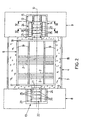
- Fig. 3
- eine Schnittdarstellung gemäß der Schnittlinie III-III in Fig. 2,
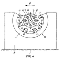
- Fig. 4
- eine Schnittdarstellung gemäß der Schnittlinie IV-IV in Fig. 2,
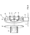
- Fig. 5
- eine Teilansicht der Erfindung gemäß einer zweiten Ausführungsform,
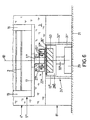
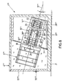
- Fig. 6
- eine Teilquerschnittsdarstellung der Erfindung gemäß einer dritten Ausführungsform,
- Fig. 7
- eine Querschnittsdarstellung der Erfindung gemäß einer vierten Ausführungsform,
- Fig. 8
- eine Querschnittsdarstellung der Erfindung gemäß einer fünften Ausführungsform und
- Fig. 9
- eine Querschnittsdarstellung der Erfindung gemäß einer sechsten Ausführungsform.
- Fig. 1
- a schematic perspective view of the invention according to a first embodiment,
- Fig. 2
- x is a plan view of the invention according to the first embodiment,
- Fig. 3
- a sectional view along the section line III-III in Fig. 2,
- Fig. 4
- a sectional view along the section line IV-IV in Fig. 2,
- Fig. 5
- a partial view of the invention according to a second embodiment,
- Fig. 6
- a partial cross-sectional view of the invention according to a third embodiment,
- Fig. 7
- a cross-sectional view of the invention according to a fourth embodiment,
- Fig. 8
- a cross-sectional view of the invention according to a fifth embodiment and
- Fig. 9
- a cross-sectional view of the invention according to a sixth embodiment.
Eine erste Ausführungsform der Erfindung wird im folgenden unter Bezugnahme
auf die Fig. 1 bis 4 beschrieben. Eine Vorrichtung 1 dient der
naßchemischen und gasförmigen Behandlung von Gegenständen, insbesondere
von Silizium-Scheiben 2, die auch als Wafer bezeichnet werden,
mit einem Medium 3. Die Vorrichtung 1 weist einen mit dem Medium 3
gefüllten oder zu füllenden Behälter 4 auf, in dem eine Träger-Einrichtung
5 zur Aufnahme der Silizium-Scheiben 2 drehbar angeordnet ist. Die Träger-Einrichtung
5 ist in zwei an den Stirnseiten 6, 7 des Behälters 4 angeordneten
Lagerblöcken 8, 9 gelagert. Hierzu sind an den gegenüberliegenden
Seiten der Träger-Einrichtung 5 konzentrisch zu einer im wesentlichen
horizontal verlaufenden Drehachse 10 ein Wellen-Stumpf 11 und ein Wellen-Antriebs-Stumpf
12 vorgesehen, welche zusammen eine Welle bilden.
Der Wellen-Stumpf 11 und der Wellen-Antriebs-Stumpf 12 sind in in den
Lagerblöcken 8 bzw. 9 vorgesehenen Lagern 13 bzw. 14 magnetisch gelagert.
In dem Lagerblock 9 ist ferner eine Antriebs-Einheit 15 zum Drehantrieb
der Welle vorgesehen.A first embodiment of the invention will be hereinafter referred to
to FIGS. 1 to 4 described. A
Der Behälter 4 entspricht den zur Behandlung von Silizium-Scheiben 2
bekannten Behältern und ist aus einem hochkorrosionsbeständigen Kunststoff
gefertigt. Die Behälter 4 können in Form eines Beckens zur Flüssigkeitsbehandlung
oder einer Kammer zur Gas- oder Sprühbehandlung ausgebildet
sein. Zusätzlich ist der Behälter 4 auf seiner Innenseite mit einem
Behälter-Überzug 16 aus einem säureresistenten und chemisch möglichst
inerten Material, insbesondere PTFE oder PVDF versehen. Als Medium 3
werden in Abhängigkeit von dem Bearbeitungsschritt, dem die Silizium-Scheiben
2 unterworfen werden sollen, verschiedene flüssige oder gasförmige
Substanzen verwendet.The
Die Träger-Einrichtung 5 weist jeweils stirnseitig konzentrisch zur Drehachse
10 angeordnete, zueinander parallele Träger-Scheiben 17, 18 auf,
welche entlang ihres Umfangs über parallel zur Drehachse 10 verlaufende
Träger-Stäbe 19 verbunden sind. Die Träger-Stäbe 19 weisen Schlitze 20
auf, in die die Silizium-Scheiben 2 eingreifen und somit gehalten werden. The
Es sind mindestens drei Träger-Stäbe 19 vorgesehen. Es können jedoch
auch zusätzlich weitere Träger-Stäbe 19 vorgesehen sein. Zur Bestückung
der Träger-Einrichtung 5 mit Silizium-Scheiben 2 können ein oder mehrere
Träger-Stäbe 19 entfernt werden. Die in der Träger-Einrichtung 5 fixierten
Silizium-Scheiben 2 sind konzentrisch zur Drehachse 10 und parallel zueinander
angeordnet. Hierdurch wird bei einer Drehung der Träger-Einrichtung
5 um die Drehachse 10 in dem Medium 3 sichergestellt, daß
die Oberflächen der Silizium-Scheiben 2 möglichst gleichmäßig dem Medium
3 ausgesetzt werden und so keine Inhomogenitäten oder Fehlstellen
entstehen. Es können auch andere bekannte, unter anderem eingangs beschriebene
Träger-Einrichtungen verwendet werden. Die Lagerblöcke 8, 9
sind gegenüber einem Maschinen-Boden 21 abgestützt. Die Lager 13 und
14, die im wesentlichen gleich ausgebildet sind, weisen ein konzentrisch
zur Drehachse 10 auf dem Wellen-Stumpf 11 bzw. dem Wellen-Antriebs-Stumpf
12 vorgesehenes erstes Lager-Teil 22 auf. In den Lagerblöcken 8
und 9 sind die ersten Lager-Teile 22 teilweise, insbesondere zu 50 %, umgebende,
durch einen Lager-Spalt 23 voneinander getrennte zweite Lager-Teile
24 vorgesehen. Der Lager-Spalt 23 weist typischerweise eine Breite
von 0,5 bis 10 mm auf.At least three
Das erste Lager-Teil 22 weist den Wellen-Antriebs-Stumpf 12 konzentrisch
umgebende, mit diesem verbundene, entlang der Drehachse 10 benachbart
angeordnete, permanente Ringmagnete 25 auf, wobei jeweils einander benachbart
angeordnete Ringmagnete 25 entweder ein anziehende (entgegengesetzte
magnetische Polung) oder eine abstoßende Kraft (gleiche Pole)
oder eine Kombination aufweisen, so daß entlang der Drehachse 10 beispielsweise
eine Abfolge entsteht S, N; N, S; S, N; N, S; ..., wobei N für
den magnetischen Nordpol und S für den magnetischen Südpol steht. Die
Ringmagnete 25 sind aus SmCo, Sm2CO17 oder NdFeB hergestellt. Letzteres
erreicht die höchsten Energiedichten und einen Remanenzwert von 1,4
Tesla. Es können jedoch auch andere Materialien verwendet werden, die als
Permanentmagnete einen großen Magnetfluß besitzen. Zwischen den
Ringmagneten 25 sind Ringscheiben 26 mit großer Permeabilität vorgesehen,
so daß der magnetische Fluß im Lager-Spalt 23 im wesentlichen senkrecht
zur Drehachse 10 verläuft. Die Ringscheiben 26 weisen typischerweise
eine Dicke von 1 bis 2 mm auf. Das erste Lager-Teil 22 ist zum Schutz
gegen das im Lager-Spalt 23 befindliche Medium 3 mit einem Schutz-Überzug
27 versehen, der aus demselben Material hergestellt ist, wie der
Behälter-Überzug 16. Die Ringmagnete 25, die Ringscheiben 26 sowie die
Stumpfe 11, 12 kommen somit mit dem Medium 3 nicht in Berührung.The
Die zweiten Lager-Teile 24 weisen jeweils eine aus einem supraleitenden
Material gebildete, nach oben offene, parallel zur Drehachse 10 verlaufende
Lager-Halbschale 28 auf, welche zur Aufrechterhaltung des supraleitenden
Zustands von einem Kühl-Mantel 28a umgeben ist, welcher mit einer
Kühl-Einrichtung 29 über eine Wärme-Abführ-Leitung 30 verbunden ist.
Bei dem supraleitenden Material handelt es sich um einen schmelztexturierten
Hochtemperatursupraleiter der Zusammensetzung ReBa2Cu3Ox, wobei
Re=Sm, Nd, Y ist. Die Herstellung schmelztexturierter Hochtemperatursupraleiter
ist in Werfel, Flögel - Delor, Wippich, "YBaCuO Large Scale
Melt Texturing in a Temperature Gradiant", Inst. Phys. Conf. Ser. No. 158,
S. 821 ff., 1997 beschrieben, auf das hiermit verwiesen wird. Die kritische
Stromdichte ist größer als 30 kA/cm2. Die Korngrößen und Korngrenzen
erzeugen im Material besondere Hysterese- und Dämpfungseigenschaften.
Die Hochtemperatursupraleiter-Materialien weisen Kristalle mit einer radial
ähnlichen Textur und eine Sprungtemperatur von bis zu 92 Kelvin
(entspr. - 181 °C) auf, so daß die Supraleiter-Materialien auch durch flüssigen
Stickstoff unterhalb der Sprungtemperatur gehalten werden können. Es
können auch andere Supraleiter-Materialien verwendet werden.The
Die Kühl-Einrichtung 29 weist einen geschlossenen Kryostaten auf, der
nach dem Stirlingprinzip arbeitet. Es ist auch möglich, Kältemaschinen
vorzusehen, die nach dem Gifford-McMahon- oder dem Pulse-Tube-Verfahren
arbeiten. Die Wärme-Abführ-Leitung 30 und der Kühl-Mantel
28a bestehen aus einem sehr gut wärmeleitenden Material, insbesondere
Kupfer. Die Lager-Halbschale 28, der Kühl-Mantel 28a und die Wärme-Abführ-Leitung
30 sind durch einen Zwischen-Raum 31 getrennt von einem
in dem Lagerblock 8 bzw. 9 eingebetteten Zwischen-Gehäuse 32 umgeben.
Zur Erhöhung der Isolation der Lager-Halbschale 28 gegenüber der
Umgebung ist der Zwischen-Raum 31 evakuiert. Der Gas-Restdruck im
Zwischen-Raum 31 ist kleiner als 10-2 Pascal. Zur Absorption von Restgasmolekülen
sind in dem Kühl-Mantel 28a Aktivkohle-Zellen 33 vorgesehen,
die durch die Absorption von Gasmolekülen beim Abkühlen die Qualität
des Vakuums erhöhen. Das zweite Lager-Teil 24 und insbesondere die
Lager-Halbschale 28 weisen einen U-förmigen Querschnitt mit einer Vertiefung
34 auf, die das erste Lager-Teil 22 aufnimmt. Zumindest im Bereich
der Vertiefung 34 weist das Zwischen-Gehäuse 32 einen Schutz-Überzug
35 auf, der aus demselben Material besteht, wie der Schutz-Überzug
27. Zur präzisen Aufrechterhaltung der Form des Lager-Spalts 23
sowie des einen Teil des Zwischen-Raums 31 bildenden Vakuum-Spalts 36
zwischen Schutz-Überzug 35 und Lager-Halbschale 28 ist das Zwischen-Gehäuse
32 in diesem Bereich mit einer Stützschicht 37 versehen, welche
aus einem glasfaserverstärkten oder kohlefaserverstärkten Kunststoff besteht.
Durch diese Anordnung ist es möglich, im Bereich des Lagerspalts
über eine Strecke von wenigen Millimetern eine Isolation für einen Temperaturgradienten
von 250 Kelvin und mehr aufrechtzuerhalten, so daß zum
einen die supraleitende Lager-Halbschale 28 unterhalb der Sprungtemperatur
gehalten wird und zum anderen das Medium 3 im Lager-Spalt 23
nicht einfriert.The
Die benachbart zum Lager 14 angeordnete Antriebs-Einheit 15 weist einen
in einem Stator-Block 38 angeordneten Stator 39 sowie einen mit dem
Wellen-Antriebs-Stumpf 12 einteilig ausgebildeten Rotor 40 auf. Der Stator
39 weist einen im Querschnitt kreissektorförmigen nach oben offenen
Spulen-Kern 41 mit radial zur Drehachse 10 nach innen vorstehenden
Spulen-Zapfen 42, die einteilig mit dem Spulen-Kern 41 ausgebildet sind,
auf. Die Spulen-Zapfen 42 sind von Antriebs-Spulen 43 mit Anschlüssen
44 derart umwickelt, daß die durch die Antriebs-Spulen 43 erzeugten Magnetfelder
im wesentlichen radial zur Drehachse 10 verlaufen. Die Anschlüsse
44 sind in bekannter Weise mit einer Stromversorgungs-/Steuer-Einrichtung
verbunden. Der Rotor 40 weist einen den Stumpf 12 konzentrisch
umgebenden Rotor-Mantel 45 auf, in den permanente Stab-Magnete
46 mit abwechselnder Polung eingesetzt sind, so daß entlang des Umfangs
eine Polungsfolge N, S, N, S, ... entsteht. Die durch die permanenten Stab-Magnete
46 erzeugten Magnetfelder verlaufen im wesentlichen radial zur
Drehachse 10. Als Material für die Stab-Magneten 46 kann dasselbe Material
wie für die Ringmagneten 25 gewählt werden. Der Rotor 40 kann einen
Kurzschlußläufer tragen. Die elektrische Ansteuerung der einander benachbarten
Antriebs-Spulen 43 erfolgt in zeitlicher Abfolge in der Weise, daß
das durch eine Antriebs-Spule 43 erzeugte Magnetfeld den Rotor 40 in einer
Dreh-Richtung 47 abstößt und gleichzeitig das durch die in Dreh-Richtung
47 nachgeordnete Antriebs-Spule 43 erzeugte Magnetfeld den
Rotor 40 anzieht. Auf diese Weise wird ein Drehmoment auf den Rotor 40
übertragen. Dieses Prinzip ist von normalen Drehstrom-Motoren bekannt.
Alternativ kann auch ein anderer Drehstrom-Antrieb verwendet werden,
mit der Besonderheit, daß die Antriebsspule einseitig offen ist, so daß der
Wellen-Antriebs-Stumpf 12 nach oben herausgenommen werden kann.The adjacent to the
Im folgenden wird die Funktionsweise der Vorrichtung 1 beim Betrieb und
insbesondere die Funktionsweise der Lager 13 und 14 beschrieben. Anfänglich
befindet sich die Einheit aus Träger-Einrichtung 5 sowie Wellen-Stumpf
11 und Wellen-Antriebs-Stumpf 12 von einem Roboterarm (nicht
gezeigt) gehalten außerhalb des Behälters 4 und der zweiten Lager-Teile
24. In dieser Position wird die Träger-Einrichtung 5 mit Silizium-Scheiben
2 bestückt, indem ein oder mehrere Stäbe 19 entfernt, die Silizium-Scheiben
2 eingesetzt und anschließend die Silizium-Scheiben 2 durch
Schließen der Träger-Stäbe 19 arretiert werden. Nun wird die Einheit aus
Träger-Einrichtung 5 sowie Wellen-Stumpf 11 und Wellen-Antriebs-Stumpf
12 durch den Roboterarm in die in Fig. 2 gezeigte Position gehoben
und mechanisch in einer sogenannten Einfrier-Position gehalten. Anschließend
werden die Lager-Halbschalen 28 auf eine Temperatur unterhalb der
Sprungtemperatur des supraleitenden Materials abgekühlt. Danach wird die
Träger-Einrichtung 5 durch den Roboterarm freigegeben und "schwebt"
getrennt durch einen Lager-Spalt 23 in den zweiten Lager-Teilen 24. Dies
ist die Folge einer diamagnetischen Wechselwirkung, daß unter dem Einfluß
eines äußeren Magnetfelds in der supraleitenden Lager-Halbschale 28
charakteristische Ströme angeworfen werden, die einen genau entgegengerichteten
Magnetfluß erzeugen. Da die angeworfenen Ströme im wesentlichen
widerstandslos kontinuierlich fließen und selber wiederum ein gegenläufiges
Magnetfeld erzeugen, welches das Magnetfeld der Ringmagnete
25 abstößt, arbeitet das System im wesentlichen leistungslos. Auf
diese Weise stoßen sich das erste Lager-Teil 22 und das zweite Lager-Teil
24 voneinander ab. Veränderungen der Position erzeugen rücktreibende
magnetische Kräfte. Durch die Anordnung mehrerer Ringmagnete 25 entlang
der Drehachse 10 ist die Welle mit einer Steifigkeit sowohl axial als
auch radial bezüglich der Drehachse 10 gelagert. Die Lager 13, 14 besitzen
eine axiale und radiale Lagersteifigkeit von jeweils mehr als 80 N/mm, insbesondere
von über 200 N/mm. Verschiebungen in axialer oder radialer
Richtung erzeugen durch die Fixierung des Magnetflusses im Supraleiter,
dem sogenannten Pinningeffekt, Gegenkräfte mit der Tendenz zur Rückstellung
des ersten Lager-Teils 22 in die Ausgangslage, was als Schlüssel-Schloß-Prinzip
bezeichnet wird. Dies erklärt die hohe Lagersteifigkeit und
automatische Zentrierung des ersten Lager-Teils 22 relativ zum zweiten
Lager-Teil 24. Die Lager 13, 14 dämpfen Schwingungen der Welle in einem
Frequenzbereich von 0,1 Hz bis 1 kHz. Die Lagerung erlaubt Drehzahlen
von bis zu 10000 min-1. Das Gewicht der gelagerten Einheit kann 20
kg und mehr betragen. Durch die berührungslose Lagerung unterliegen die
Lager 13, 14 keinem Verschleiß. Die Lager 13, 14 besitzen eine intrinsische
Dämpfungscharakteristik, da geringe Änderungen des Magnetflusses
etwa in der radialen Magnetisierung der Ringmagnete 25 im supraleitenden
Material Wirbelströme und Bewegungen des Vortexgitters erzeugen. Die
entstehenden Energien werden im Supraleiter freigesetzt und dämpfen somit
Oszillationen der Welle. Die Lager 13, 14 funktionieren passiv, d. h.
ohne elektronische Regelung, und sind damit ausfallsicher und wartungsfrei.
In einer weiteren Methode zum Entfernen der Einheit aus Träger-Einrichtung
5 sowie Stümpfen 11, 12 wird die Kühl-Einrichtung 29 der
Lager-Halbschalen 28 kurzzeitig deaktiviert, nachdem diese Einheit durch
einen Roboterarm erfaßt worden ist. Die Temperatur der Lager-Halbschalen
28 steigt in die Nähe der Sprungtemperatur. Damit einher geht eine Reduktion
der magnetischen Kräfte, ohne daß der Schwebezustand der Einheit
beeinträchtigt wird, welche jetzt leichter aus den zweiten Lager-Teilen 24
herausgehoben werden kann, um die bearbeiteten Silizium-Scheiben 2 zu
entfernen. Der besondere praktische Wert liegt in der einfachen Entfernung
und Wiedereinsetzung der Trägereinrichtung 5 in die Lager-Teile 24. Hierzu
bedarf es keiner Schalt- oder Regelfunktionen im Lagerbereich.In the following, the operation of the
Durch die berührungs- und reibungsfrei arbeitenden Lager 13, 14 wird die
sonst durch Lagerabrieb entstehende Zahl von Fremdpartikeln im Medium
3, welche die Qualität der Silizium-Scheiben 2 beeinträchtigen, stark reduziert.
Somit kann für die Silizium-Scheiben 2 eine rotierende Behandlung
durchgeführt werden, welche den Vorteil einer hohen Homogenität der ablaufenden
flüssigen, festen oder gasförmigen Prozesse auf der Oberfläche
der Silizium-Scheiben 2 besitzt. Ein weiterer Vorteil der Drehung der Silizium-Scheiben
2 liegt in der Vermeidung von Bläschenhaftung auf der
Oberfläche, welche sonst dazu führt, daß die flüssigen oder gasförmigen
Medien an dieser Stelle die Oberfläche nicht angreifen können und Fehlstellen
entstehen.Through the contact and
Im folgenden wird unter Bezugnahme auf Fig. 5 eine zweite Ausführungsform
der Erfindung beschrieben. Identische Teile werden mit denselben
Bezugszeichen wie in der ersten Ausführungsform versehen; verschiedene,
jedoch funktionell gleichartige Teile werden mit denselben Bezugszeichen
mit einem hochgesetzten Strich versehen. Ansonsten wird auf die Beschreibung
zum ersten Ausführungsbeispiel verwiesen. Die zweite Ausführungsform
unterscheidet sich von der ersten Ausführungsform lediglich
durch den Aufbau der Antriebs-Einheit 15'. Am in Fig. 5 rechten Ende des
Wellen-Antriebs-Stumpfes 12' ist eine senkrecht zur Drehachse 10 verlaufende
Hysterese-Scheibe 48 aus einem Material mit einer ausgeprägten Hysterese-Kurve
vorgesehen. Benachbart hierzu ist eine über eine Stütze 49
gegenüber dem Maschinen-Boden 21 abgestützte, konzentrisch zur Drehachse
10 verlaufende, als Spulen-Ring 50 ausgebildete Spulen-Einheit mit
Drehstromwicklung vorgesehen. Der Spulen-Ring 50 weist einen Ring-Kern
51 auf, welcher an verschiedenen, gleichmäßig über den Ring-Kern
51 verteilten Positionen mit Antriebs-Spulen 43' umwickelt ist. Zum Schutz
vor dem Medium 3 sind Ring-Kern 51 und Antriebs-Spulen 43' mit einem
Schutz-Überzug 52 versehen, welcher aus demselben Material gefertigt ist,
wie der Schutz-Überzug 27. Selbiges gilt für den Stumpf 12' und die Scheibe
48. Die Funktionsweise eines derartigen Antriebs ist bekannt. Beim
Ummagnetisieren von hysteretischem Eisen tritt zwischen erregender magnetischer
Feldstärke und magnetischer Induktion eine Phasenverschiebung
auf. Diese hängt mit der geometrischen Form der Hysterese-Schleife zusammen
und hängt darüber hinaus von der Amplitude der Wechselerregung
ab. Dieses Prinzip macht sich der Hysterese-Antrieb gemäß Fig. 5 zunutze.
Die Hysterese-Scheibe 48 ist als massive Scheibe ausgebildet und läßt sich
gut ummanteln. Es ist auch möglich, die Hysterese-Scheibe 48 als Rohr
auszubilden. Im Anlauf verhält sich der Hysterese-Antrieb wie ein Asynchronmotor;
ist die Nenndrehzahl erreicht, ergibt sich ein Synchronlauf.
Der Vorteil dieses Antriebs besteht vor allem darin, daß keine Stab-Magneten
46 benötigt werden und ein Synchronantrieb aufgebaut werden kann.In the following, with reference to Fig. 5, a second embodiment
of the invention. Identical parts become the same
Numeral provided as in the first embodiment; various,
however, functionally similar parts are denoted by the same reference numerals
provided with a prime bar. Otherwise, the description
refer to the first embodiment. The second embodiment
differs from the first embodiment only
by the structure of the drive unit 15 '. At the right in Fig. 5 end of
Shaft drive stump 12 'is a perpendicular to the axis of
Im folgenden wird unter Bezugnahme auf Fig. 6 eine dritte Ausführungsform
der Erfindung beschrieben. Identische Teile erhalten dieselben Bezugszeichen
wie in der ersten Ausführungsform; verschiedene, jedoch
funktionell gleichwertige Teile erhalten dieselben Bezugszeichen mit zwei
hochgesetzten Strichen. Ansonsten wird auf die Beschreibung des ersten
Ausführungsbeispiels verwiesen. Der zentrale Unterschied der dritten Ausführungsform
gegenüber der ersten Ausführungsform besteht darin, daß die
Drehachse 10 nicht horizontal, sondern vertikal verläuft. In dem Lagerblock
8" ist das zweite Lagerteil 24" vorgesehen, welches wie das Lager-Teil
24 der ersten Ausführungsform aufgebaut ist. Der einzige Unterschied
besteht darin, daß anstelle einer Lager-Halbschale 28 eine Lager-Scheibe
53 aus einem supraleitenden Material vorgesehen ist. Oberhalb dieser ist
der Behälter 4" angeordnet, in dem die Träger-Einrichtung 5" mit vertikal
verlaufender Drehachse 10 angeordnet ist. Am in Fig. 6 unteren Ende der
Träger-Einrichtung 5" ist das erste Lager-Teil 22" vorgesehen, welches
konzentrisch zueinander verlaufende, parallel zu der Drehachse 10 magnetisierte
Ringmagnete 25" aufweist. Es können mehr als zwei konzentrische
Ringmagnete 25" vorgesehen sein. Die Magnetisierung jeweils benachbarter
Ringmagnete 25" ist abwechselnd. Zwischen den Ringmagneten 25"
können zusätzlich Ringscheiben 26" mit geringer Permeabilität vorgesehen
sein. Das Lager 13" weist sowohl axiale als auch radiale Lagersteifigkeit
auf. Zum Antrieb der Träger-Einrichtung 5" ist an dem in Fig. 6 nicht dargestellten
oberen Ende der Träger-Einrichtung 5" eine Antriebs-Einheit 15'
vorgesehen, wie sie in der zweiten Ausführungsform beschrieben ist. Zum
Entfernen der Träger-Einheit 5" aus dem Behälter 4" wird der Spulen-Ring
50 quer zur Drehachse 10 verschwenkt, so daß die Träger-Einrichtung 5"
nach oben aus dem Behälter 4" gezogen werden kann.In the following, referring to FIG. 6, a third embodiment will be described
of the invention. Identical parts are given the same reference numerals
as in the first embodiment; different, however
functionally equivalent parts are given the same reference numerals with two
raised strokes. Otherwise, the description of the first
Reference example. The central difference of the third embodiment
compared to the first embodiment is that the
Es ist auch möglich, den Achsstumpf 11' zu verlängern und eine andere
Antriebs-Einheit, wie z.B. in der ersten Ausführungsform, vorzusehen.
Damit kann die Träger-Einrichtung 5" nach oben offen gehalten werden
und erlaubt eine stirnseitige Beladung mit einem separaten Carrier-Käfig,
z.B. aus zwei Halbschalen. Die Halbschalen besitzen geschlitzte, axiale
Stäbe, in die die Silizium-Scheiben 2 eingefügt sind. Die beiden Halbschalen
werden aufeinander gepreßt, axial in die Träger-Einrichtung 5' von
oben hineingeschoben und in axialen Führungen fixiert.It is also possible to extend the stub axle 11 'and another
Drive unit, such as in the first embodiment.
Thus, the support means 5 "can be kept open at the top
and allows a frontal loading with a separate carrier cage,
e.g. from two half-shells. The half-shells have slotted, axial
Rods in which the
Die Lager 13, 14 der ersten Ausführungsform und das Lager 13" der dritten
Ausführungsform können selbstverständlich miteinander kombiniert werden.
Auf diese Weise kann die Lagersteifigkeit in radialer und axialer
Richtung erhöht werden und die Drehachse einen Winkel zwischen 0 und
90 ° gegenüber der Horizontalen, d. h. eine beliebige Position zwischen
einer horizontalen Anordnung und einer vertikalen Anordnung, einnehmen.
Im folgenden wird unter Bezugnahme auf Fig. 7 eine vierte Ausführungsform
der Erfindung beschrieben. Identische Teile erhalten dieselben Bezugszeichen
wie in der ersten Ausführungsform, auf deren Beschreibung
hiermit verwiesen wird. Konstruktiv unterschiedliche, jedoch funktionell
gleichartige Teile erhalten dieselben Bezugszeichen mit drei hochgesetzten
Strichen. Die Vorrichtung 1"' weist einen Lagerblock 9"' auf, in dem konzentrisch
zu einer Drehachse 10"' ein ringzylindrisches Lager-Teil 24"' und
eine ringzylindrische Antriebs-Einheit 15"' vorgesehen sind. Beide umgeben
einen als Sackloch ausgebildeten, ringzylindrischen Lager-Raum 54, in
dem der Wellen-Antriebs-Stumpf 12"' mittig angeordnet ist. Die Drehachse
10"' ist gegenüber der Horizontalen um einen Winkel α geneigt, für den
gilt: 0° < α < 90° und insbesondere 5° < α < 30° und höchst vorteilhafterweise
α = 15°. Die Träger-Einrichtung 5"' weist einen parallel zur Drehachse
10"' von außen einschiebbaren Hilfs-Träger-Korb 60 auf, der die Silizium-Scheiben
2 aufnimmt. Der Korb 60 kann endseitig in die Träger-Einrichtung
5'" eingeschoben bzw. aus dieser herausgenommen werden. The
Die Träger-Einrichtung 5"' ist konzentrisch zur Drehachse 10"' angeordnet
und mit dem Wellen-Antriebs-Stumpf 12"' verbunden. An dem dem Wellen-Antriebs-Stumpf
12"' abgewandten Ende der Träger-Einrichtung 5"' ist
umfangsseitig das Lager-Teil 22"' vorgesehen. Das Lager-Teil 22"' weist
entlang des Umfangs benachbart zueinander angeordnete Permanentmagnete
55 mit radialer Ausrichtung auf. In Fig. 7 unterhalb des Lager-Teils
22"' ist der Lagerblock 8"' mit dem Lager-Teil 24"' vorgesehen. Das Lager-Teil
24"' ist kreissegmentförmig ausgebildet und umgibt das Lager-Teil 22"'
teilweise. Durch das Lager 13"' wird die Träger-Einrichtung 5"' in vertikaler
Richtung abgestützt und quer dazu stabilisiert. Der Behälter 4"' weist
eine über ein Scharnier 56 mit dem Lagerblock 8"' verbundene vertikale
Seitenwand 57 und eine mit dem oberen Ende des Lagerblocks 9"' über ein
Scharnier 58 verbundene Seitenwand 59 auf. Die Seitenwände 57 und 59
sind nach außen verschwenkbar.The
Im folgenden wird der Betrieb der Vorrichtung 1"' genauer beschrieben.
Zum Einsetzen der Träger-Einrichtung 5"' werden die Seitenwände 57 und
59 aufgeklappt, wodurch der Lager-Raum 54 zugänglich wird. Der Wellen-Antriebs-Stumpf
12"' wird leicht gegenüber der Horizontalen geneigt in den
Lager-Raum 54 eingeführt. Anschließend wird das supraleitende Lager-Teil
24"' abgekühlt, bis dieses supraleitend wird. Aufgrund des oben beschriebenen
Mechanismusses ist die Träger-Einrichtung 5"' nun reibungslos
gelagert. Zur Abstützung der Träger-Einrichtung 5"' wird auch das Lager-Teil
24"' des Lagers 13"' unter die Sprungtemperatur abgekühlt. Vorteilhaft
an dieser Anordnung ist die Möglichkeit der frontseitigen Beschickung der
Träger-Einrichtung 5"'. Die gesamte Träger-Einrichtung 5"' einschließlich
des Korbs 60 kann aus der Vorrichtung 1 entlang der Drehachse 10"' entnommen
werden und einer gründlichen Reinigung zugeführt werden. In the following, the operation of the
Im folgenden wird unter Bezugnahme auf Fig. 8 eine fünfte Ausführungsform
der Erfindung beschrieben. Identische Teile erhalten dieselben Bezugszeichen
wie in der ersten Ausführungsform, auf deren Beschreibung
hiermit verwiesen wird. Konstruktiv unterschiedliche, jedoch funktionell
gleichartige Teile erhalten dieselben Bezugszeichen mit vier hochgesetzten
Strichen. Der wesentliche Unterschied der Vorrichtung 1"" gegenüber der
Vorrichtung 1 besteht darin, daß die Träger-Einrichtung 5"" nicht an ihren
beiden axialen Enden gelagert ist, sondern lediglich auf einer Seite. Hierfür
sind benachbart zu der Träger-Einrichtung 5"" in dem Lager-Block 9"" jeweils
zueinander benachbart das Lager 13"", die Antriebs-Einheit 15"" und
das Lager 14"" vorgesehen. Die zweiten Lager-Teile 24"" sowie der Stator
39"" umgeben den Wellen-Antriebs-Stumpf 12"" ringzylindrisch. Der Behälter
4"" weist eine über ein Scharnier 56"" verbundene und verschwenkbare
vertikale Seitenwand 57"" auf. Die Drehachse 10"" ist gegenüber der
Horizontalen um einen Winkel α von ungefähr 15° geneigt.Hereinafter, a fifth embodiment will be described with reference to FIG
of the invention. Identical parts are given the same reference numerals
as in the first embodiment, to the description thereof
Reference is hereby made. Structurally different, but functional
like parts are given the same reference numerals with four superscripts
Strokes. The main difference of the
Beim Betrieb der Vorrichtung 1"" kann die mit Silizium-Scheiben 2 beschickte
Träger-Einrichtung 5"" in dem Behälter 5"" um die Drehachse 10""
gedreht werden. Der Vorteil der Ausführungsform besteht darin, daß die
Silizium-Scheiben entlang der Drehachse 10"" entnommen werden können.
Darüber hinaus kann die Einheit aus Träger-Einrichtung 5"" und Wellen-Antriebs-Stumpf
12"" ebenfalls entlang der Drehachse 10"" zu Reinigungsoder
Reparaturzwecken entnommen werden. Eine separate Abstützung wie
durch das Lager 13"' in der vierten Ausführungsform ist nicht erforderlich.During operation of the
Im folgenden wird unter Bezugnahme auf Fig. 9 eine sechste Ausführungsform
der Erfindung beschrieben. Identische Teile erhalten dieselben Bezugszeichen
wie bei der fünften, in Fig. 8 dargestellten Ausführungsform,
auf deren Beschreibung hiermit verwiesen wird. Konstruktiv unterschiedliche,
jedoch funktionell gleichartige Teile erhalten dieselben Bezugszeichen
mit fünf hochgesetzten Strichen. Der Aufbau der Lagerteile 24"" sowie der
Antriebseinheit 15"" entspricht dem Aufbau gemäß der fünften Ausführungsform.
Selbiges gilt für den Aufbau des Rotors 40 mit der Ausnahme,
daß dieser von einem resistenten zylinderförmigen Mantel 61 aus Kunststoff
umgeben ist. Im Unterschied zur fünften Ausführungsform ist die Anordnung
des Rotors 40 derart gewählt, daß die Drehachse 10""' vertikal
verläuft. Der Lagerblock 9""' weist an seinem unteren Ende eine Ablauf-Öffnung
62 auf, die mit dem Ringraum zwischen dem Mantel 61 und den
Lager-Teilen 24"" bzw. der Antriebs-Einheit 15"" verbunden ist. Die mit
dem Rotor 40 verbundene Träger-Scheibe 18""' verläuft im wesentlichen
horizontal und dient mit ihrer Oberseite als Auflage für eine Silizium-Scheibe
2. Der Behälter 4""', der als Deckel 63 ausgebildet ist, ist seitlich
und oberhalb der Silizium-Scheibe 2 angeordnet. Es ist selbstverständlich
möglich, die Vorrichtung 1""' auch ohne den Behälter 4""' zu betreiben. Im
Deckel 63 ist mittig eine Zuführ-Leitung 64 angeordnet, die in dem vom
Deckel 63 begrenzten Raum eine Düse 65 aufweist. Seitlich unterhalb der
Silizium-Scheibe 2 weist der Deckel 63 einen Deckelrand 66 mit einer Abführ-Leitung
67 auf.In the following, with reference to Fig. 9, a sixth embodiment
of the invention. Identical parts are given the same reference numerals
as in the fifth embodiment shown in FIG. 8,
to the description of which reference is hereby made. Constructively different,
However, functionally similar parts receive the same reference numerals
with five raised dashes. The structure of the bearing
Im folgenden wird die Funktionsweise der Vorrichtung 1""' gemäß der
sechsten Ausführungsform beschrieben. Die Träger-Scheibe 18""' ist wie
bei der fünften Ausführungsform reibungsfrei drehantreibbar gelagert. Zum
Auftragen von Fotolack auf die Silizium-Scheibe 2 wird ein Tropfen Fotolack
durch die Düse 5 mittig auf die rotierende Silizium-Scheibe 2 aufgebracht.
In Folge der Zentrifugalkräfte verteilt sich der Fotolack schnell,
dünn und homogen auf der Oberfläche der Silizium-Scheibe 2. Überschüssiger
Lack wird durch die Abführ-Leitung 67 und die Ablauf-Öffnung 62
abgeführt. Die Vorrichtung 1""' kann darüber hinaus für die in den vorausgehenden
Ausführungsformen beschriebenen Ätz- und Reinigungsprozesse
verwendet werden. Darüber hinaus kann die Silizium-Scheibe 2 in der Vorrichtung
1""' trocken zentrifugiert werden.In the following, the operation of the
Ferner kann die Vorrichtung 1'"" zur Prüfung der Fehlerfreiheit der Kristallund
Oberflächenstruktur der Silizium-Scheibe 2 verwendet werden. Durch
die Art der Lagerung des Rotors 40 ist es möglich, die Silizium-Scheibe 2
sehr schnell auf sehr hohe Drehzahlen, wie sie eingangs beschrieben sind,
zu beschleunigen. Haarrisse und andere Fehlstellen in der Kristallstruktur
der Silizium-Scheibe 2 wachsen bei entsprechend hohen Zentrifugalkräften
und können so einfach ermittelt werden. Gegebenenfalls führen diese Fehlstellen
sogar zum Bruch der Scheibe 2. Die Vorrichtung 1""' kann somit
auch ohne den Einsatz eines Behandlungs-Mediums 3 zur Qualitätskontrolle
verwendet werden. Diese Form der Qualitätskontrolle ist auch mit
den Vorrichtungen gemäß der ersten bis fünften Ausführungsform möglich.Further, the device 1 '"" for checking the accuracy of the crystal and
Surface structure of the
Claims (14)
- A device (1; 1'; 1"; 1"'; 1"") for treating objects, in particular silicon wafers (2), with a fluid (3), comprisinga) a container (4; 4"; 4"'; 4"") for accommodation of a fluid (3) characterized in thatb) a rotatable carrying arrangement (5; 5"; 5"'; 5""), which is at least partially disposed in the container (4; 4"; 4"'; 4""), serving for accommodation of the objects to be treated andc) a rotatably drivable shaft, which is run on at least one bearing (13, 14; 13"; 13"', 14"'; 13"", 14"") and joined to the carrying arrangement (5; 5"; 5"'; 5"") is provided,d) with the at least one bearing (13, 14; 13"; 13"', 14"'; 13"", 14"") includingi) a first bearing member (22; 22"; 22"') joined to the shaft; andii) a second bearing member (24; 24"; 24"'; 24"") in vicinity to the first bearing member (22; 22"; 22"'), containing superconductive material;iii) with the first bearing member (22; 22", 22"') being kept spaced from the second bearing member (24; 24"; 24"'; 24"") by magnetic forces.
- A device (1) according to claim 1, characterized in that the second bearing member (24) comprises a bearing shell (28) of superconductive material.
- A device (1) according to one of the preceding claims, characterized in that the first bearing member (22) has permanent ring magnets (25).
- A device (1) according to claim 3, characterized in that respectively adjacent ring magnets (25) have opposed magnetic poles.
- A device (1") according to claim 1, characterized in that the second bearing member (24") has a plane bearing disk (53) of superconductive material.
- A device (1") according to claim 5, characterized in that the first bearing member (22") comprises permanent ring magnets (25") which are disposed concentrically of each other.
- A device (1; 1'; 1", 1"'; 1"") according to one of the preceding claims, characterized in that a driving unit (15; 15'; 15"'; 15"") is provided for actuation of the shaft.
- A device (1; 1"; 1"'; 1"") according to claim 7, characterized in that the driving unit (15; 15"; 15"") comprises a coil core (41), which encircles the shaft at least partially.
- A device (1') according to claim 7, characterized in that the driving unit (15') includes a hysteresis disk (48), which is joined to the shaft, and a stationary coil unit for the generation of a magnetic field which interacts with the hysteresis disk (48) for actuation of the shaft.
- A device (1; 1'; 1"; 1"'; 1"") according to one of the preceding claims, characterized in that the first bearing member (22; 22"; 22"') and/or the second bearing member (24; 24"; 24"'; 24"") and/or the container (4; 4"; 4"'; 4"") and/or the shaft are provided with a coating (16, 27, 35; 52; 27", 35") that is resistant to the fluid (3).
- A device (1; 1'; 1"; 1"'; 1"") according to one of the preceding claims, characterized in that the first bearing member (22; 22"; 22"') is removable from the second bearing member (24; 24"; 24"'; 24"").
- A device (1; 1'; 1"; 1"'; 1"") according to one of the preceding claims, characterized in that the shaft and a horizontal line make a freely selectable angle α to which applies 0° ≤ α ≤ 90°, in particular 5° ≤ α ≤30°and by special advantage α ≈ 15°.
- A device (1""') according to claim 1, characterized in that the shaft is substantially vertical and the carrying arrangement (5""') comprises a substantially horizontal support disk (18""').
- A device (1""') according to claim 13, characterized in that the support disk (18""') serves as a support for an object to be treated.
Applications Claiming Priority (5)
| Application Number | Priority Date | Filing Date | Title |
|---|---|---|---|
| DE19918922 | 1999-04-27 | ||
| DE19918922 | 1999-04-27 | ||
| DE19959299A DE19959299A1 (en) | 1999-04-27 | 1999-12-09 | Treatment device for silicon wafers |
| DE19959299 | 1999-12-09 | ||
| PCT/EP2000/003351 WO2000065637A2 (en) | 1999-04-27 | 2000-04-13 | Device for treating silicon wafers |
Publications (2)
| Publication Number | Publication Date |
|---|---|
| EP1173883A2 EP1173883A2 (en) | 2002-01-23 |
| EP1173883B1 true EP1173883B1 (en) | 2003-10-01 |
Family
ID=26053088
Family Applications (1)
| Application Number | Title | Priority Date | Filing Date |
|---|---|---|---|
| EP00936696A Expired - Lifetime EP1173883B1 (en) | 1999-04-27 | 2000-04-13 | Device for treating silicon wafers |
Country Status (7)
| Country | Link |
|---|---|
| US (1) | US7048824B1 (en) |
| EP (1) | EP1173883B1 (en) |
| JP (1) | JP2004507068A (en) |
| CN (1) | CN1349655A (en) |
| AT (1) | ATE251340T1 (en) |
| AU (1) | AU5210300A (en) |
| WO (1) | WO2000065637A2 (en) |
Families Citing this family (11)
| Publication number | Priority date | Publication date | Assignee | Title |
|---|---|---|---|---|
| JP3808709B2 (en) * | 2000-07-19 | 2006-08-16 | 大日本スクリーン製造株式会社 | Substrate processing equipment |
| JP4026750B2 (en) | 2002-04-24 | 2007-12-26 | 東京エレクトロン株式会社 | Substrate processing equipment |
| JP4486649B2 (en) * | 2004-10-28 | 2010-06-23 | 東京エレクトロン株式会社 | Liquid processing equipment |
| US8471254B2 (en) * | 2005-12-27 | 2013-06-25 | Hana Microdisplay Technologies, Inc. | Liquid crystal cells with uniform cell gap and methods of manufacture |
| CN101432622B (en) * | 2006-03-03 | 2013-05-29 | 国立大学法人新澙大学 | Quantitative evaluation device and method of atom vacancy existing in silicon wafer |
| JP5276347B2 (en) * | 2007-07-03 | 2013-08-28 | 国立大学法人 新潟大学 | Quantitative evaluation apparatus for atomic vacancy existing in silicon wafer, method thereof, method for manufacturing silicon wafer, and thin film vibrator |
| CN101217108B (en) * | 2008-01-02 | 2010-06-09 | 株洲南车时代电气股份有限公司 | A chip table top etching device |
| US20100038498A1 (en) * | 2008-08-18 | 2010-02-18 | Skedco, Inc. | Configurable anchor point and modular kit for an anchor point |
| US20120098371A1 (en) * | 2010-10-22 | 2012-04-26 | Spinlectrix Inc. | Stabilization of rotating machinery |
| JP5715444B2 (en) * | 2011-02-28 | 2015-05-07 | 東京エレクトロン株式会社 | Mounting device |
| DE102019135182A1 (en) * | 2019-12-19 | 2021-06-24 | Oerlikon Surface Solutions Ag, Pfäffikon | Holding device for holding a substrate |
Family Cites Families (20)
| Publication number | Priority date | Publication date | Assignee | Title |
|---|---|---|---|---|
| CH469404A (en) * | 1968-01-26 | 1969-02-28 | Ebauches Sa | Frequency divider |
| US4300581A (en) * | 1980-03-06 | 1981-11-17 | Thompson Raymon F | Centrifugal wafer processor |
| EP0238908A1 (en) * | 1986-03-19 | 1987-09-30 | Siemens Aktiengesellschaft | Cryosorption pump for thermal vacuum insulation of the rotor of an electric machine provided with a supra-conducting field coil |
| DE3808331A1 (en) * | 1988-03-12 | 1989-09-28 | Kernforschungsanlage Juelich | MAGNETIC STORAGE WITH PERMANENT MAGNETS TO RECEIVE THE RADIAL BEARING FORCES |
| JPH0558777A (en) * | 1991-08-27 | 1993-03-09 | Canon Inc | Thin film forming device |
| JPH05238683A (en) * | 1992-02-28 | 1993-09-17 | Ebara Corp | Magnetically levitated elevator |
| US5398481A (en) * | 1992-05-19 | 1995-03-21 | Ebara Corporation | Vacuum processing system |
| JPH0758036A (en) * | 1993-08-16 | 1995-03-03 | Ebara Corp | Thin film fabrication apparatus |
| JP3961032B2 (en) * | 1993-12-13 | 2007-08-15 | シーメンス アクチエンゲゼルシヤフト | Magnetic bearing device for rotor shaft |
| EP0695027A4 (en) * | 1994-01-25 | 1997-10-08 | Kanagawa Kagaku Gijutsu Akad | Magnetic levitation device |
| JPH081475A (en) * | 1994-06-22 | 1996-01-09 | Nippon Seiko Kk | Turntable device |
| US5554583A (en) * | 1994-09-08 | 1996-09-10 | Hull; John R. | Permanent magnet design for high-speed superconducting bearings |
| DE19503695C2 (en) * | 1995-02-04 | 1997-02-27 | Roland Man Druckmasch | Protection for a printing press |
| US5747426A (en) * | 1995-06-07 | 1998-05-05 | Commonwealth Research Corporation | High performance magnetic bearing systems using high temperature superconductors |
| TW331652B (en) * | 1995-06-16 | 1998-05-11 | Ebara Corp | Thin film vapor deposition apparatus |
| JP2001524259A (en) * | 1995-07-10 | 2001-11-27 | シーヴィシー、プラダクツ、インク | Programmable ultra-clean electromagnetic substrate rotating apparatus and method for microelectronics manufacturing equipment |
| JP3672416B2 (en) * | 1997-06-27 | 2005-07-20 | 株式会社荏原製作所 | Spin processing equipment |
| JP3847935B2 (en) * | 1998-01-09 | 2006-11-22 | キヤノン株式会社 | Method for removing porous region and method for manufacturing semiconductor substrate |
| DE19847347C2 (en) * | 1998-10-14 | 2001-03-29 | Ldt Gmbh & Co | Magnetic bearings |
| TW466576B (en) * | 1999-06-15 | 2001-12-01 | Ebara Corp | Substrate processing apparatus |
-
2000
- 2000-04-13 WO PCT/EP2000/003351 patent/WO2000065637A2/en active IP Right Grant
- 2000-04-13 EP EP00936696A patent/EP1173883B1/en not_active Expired - Lifetime
- 2000-04-13 JP JP2000614487A patent/JP2004507068A/en active Pending
- 2000-04-13 AU AU52103/00A patent/AU5210300A/en not_active Abandoned
- 2000-04-13 US US09/959,495 patent/US7048824B1/en not_active Expired - Fee Related
- 2000-04-13 AT AT00936696T patent/ATE251340T1/en not_active IP Right Cessation
- 2000-04-13 CN CN00806788A patent/CN1349655A/en active Pending
Also Published As
| Publication number | Publication date |
|---|---|
| JP2004507068A (en) | 2004-03-04 |
| EP1173883A2 (en) | 2002-01-23 |
| WO2000065637A2 (en) | 2000-11-02 |
| ATE251340T1 (en) | 2003-10-15 |
| AU5210300A (en) | 2000-11-10 |
| US7048824B1 (en) | 2006-05-23 |
| CN1349655A (en) | 2002-05-15 |
| WO2000065637A3 (en) | 2001-04-12 |
Similar Documents
| Publication | Publication Date | Title |
|---|---|---|
| EP1173883B1 (en) | Device for treating silicon wafers | |
| EP1313959B1 (en) | Magnetic bearing for suspending a rotating shaft using high tc superconducting material | |
| EP1320693B1 (en) | Magnetic bearing | |
| EP1038114B1 (en) | Magnetic bearing and its use | |
| EP0598183A1 (en) | Turbogenerator set | |
| DE3810197A1 (en) | PLASMA MACHINING DEVICE | |
| DE4232869C2 (en) | Superconducting bearing unit and method for its operation | |
| DE19727550C2 (en) | Magnetic bearing of a rotor in a stator | |
| DE4436831A1 (en) | Unit for magnetic orientation of rotor shaft | |
| DE19643844C1 (en) | Superconducting magnetic bearing of modular construction | |
| DE19526291A1 (en) | Vacuum centrifuge useful esp. for prodn. of staple fibre yarns | |
| DE112012000596B4 (en) | Winding and twisting device of a ring spinning or ring twisting machine as well as ring spinning and ring twisting process | |
| EP2850723B1 (en) | Scalable device and arrangement for storing and releasing energy | |
| DE19959299A1 (en) | Treatment device for silicon wafers | |
| DE4234524C2 (en) | Hybrid storage unit | |
| EP0510256B1 (en) | Method and apparatus for crushing, dispersing, wetting and mixing of pumpable, non-magnetic multiphase mixtures | |
| WO1996018805A1 (en) | Turbine with shaft mounted on magnetic bearings | |
| DE10358341B4 (en) | Device for storing a coolant supply for superconducting machines | |
| EP1650441B1 (en) | Low vibration vacuum pump | |
| WO2008006699A1 (en) | Synchronous machine having magnetic bearing excited by the rotor | |
| DE19938079C1 (en) | Superconducting magnetic bearing, e.g. for a flywheel energy storage unit, has a rotor disk of coaxial radially clamped permanent magnet rings forming gaps with high temperature superconductor stator rings | |
| DE19715356A1 (en) | Magnetic bearing for fast-rotating components e.g. centrifuge or flywheel | |
| DE10120623B4 (en) | Centrifuge with a rotor provided for receiving centrifuging | |
| DE102021002523B4 (en) | Device and method for winding and twisting fiber material in ring spinning or ring twisting machines | |
| JPH04165119A (en) | Superconductive bearing device |
Legal Events
| Date | Code | Title | Description |
|---|---|---|---|
| PUAI | Public reference made under article 153(3) epc to a published international application that has entered the european phase |
Free format text: ORIGINAL CODE: 0009012 |
|
| 17P | Request for examination filed |
Effective date: 20011016 |
|
| AK | Designated contracting states |
Kind code of ref document: A2 Designated state(s): AT BE CH CY DE DK ES FI FR GB GR IE IT LI LU MC NL PT SE |
|
| AX | Request for extension of the european patent |
Free format text: AL;LT;LV;MK;RO;SI |
|
| GRAH | Despatch of communication of intention to grant a patent |
Free format text: ORIGINAL CODE: EPIDOS IGRA |
|
| GRAS | Grant fee paid |
Free format text: ORIGINAL CODE: EPIDOSNIGR3 |
|
| GRAA | (expected) grant |
Free format text: ORIGINAL CODE: 0009210 |
|
| AK | Designated contracting states |
Kind code of ref document: B1 Designated state(s): AT BE CH CY DE DK ES FI FR GB GR IE IT LI LU MC NL PT SE |
|
| PG25 | Lapsed in a contracting state [announced via postgrant information from national office to epo] |
Ref country code: FI Free format text: LAPSE BECAUSE OF FAILURE TO SUBMIT A TRANSLATION OF THE DESCRIPTION OR TO PAY THE FEE WITHIN THE PRESCRIBED TIME-LIMIT Effective date: 20031001 Ref country code: IT Free format text: LAPSE BECAUSE OF FAILURE TO SUBMIT A TRANSLATION OF THE DESCRIPTION OR TO PAY THE FEE WITHIN THE PRESCRIBED TIME-LIMIT;WARNING: LAPSES OF ITALIAN PATENTS WITH EFFECTIVE DATE BEFORE 2007 MAY HAVE OCCURRED AT ANY TIME BEFORE 2007. THE CORRECT EFFECTIVE DATE MAY BE DIFFERENT FROM THE ONE RECORDED. Effective date: 20031001 Ref country code: CY Free format text: LAPSE BECAUSE OF FAILURE TO SUBMIT A TRANSLATION OF THE DESCRIPTION OR TO PAY THE FEE WITHIN THE PRESCRIBED TIME-LIMIT Effective date: 20031001 Ref country code: IE Free format text: LAPSE BECAUSE OF FAILURE TO SUBMIT A TRANSLATION OF THE DESCRIPTION OR TO PAY THE FEE WITHIN THE PRESCRIBED TIME-LIMIT Effective date: 20031001 Ref country code: NL Free format text: LAPSE BECAUSE OF FAILURE TO SUBMIT A TRANSLATION OF THE DESCRIPTION OR TO PAY THE FEE WITHIN THE PRESCRIBED TIME-LIMIT Effective date: 20031001 |
|
| REG | Reference to a national code |
Ref country code: GB Ref legal event code: FG4D Free format text: NOT ENGLISH |
|
| REG | Reference to a national code |
Ref country code: CH Ref legal event code: EP |
|
| GBT | Gb: translation of ep patent filed (gb section 77(6)(a)/1977) | ||
| REG | Reference to a national code |
Ref country code: IE Ref legal event code: FG4D Free format text: GERMAN |
|
| REF | Corresponds to: |
Ref document number: 50003903 Country of ref document: DE Date of ref document: 20031106 Kind code of ref document: P |
|
| PG25 | Lapsed in a contracting state [announced via postgrant information from national office to epo] |
Ref country code: GR Free format text: LAPSE BECAUSE OF FAILURE TO SUBMIT A TRANSLATION OF THE DESCRIPTION OR TO PAY THE FEE WITHIN THE PRESCRIBED TIME-LIMIT Effective date: 20040101 Ref country code: DK Free format text: LAPSE BECAUSE OF FAILURE TO SUBMIT A TRANSLATION OF THE DESCRIPTION OR TO PAY THE FEE WITHIN THE PRESCRIBED TIME-LIMIT Effective date: 20040101 Ref country code: SE Free format text: LAPSE BECAUSE OF FAILURE TO SUBMIT A TRANSLATION OF THE DESCRIPTION OR TO PAY THE FEE WITHIN THE PRESCRIBED TIME-LIMIT Effective date: 20040101 |
|
| PG25 | Lapsed in a contracting state [announced via postgrant information from national office to epo] |
Ref country code: ES Free format text: LAPSE BECAUSE OF FAILURE TO SUBMIT A TRANSLATION OF THE DESCRIPTION OR TO PAY THE FEE WITHIN THE PRESCRIBED TIME-LIMIT Effective date: 20040112 |
|
| NLV1 | Nl: lapsed or annulled due to failure to fulfill the requirements of art. 29p and 29m of the patents act | ||
| LTIE | Lt: invalidation of european patent or patent extension |
Effective date: 20031001 |
|
| PG25 | Lapsed in a contracting state [announced via postgrant information from national office to epo] |
Ref country code: GB Free format text: LAPSE BECAUSE OF NON-PAYMENT OF DUE FEES Effective date: 20040413 Ref country code: AT Free format text: LAPSE BECAUSE OF NON-PAYMENT OF DUE FEES Effective date: 20040413 Ref country code: LU Free format text: LAPSE BECAUSE OF NON-PAYMENT OF DUE FEES Effective date: 20040413 |
|
| PG25 | Lapsed in a contracting state [announced via postgrant information from national office to epo] |
Ref country code: BE Free format text: LAPSE BECAUSE OF NON-PAYMENT OF DUE FEES Effective date: 20040430 Ref country code: MC Free format text: LAPSE BECAUSE OF NON-PAYMENT OF DUE FEES Effective date: 20040430 Ref country code: LI Free format text: LAPSE BECAUSE OF NON-PAYMENT OF DUE FEES Effective date: 20040430 Ref country code: CH Free format text: LAPSE BECAUSE OF NON-PAYMENT OF DUE FEES Effective date: 20040430 |
|
| ET | Fr: translation filed | ||
| REG | Reference to a national code |
Ref country code: IE Ref legal event code: FD4D |
|
| PLBE | No opposition filed within time limit |
Free format text: ORIGINAL CODE: 0009261 |
|
| STAA | Information on the status of an ep patent application or granted ep patent |
Free format text: STATUS: NO OPPOSITION FILED WITHIN TIME LIMIT |
|
| 26N | No opposition filed |
Effective date: 20040702 |
|
| BERE | Be: lapsed |
Owner name: GEBRUDER *DECKER G.M.B.H. & CO. K.G. Effective date: 20040430 |
|
| GBPC | Gb: european patent ceased through non-payment of renewal fee |
Effective date: 20040413 |
|
| REG | Reference to a national code |
Ref country code: CH Ref legal event code: PL |
|
| PG25 | Lapsed in a contracting state [announced via postgrant information from national office to epo] |
Ref country code: PT Free format text: LAPSE BECAUSE OF NON-PAYMENT OF DUE FEES Effective date: 20040301 |
|
| PGFP | Annual fee paid to national office [announced via postgrant information from national office to epo] |
Ref country code: FR Payment date: 20070418 Year of fee payment: 8 |
|
| REG | Reference to a national code |
Ref country code: FR Ref legal event code: ST Effective date: 20081231 |
|
| PG25 | Lapsed in a contracting state [announced via postgrant information from national office to epo] |
Ref country code: FR Free format text: LAPSE BECAUSE OF NON-PAYMENT OF DUE FEES Effective date: 20080430 |
|
| PGFP | Annual fee paid to national office [announced via postgrant information from national office to epo] |
Ref country code: DE Payment date: 20090617 Year of fee payment: 10 |
|
| PG25 | Lapsed in a contracting state [announced via postgrant information from national office to epo] |
Ref country code: DE Free format text: LAPSE BECAUSE OF NON-PAYMENT OF DUE FEES Effective date: 20101103 |