EP1173248B1 - Hülse als zugang zum urether - Google Patents
Hülse als zugang zum urether Download PDFInfo
- Publication number
- EP1173248B1 EP1173248B1 EP00931958A EP00931958A EP1173248B1 EP 1173248 B1 EP1173248 B1 EP 1173248B1 EP 00931958 A EP00931958 A EP 00931958A EP 00931958 A EP00931958 A EP 00931958A EP 1173248 B1 EP1173248 B1 EP 1173248B1
- Authority
- EP
- European Patent Office
- Prior art keywords
- sheath
- access sheath
- tube
- handle
- obturator
- Prior art date
- Legal status (The legal status is an assumption and is not a legal conclusion. Google has not performed a legal analysis and makes no representation as to the accuracy of the status listed.)
- Expired - Lifetime
Links
Images

Classifications
-
- A—HUMAN NECESSITIES
- A61—MEDICAL OR VETERINARY SCIENCE; HYGIENE
- A61M—DEVICES FOR INTRODUCING MEDIA INTO, OR ONTO, THE BODY; DEVICES FOR TRANSDUCING BODY MEDIA OR FOR TAKING MEDIA FROM THE BODY; DEVICES FOR PRODUCING OR ENDING SLEEP OR STUPOR
- A61M25/00—Catheters; Hollow probes
- A61M25/0009—Making of catheters or other medical or surgical tubes
- A61M25/0014—Connecting a tube to a hub
-
- A—HUMAN NECESSITIES
- A61—MEDICAL OR VETERINARY SCIENCE; HYGIENE
- A61M—DEVICES FOR INTRODUCING MEDIA INTO, OR ONTO, THE BODY; DEVICES FOR TRANSDUCING BODY MEDIA OR FOR TAKING MEDIA FROM THE BODY; DEVICES FOR PRODUCING OR ENDING SLEEP OR STUPOR
- A61M25/00—Catheters; Hollow probes
- A61M25/0017—Catheters; Hollow probes specially adapted for long-term hygiene care, e.g. urethral or indwelling catheters to prevent infections
-
- A—HUMAN NECESSITIES
- A61—MEDICAL OR VETERINARY SCIENCE; HYGIENE
- A61M—DEVICES FOR INTRODUCING MEDIA INTO, OR ONTO, THE BODY; DEVICES FOR TRANSDUCING BODY MEDIA OR FOR TAKING MEDIA FROM THE BODY; DEVICES FOR PRODUCING OR ENDING SLEEP OR STUPOR
- A61M25/00—Catheters; Hollow probes
- A61M25/01—Introducing, guiding, advancing, emplacing or holding catheters
- A61M25/06—Body-piercing guide needles or the like
- A61M25/0662—Guide tubes
- A61M2025/0681—Systems with catheter and outer tubing, e.g. sheath, sleeve or guide tube
-
- A—HUMAN NECESSITIES
- A61—MEDICAL OR VETERINARY SCIENCE; HYGIENE
- A61M—DEVICES FOR INTRODUCING MEDIA INTO, OR ONTO, THE BODY; DEVICES FOR TRANSDUCING BODY MEDIA OR FOR TAKING MEDIA FROM THE BODY; DEVICES FOR PRODUCING OR ENDING SLEEP OR STUPOR
- A61M2210/00—Anatomical parts of the body
- A61M2210/10—Trunk
- A61M2210/1078—Urinary tract
- A61M2210/1089—Urethra
Definitions
- This invention relates generally to guideways for endoluminal access and more specifically to surgical access devices adapted to introduce surgical instrumentation into body conduits. Such a device is disclosed in the US 3421509 .
- Surgical access devices of the prior art typically include a sheath having an outside diameter and an inside diameter.
- An obturator or dilator is inserted into the sheath to facilitate introduction of the sheath into the body conduit. Once the sheath is positioned, the obturator is removed leaving a working channel for surgical instrumentation.
- the sheath has been provided in the form of an elongate tube having an axis extending between a proximal end and a distal end.
- the diameter of the tube is generally constant, except for a reduced diameter segment at the distal end.
- the obturator has had an enlarged structure at its proximal end, there has been no such enlargement for the sheath. This has presented a problem as the sheath has tended to migrate distally and disappear beneath the urethral meatus.
- Representative of this art is the FLEXIBLE URETEROSCOPE SHEATH manufactured and sold by Cook Urological Incorporated.
- Access devices particularly adapted for other body conduits have had enlargements at the proximal end, but these have not been specifically configured to prevent migration or facilitate the introduction of instrumentation.
- Representative of this art are the "banana peel” sheaths which split axially for removal after catheter placement.
- claim 1 which includes a sheath having at its proximal end a handle specifically adapted to inhibit migration and facilitate use with instrumentation.
- the handle is formed as a radial enlargement having a distally-facing surface and a proximally-facing surface.
- the distally-facing surface has a generally concave configuration which provides a gradual enlargement inhibiting migration or the sheath into the ureter.
- the concave configuration is sized to receive adjacent fingers of a user's hand disposed in its natural position, in order to facilitate the stationary orientation of the sheath.
- the concave, distally-facing surface is continuous around the axis of the sheath so that the advantage of this concave configuration can be appreciated regardless of the radial orientation of the sheath.
- the proximal-facing surface has a generally convex configuration providing for an increased funneling of an instrument as it is inserted into the working channel of the sheath.
- Both the distally-facing surface and the proximally-facing surface extend radially inwardly with progressively equal distal positions along the sheath. This provides the handle with the general shape of the bell of a horn. This configuration is not only ergonomically comfortable, but highly practical in addressing the problems of migration, as well as instrument insertion and removal.
- the handle can be provided with characteristics permitting the handle to be moved to a preferred position along the tube of the sheath, and then to be fixed to the tube at that preferred location. This makes it possible to provide the sheath with any desired length, even after it has been inserted into the body conduit.
- a metal structure such as a spring, is molded into the tube of the sheath to facilitate kink resistance.
- the inner dilator can be provided with a Luerlock end, permitting attachment of a sidearm adaptor (not shown). This allows for installation of contrast during sheath placement without the need to remove the guidewire.
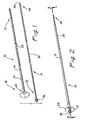
- a ureteral access sheath is illustrated in Figure 1 and designated generally by the reference numeral 10.
- the sheath 10 is illustrated in combination with a separate, but associated, dilator or obturator 12.
- the sheath 10 has the general configuration of an elongate tube 14 having an axis 16 which extends between a proximal end 18 and a distal end 21.
- a handle 23 is disposed at the proximal end 18 of the tube 14 and provides access into a working channel 25 of the tube 14.
- the obturator 12 will typically have the configuration of an elongate rod 30 extending between a proximal end 32 and a distal end 34.
- a knob 36 is disposed at the proximal end 32 and a tapered tip 38 is formed at the distal end 34.
- the obturator 12 is adapted to be inserted into the working channel 25 of the sheath 10 with the knob 36 extending proximally of the sheath 10, and the distal end 34 extending distally of the sheath 10.
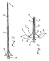
- This operative position of the obturator 12 within the sheath 10 is illustrated in the assembled view of Figure 2 .
- An axial cross-section view of the assembled combination is illustrated in Figure 3 where the rod 30 of the obturator 12 is more clearly shown within the working channel 25 of the sheath 10.
- the releasable lock (not shown) can be provided to removably attach the obturator 12 to the sheath 10.
- the obturator 12 and sheath 10 can then be passed as a single unit over the guidewire. This arrangement precludes inadvertent advancement of the sheath 10 in front of the obturator 12, which could greatly impede proper passage of the sheath and potentially the ureter.
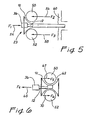
- the handle 23 associated with the sheath 10 is illustrated in the enlarged, axial cross-section view of Figure 4 . From this view it can be seen that the handle 23 has the general configuration of the bell of a horn.
- the handle 23 has a distally-facing surface 41 on the outside of the handle 23, and a proximally-facing surface 43 on the inside of the handle 23. Both of these surfaces 41 and 43 in the preferred embodiment are continuous and have a generally conical configuration.
- the distally-facing surface 41 is generally concave
- the proximally-facing surface 43 is generally convex.
- the handle 23 can be provided with two small holes 45, 46 for passage of sutures 47 and 48, respectively.
- the sutures 47, 48 can be clamped with hemostats (not shown) to the surgical drapes, thereby preventing distal migration of the sheath and loss of ureteral access.
- hemostats not shown
- proximally-facing surface 43 One of the purposes of the proximally-facing surface 43 is to funnel the obturator 12 and other surgical instrumentation into the working channel 25 of the sheath 10. With the generally conical configuration, this proximally-facing surface functions as a funnel with a radius which decreases with progressive distal positions along the axis 16. Thus, as the instrumentation is moved distally, the proximally-facing surface 43 guides the instrument along a decreasingly decreasing radius into the working channel 25 of the sheath 10. Providing the surface 43 with a generally convex configuration further facilitates this funneling feature of the invention. When the surface 43 is convex, its radius decreases at a decreasing rate with progressively equal distal positions along the axis 16.
- the distally-facing surface 41 is intended to facilitate engagement of the sheath 10 by a user's hand held in its most natural state.
- adjacent fingers 50 and 52 of the user's hands are illustrated schematically by the circles 50 and 52. In the natural state, the palm of the user's hands would be facing the user in the proximal direction, to the left in Figure 5 .
- the sheath 10 is adapted to be operatively positioned between the fingers 50 and 52 with the handle 23 positioned so that the distally-facing surface 41 is in juxtaposition to the fingers 50 and 52. This fit is facilitated by forming the surface 41 with a size and configuration generally similar to the fingers 50 and 52, as illustrated in Figure 5 .
- the distally-facing surface 41 having a generally conical configuration, it has a radius which decreases with progressive distal positions along the axis 16.
- the radius of the surface 41 decreases at a decreasing rate with progressively equal distal positions along the axis 16.
- FIG. 5 is particularly adapted to facilitate insertion of a surgical instrument, such as the obturator 12, it will be appreciated that removal of the instrument also creates withdrawal forces on the sheath 10.
- a handle 61 is similar to the handle 23, except that the outer, distally-facing surface 43 is curved distally outwardly to form a proximally-facing outer surface 63.
- the two surfaces 41 and 63 form a continuous surface which defines an annular recess sized and configured to receive the fingers 50 and 52.
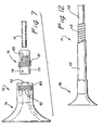
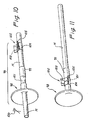
- Figures 7-9 illustrated a further embodiment involving a handle, such as the handles 23 or 61, which is movable relative to the tube 14 of the sheath 10.
- This embodiment is particularly desirable as it permits the tube 14 to be cut in situ, at the operative site, to a preferred length. With a sheath of this type, only a single access device need be present at the operative site. Multiple sheaths having different lengths are not required to be present in order to have a sheath of the desired length.
- this embodiment of the sheath 10 includes the tube 14 which is slidingly engageable by a handle assembly 72 that includes a sleeve 74 and a funnel 76.
- the sleeve 74 is formed as a cylinder 77 having an interior bore 78 and external threads 81.
- An elastomeric element 83 is disposed within the bore 78 and is provided with an axial lumen 84 appropriately sized to receive the tube 14.
- the funnel 76 is formed similar to the handle 23, but includes two concentric cylinders 85 and 87 which extend distally.
- the outer cylinder 85 is provided with interior threads 90, which are sized to receive the external threads 81 of the sleeve 74.
- the inner cylinder 87 of the funnel 76 is provided with an outer diameter less than the inner diameter of the bore 78. This inner cylinder 87 extends to a distal surface 92.
- the funnel 76 is moved axially over the sleeve 74 and the internal threads 90 are screwed onto the external threads 81. Further rotation of the funnel 76 relative to the sleeve 74, causes the distal surface 92 of the inner cylinder 87 to axially compress the elastomeric element 83. This compression causes the element 83 to expand inwardly decreasing the diameter of its lumen 84 and thereby increasing the frictional engagement of the handle assembly 72 relative to the tube 14.
- the tube 14 can be cut to a predetermined length, either before or after mounting the handle assembly 72 on the tube 14. Axial movement of the handle assembly 72 to a desired proximal location on the tube 14 provides the sheath 10 with the desired length. Operation of the handle 72 in the manner previously discussed will fix the assembly 72 on the tube 14 at this desired location.
- a movable handle assembly 96 includes a funnel 98 similar to the handle 23. It also includes a cylinder 99 which extends distally within portions 101 which have a reduced diameter.
- a separate finger clamp 102 includes a cylinder 104 which has a diameter which is dependent upon operation of finger tabs 103 and 105. When these tabs 103 and 105 are compressed, the cylinder 104 has a relatively large diameter. When the tabs 103 and 105 are not compressed, the cylinder 104 is biased toward a reduced diameter.
- This finger clamp 102 is intended to be operatively disposed over the thin portions 101 of the cylinder 99, as illustrated in Figure 11 .
- the entire handle assembly 96 can be moved along the tube 14 by compressing the finger tabs 103 and 105 of the clamp 102.
- the tube 14 can then be cut, for example, with scissors 106, to any desired length. Compressing the finger tabs 103 and 105 will permit the handle assembly 96 to be moved to a distal position, as illustrated in Figure 11 , where the tabs 103 and 105 can be released to compress the thin portions 101 and maintain the handle assembly 96 in a fixed relationship with the tube 14.
- the tube 14 is formed with an inner plastic body 110, surrounded by a metal spring coil 112, which is further covered by an outer body 114.
- This particular embodiment of the tube 14 provides a high degree of kink resistance and can be used with any of the handle assemblies previously discussed.
- the inner body 110 provides a smooth surface within the sheath 10, which facilitates passage of instrumentation.
- the spring coil 112 adds kink resistance to the tube 14, while the outer body 114 provides a suitable covering for the coils of the spring 112.
Landscapes
- Health & Medical Sciences (AREA)
- Life Sciences & Earth Sciences (AREA)
- Biomedical Technology (AREA)
- Heart & Thoracic Surgery (AREA)
- Biophysics (AREA)
- Pulmonology (AREA)
- Engineering & Computer Science (AREA)
- Anesthesiology (AREA)
- Veterinary Medicine (AREA)
- Public Health (AREA)
- Hematology (AREA)
- Animal Behavior & Ethology (AREA)
- General Health & Medical Sciences (AREA)
- Urology & Nephrology (AREA)
- Epidemiology (AREA)
- Surgical Instruments (AREA)
- Endoscopes (AREA)
- Media Introduction/Drainage Providing Device (AREA)
Claims (16)
- Hülse (10) als Zugang zum Ureter, die zum Einschieben in eine Harnröhre mit einem ersten Durchmesser angepasst ist, umfassend:eine längliche Röhre (14) mit einem zweiten Durchmesser und einem Lumen, das sich zwischen einem proximalen Ende (18) und einem distalen Ende (21) erstreckt;einen ersten Griff (23), der am proximalen Ende der Röhre (14) angeordnet ist;wobei sich Teile des ersten Griffs (23) von der länglichen Röhre (14) radial nach außen gerichtet erstrecken, um den ersten Griff (23) mit einem dritten Durchmesser zu versehen, der größer als der erste Durchmesser der Harnröhre ist, wobei die Griffteile durch eine erste Oberfläche (41), die generell dem distalen Ende zugewandt ist, und eine zweite Oberfläche (43), die generell dem proximalen Ende zugewandt ist, definiert sind und die zweite Oberfläche einen Trichter (76) bildet, der in das Lumen der Röhre (14) einleitet; wodurchdie Griffteile distale Wanderung des proximalen Endes der Röhre (14) in die Urethra inhibieren, dadurch gekennzeichnet, dass die längliche Röhre (14) eine Schraubenfeder (112) einschließt.
- Zugangshülse nach Anspruch 1, wobei die Hülse zur Benutzung durch eine Person angepasst ist, die ein Paar nebeneinanderliegender Finger hat und, wobei:die erste Oberfläche (41) kontinuierlich ist und sowohl bemessen als auch konfiguriert ist, die nebeneinanderliegenden Finger des Benutzers aufzunehmen.
- Zugangshülse nach einem beliebigen vorhergehenden Anspruch, wobei die zweite Oberfläche (43) konvex ist.
- Zugangshülse nach einem beliebigen vorhergehenden Anspruch, wobei die erste Oberfläche (41) konkav ist.
- Zugangshülse nach einem beliebigen vorhergehenden Anspruch, wobei sich die zweite Oberfläche (43) abnehmend radial nach innen gerichtet mit progressiven gleichen distalen Positionen entlang der Röhre (14) erstreckt.
- Zugangshülse nach einem beliebigen vorhergehenden Anspruch, wobei sich die erste Oberfläche (41) abnehmend radial nach innen gerichtet mit progressiven gleichen distalen Positionen entlang der Röhre (14) erstreckt.
- Zugangshülse nach einem beliebigen vorhergehenden Anspruch, die weiter einen zweiten Griff (61) einschließt, der distal des ersten Griffs (23) angeordnet ist, wobei der zweite Griff eine dritte Oberfläche (63) einschließt, die generell dem proximalen Ende zugewandt ist,
wobei die erste Oberfläche (41) und die dritte Oberfläche (63) konkav, kontinuierlich und sowohl bemessen als auch konfiguriert sind, die nebeneinanderliegenden Finger des Benutzers aufzunehmen,
wobei die erste Oberfläche (41) kontinuierlich mit der dritten Oberfläche (63) ist, um eine ringförmige Vertiefung zu definieren. - Hülse als Zugang zum Ureter nach einem beliebigen vorhergehenden Anspruch,
wobei die längliche Röhre (14) einen Innenkörper (11), der von der Schraubenfeder (112) umgeben ist und einen Außenkörper (114) umfasst, der die Schraubenfeder abdeckt. - Hülse als Zugang zum Ureter nach einem beliebigen vorhergehenden Anspruch, wobei die Schraubenfeder (112) der Röhre (14) Knickbeständigkeit verleiht.
- Hülse als Zugang zum Ureter nach einem beliebigen vorhergehenden Anspruch, die weiter einen Obturator (12) einschließt, der eine längliche Stange (30) umfasst, die sich zwischen einem proximalen Ende (32) und einem distalen Ende (34) erstreckt, die durch das Lumen der länglichen Röhre (14) einschiebbar und daraus entfernbar ist.
- Hülse als Zugang zum Ureter nach Anspruch 10, wobei der Obturator (12) weiter einen lösbaren Mechanismus einschließt, der am proximalen Ende (32) der länglichen Stange (30) angeordnet ist, die entfernbar am ersten Griff (23) befestigt ist.
- Hülse als Zugang zum Ureter nach Anspruch 11, wobei die Befestigung des Obturators (12) an der Hülse unbeabsichtigten Vorschub der Hülse vor dem Obturator (12) ausschließt.
- Hülse als Zugang zum Ureter nach Anspruch 10, wobei der Obturator (12) einen Knopf (36), der am proximalen Ende (32) des Obturators (12) angeordnet ist und eine konische Spitze (38) am distalen Ende des Obturators (12) einschließt.
- Hülse als Zugang zum Ureter nach Anspruch 13, wobei sich der Knopf (36) des Obturators (12) proximal am proximalen Ende (18) der länglichen Röhre (14) vorbei erstreckt und sich das distale Ende (34) des Obturators (12) distal am distalen Ende (21) der länglichen Röhre (14) vorbei erstreckt, wenn dieser innenseitig des Lumens der länglichen Röhre (14) eingeschoben ist.
- Hülse als Zugang zum Ureter nach einem beliebigen der Ansprüche, die weiter zumindest ein Loch (45, 46) zum Durchgang zumindest einer Naht einschließt, wobei das Loch im Wesentlichen senkrecht zur Achse (16) der länglichen Röhre (14) positioniert ist.
- Hülse als Zugang zum Ureter nach einem beliebigen der Ansprüche, wobei die zweite Oberfläche mit einer abnehmenden Rate mit progressiv gleichen Teilen entlang der Achse radial abnimmt.
Priority Applications (3)
| Application Number | Priority Date | Filing Date | Title |
|---|---|---|---|
| EP12190918.8A EP2617455B1 (de) | 1999-04-30 | 2000-04-26 | Ureteraler Zugriffsschafft |
| EP12190914.7A EP2617454B1 (de) | 1999-04-30 | 2000-04-26 | Ureteraler Zugriffsschafft |
| EP11170611.5A EP2368594B1 (de) | 1999-04-30 | 2000-04-26 | Ureteraler Zugriffsschafft |
Applications Claiming Priority (3)
| Application Number | Priority Date | Filing Date | Title |
|---|---|---|---|
| US303485 | 1999-04-30 | ||
| US09/303,485 US6471684B2 (en) | 1999-04-30 | 1999-04-30 | Ureteral access sheath |
| PCT/US2000/011219 WO2000066212A1 (en) | 1999-04-30 | 2000-04-26 | Ureteral access sheath |
Related Child Applications (4)
| Application Number | Title | Priority Date | Filing Date |
|---|---|---|---|
| EP12190914.7A Division EP2617454B1 (de) | 1999-04-30 | 2000-04-26 | Ureteraler Zugriffsschafft |
| EP12190918.8A Division EP2617455B1 (de) | 1999-04-30 | 2000-04-26 | Ureteraler Zugriffsschafft |
| EP11170611.5A Division EP2368594B1 (de) | 1999-04-30 | 2000-04-26 | Ureteraler Zugriffsschafft |
| EP11170611.5 Division-Into | 2011-06-20 |
Publications (3)
| Publication Number | Publication Date |
|---|---|
| EP1173248A1 EP1173248A1 (de) | 2002-01-23 |
| EP1173248A4 EP1173248A4 (de) | 2007-05-02 |
| EP1173248B1 true EP1173248B1 (de) | 2011-10-05 |
Family
ID=23172338
Family Applications (4)
| Application Number | Title | Priority Date | Filing Date |
|---|---|---|---|
| EP11170611.5A Expired - Lifetime EP2368594B1 (de) | 1999-04-30 | 2000-04-26 | Ureteraler Zugriffsschafft |
| EP12190918.8A Expired - Lifetime EP2617455B1 (de) | 1999-04-30 | 2000-04-26 | Ureteraler Zugriffsschafft |
| EP00931958A Expired - Lifetime EP1173248B1 (de) | 1999-04-30 | 2000-04-26 | Hülse als zugang zum urether |
| EP12190914.7A Expired - Lifetime EP2617454B1 (de) | 1999-04-30 | 2000-04-26 | Ureteraler Zugriffsschafft |
Family Applications Before (2)
| Application Number | Title | Priority Date | Filing Date |
|---|---|---|---|
| EP11170611.5A Expired - Lifetime EP2368594B1 (de) | 1999-04-30 | 2000-04-26 | Ureteraler Zugriffsschafft |
| EP12190918.8A Expired - Lifetime EP2617455B1 (de) | 1999-04-30 | 2000-04-26 | Ureteraler Zugriffsschafft |
Family Applications After (1)
| Application Number | Title | Priority Date | Filing Date |
|---|---|---|---|
| EP12190914.7A Expired - Lifetime EP2617454B1 (de) | 1999-04-30 | 2000-04-26 | Ureteraler Zugriffsschafft |
Country Status (5)
| Country | Link |
|---|---|
| US (2) | US6471684B2 (de) |
| EP (4) | EP2368594B1 (de) |
| JP (2) | JP2002542902A (de) |
| CA (1) | CA2368769C (de) |
| WO (1) | WO2000066212A1 (de) |
Cited By (3)
| Publication number | Priority date | Publication date | Assignee | Title |
|---|---|---|---|---|
| DE102012020693B3 (de) * | 2012-10-22 | 2013-10-17 | Urotech Medizinische Technologie Gmbh | Medizinische Vorrichtung zum Einführen in eine Körperöffnung oder -höhle eines Individuums |
| DE202012010064U1 (de) | 2012-10-22 | 2014-01-24 | Urotech Medizinische Technologie Gmbh | Medizinische Vorrichtung zum Einführen in eine Körperöffnung oder -höhle eines Individuums |
| WO2014063675A1 (de) | 2012-10-22 | 2014-05-01 | Urotech Medizinische Technologie Gmbh | Medizinische vorrichtung zum einführen in eine körperöffnung oder -höhle eines individuums |
Families Citing this family (77)
| Publication number | Priority date | Publication date | Assignee | Title |
|---|---|---|---|---|
| DE10014857B4 (de) * | 2000-01-05 | 2005-12-29 | Manfred Sauer | Vorrichtung zum Einführen eines Katheters in die Harnröhre |
| ATE318638T1 (de) * | 2002-07-11 | 2006-03-15 | Nucletron Bv | Harnröhrensonde |
| US6907884B2 (en) | 2002-09-30 | 2005-06-21 | Depay Acromed, Inc. | Method of straddling an intraosseous nerve |
| US8361067B2 (en) | 2002-09-30 | 2013-01-29 | Relievant Medsystems, Inc. | Methods of therapeutically heating a vertebral body to treat back pain |
| US7258690B2 (en) | 2003-03-28 | 2007-08-21 | Relievant Medsystems, Inc. | Windowed thermal ablation probe |
| US7005026B2 (en) | 2002-11-15 | 2006-02-28 | Applied Medical Resources Corporation | Kink-resistant access sheath and method of making same |
| US20040116904A1 (en) * | 2002-12-05 | 2004-06-17 | Manoj Monga | Percutaneous plug |
| US7655021B2 (en) * | 2003-03-10 | 2010-02-02 | Boston Scientific Scimed, Inc. | Dilator with expandable member |
| US7654989B2 (en) * | 2003-04-08 | 2010-02-02 | C. R. Bard, Inc. | Ureteral access sheath |
| US20050055303A1 (en) * | 2003-09-08 | 2005-03-10 | General Hydrogen Corp. | Method for incentivizing customers to confirm advance purchase orders |
| US9241735B2 (en) | 2003-12-05 | 2016-01-26 | Onset Medical Corporation | Expandable percutaneous sheath |
| US7780692B2 (en) | 2003-12-05 | 2010-08-24 | Onset Medical Corporation | Expandable percutaneous sheath |
| US7699864B2 (en) * | 2004-03-18 | 2010-04-20 | Onset Medical Corporation | Expandable medical access device |
| AU2005231304A1 (en) * | 2004-03-30 | 2005-10-20 | Cook Urological Incorporated | Multiple lumen access sheath |
| US8535293B2 (en) | 2004-04-13 | 2013-09-17 | Gyrus Acmi, Inc. | Atraumatic ureteral access sheath |
| US8235968B2 (en) * | 2004-04-13 | 2012-08-07 | Gyrus Acmi, Inc. | Atraumatic ureteral access sheath |
| US8517921B2 (en) * | 2004-04-16 | 2013-08-27 | Gyrus Acmi, Inc. | Endoscopic instrument having reduced diameter flexible shaft |
| US20060135981A1 (en) | 2004-09-09 | 2006-06-22 | Jay Lenker | Expandable transluminal sheath |
| US7892203B2 (en) | 2004-09-09 | 2011-02-22 | Onset Medical Corporation | Expandable transluminal sheath |
| US20060135962A1 (en) | 2004-09-09 | 2006-06-22 | Kick George F | Expandable trans-septal sheath |
| GB0501750D0 (en) * | 2005-01-27 | 2005-03-02 | Univ College London Hospitals | Drain tube assembly for draining a body cavity |
| US20060253104A1 (en) * | 2005-04-20 | 2006-11-09 | Boston Scientific Scimed, Inc. | Access and drainage devices and methods of use thereof |
| US8092481B2 (en) | 2005-06-03 | 2012-01-10 | Onset Medical Corporation | Expandable percutaneous sheath |
| WO2007022223A2 (en) * | 2005-08-17 | 2007-02-22 | Colorado Catheter Company, Inc. | Catheterization assembly |
| US20070050006A1 (en) * | 2005-08-31 | 2007-03-01 | Cook Ireland Limited | Coaxial dilatation method for stent implantation |
| US7803130B2 (en) | 2006-01-09 | 2010-09-28 | Vance Products Inc. | Deflectable tip access sheath |
| US8317775B2 (en) * | 2006-03-10 | 2012-11-27 | Adapta Medical, Inc. | Urinary catheterization assembly with vented sheath |
| US7662146B2 (en) * | 2006-03-10 | 2010-02-16 | Colorado Catheter Company, Inc. | Indwelling urinary catheterization assembly |
| US7601158B2 (en) * | 2006-07-17 | 2009-10-13 | Colorado Catheter Company, Inc. | Devices for handling catheter assembly |
| US8491552B2 (en) | 2006-09-25 | 2013-07-23 | Adapta Medical, Inc. | External catheter with antiseptic agent |
| US20080097411A1 (en) * | 2006-09-25 | 2008-04-24 | Jamie Glen House | Catheter assemblies having sized sheaths |
| US7918831B2 (en) * | 2006-10-12 | 2011-04-05 | Colorado Catheter Company, Inc. | Catheter assembly having protective sheath |
| US7601142B2 (en) * | 2006-10-12 | 2009-10-13 | Colorado Catheter Company, Inc. | Devices for connecting catheter assembly to collection receptacle |
| US8888747B2 (en) | 2006-10-12 | 2014-11-18 | Adapta Medical, Inc. | Catheter assembly with vents |
| US20080146985A1 (en) * | 2006-12-14 | 2008-06-19 | Jamie Glen House | Body treatment devices and methods |
| US8337518B2 (en) | 2006-12-20 | 2012-12-25 | Onset Medical Corporation | Expandable trans-septal sheath |
| US7938807B2 (en) | 2007-01-12 | 2011-05-10 | Adapta Medical, Inc. | Devices and methods for securing catheter assemblies |
| US8177765B2 (en) | 2007-01-12 | 2012-05-15 | Adapta Medical, Inc. | Collection devices for catheter assemblies |
| WO2008103644A1 (en) * | 2007-02-21 | 2008-08-28 | Colorado Catheter Company, Inc. | Devices for connecting catheter assembly to collection receptacle |
| US20090318894A1 (en) * | 2008-06-24 | 2009-12-24 | Mathieu Lafitte | Method for positioning an access sheath and a security guide, a catheter for positioning an access sheath and a catheter-access sheath assembly |
| US20090281369A1 (en) * | 2008-05-09 | 2009-11-12 | Coloplast A/S | Urethral Spring, Implantation Tools, and Method of Treating Incontinence |
| EP2339972B1 (de) | 2008-09-26 | 2018-04-11 | Relievant Medsystems, Inc. | Systeme zur navigation eines instruments durch knochen |
| US10028753B2 (en) | 2008-09-26 | 2018-07-24 | Relievant Medsystems, Inc. | Spine treatment kits |
| KR100898932B1 (ko) | 2008-11-07 | 2009-05-21 | 인제대학교 산학협력단 | 전방요도 지지용 보조기구 |
| US7951110B2 (en) * | 2008-11-10 | 2011-05-31 | Onset Medical Corporation | Expandable spinal sheath and method of use |
| US8758231B2 (en) | 2009-05-14 | 2014-06-24 | Cook Medical Technologies Llc | Access sheath with active deflection |
| US8512232B2 (en) * | 2009-09-08 | 2013-08-20 | Gyrus Acmi, Inc. | Endoscopic illumination system, assembly and methods for staged illumination of different target areas |
| WO2011150111A1 (en) | 2010-05-28 | 2011-12-01 | Gyrus Acmi, Inc. | Continuous flow endoscope system |
| US10751206B2 (en) | 2010-06-26 | 2020-08-25 | Scott M. Epstein | Catheter or stent delivery system |
| US20110319902A1 (en) | 2010-06-26 | 2011-12-29 | Scott Epstein | Catheter delivery system |
| US9345853B2 (en) * | 2010-12-10 | 2016-05-24 | Teknor Apex Company | Tube assembly and method for making the assembly |
| US10390877B2 (en) | 2011-12-30 | 2019-08-27 | Relievant Medsystems, Inc. | Systems and methods for treating back pain |
| CN102715922A (zh) * | 2012-06-27 | 2012-10-10 | 上海英诺伟微创医疗器械有限公司 | 一种腹腔镜手术穿刺器的导引器 |
| US10588691B2 (en) | 2012-09-12 | 2020-03-17 | Relievant Medsystems, Inc. | Radiofrequency ablation of tissue within a vertebral body |
| EP2914186B1 (de) | 2012-11-05 | 2019-03-13 | Relievant Medsystems, Inc. | Systeme zur erzeugung von kurven durch knochen und modulationsnerven innerhalb von knochen |
| LT2916901T (lt) | 2012-11-12 | 2020-10-12 | Hollister Incorporated | Pertraukiamas kateterio mazgas |
| WO2014077886A1 (en) | 2012-11-14 | 2014-05-22 | Hollister Incorporated | Disposable catheter with selectively degradable inner core |
| US8956340B2 (en) * | 2012-12-13 | 2015-02-17 | University Of South Florida | Urethral catheter assembly with a guide wire |
| EP2777745B1 (de) | 2013-03-15 | 2018-05-30 | Coloplast A/S | Zugangshülle |
| US9724151B2 (en) | 2013-08-08 | 2017-08-08 | Relievant Medsystems, Inc. | Modulating nerves within bone using bone fasteners |
| AU2014346748B2 (en) | 2013-11-08 | 2018-05-10 | Hollister Incorporated | Oleophilic lubricated catheters |
| AU2014362360B2 (en) | 2013-12-12 | 2020-01-02 | Hollister Incorporated | Flushable catheters |
| DK3079749T3 (da) | 2013-12-12 | 2019-12-16 | Hollister Inc | Udskyllelige katetre |
| AU2014363933B2 (en) | 2013-12-12 | 2019-10-10 | Hollister Incorporated | Flushable disintegration catheter |
| ES2802950T3 (es) | 2013-12-12 | 2021-01-22 | Hollister Inc | Catéteres desechables por el inodoro |
| US10118019B2 (en) | 2014-01-09 | 2018-11-06 | Hollister Incorporated | Catheter cartridge assemblies and methods of using the same for intermittent catheterization |
| EP3092023B1 (de) | 2014-01-09 | 2019-11-13 | Hollister Incorporated | Katheteranordnungen mit einer gleitfähigen schutzhülse |
| US9320508B2 (en) | 2014-02-27 | 2016-04-26 | Gyrus Acmi, Inc. | Expandable medical access sheath |
| US10828051B2 (en) | 2014-07-28 | 2020-11-10 | Shaw P. Wan | Suction evacuation device |
| CN104147683A (zh) * | 2014-08-28 | 2014-11-19 | 河南科技大学第一附属医院 | 一种用于留置导尿管的尿道探子 |
| US11185613B2 (en) | 2015-06-17 | 2021-11-30 | Hollister Incorporated | Selectively water disintegrable materials and catheters made of such materials |
| KR200485261Y1 (ko) * | 2016-10-17 | 2017-12-13 | 주식회사 대지약품 | 무 바늘 주사기 |
| USD948716S1 (en) | 2019-07-30 | 2022-04-12 | Stinger Endoscopy LLC | Endoscope |
| WO2021050767A1 (en) | 2019-09-12 | 2021-03-18 | Relievant Medsystems, Inc. | Systems and methods for tissue modulation |
| US12082876B1 (en) | 2020-09-28 | 2024-09-10 | Relievant Medsystems, Inc. | Introducer drill |
| JP2024505335A (ja) | 2020-12-22 | 2024-02-06 | リリーバント メドシステムズ、インコーポレイテッド | 脊椎神経調節の候補の予測 |
| US11452849B2 (en) * | 2021-01-22 | 2022-09-27 | MicroLinerTechnologies, Inc. | Systems and devices for atraumatic catheter insertion along a guidewire |
Family Cites Families (39)
| Publication number | Priority date | Publication date | Assignee | Title |
|---|---|---|---|---|
| US1538678A (en) * | 1923-02-24 | 1925-05-19 | Joseph S Blinn | Suppository injector |
| US1538679A (en) * | 1923-05-08 | 1925-05-19 | Blinn Joseph Sylvester | Suppository injector |
| US2747574A (en) * | 1954-09-29 | 1956-05-29 | Lorenzo Joseph P De | Disposable package and applicator for suppositories |
| US3154074A (en) * | 1962-10-23 | 1964-10-27 | Lehn & Fink Products Corp | Internal medicament applicator |
| DE1295140B (de) * | 1963-12-14 | 1969-05-14 | Ernst Kratz Fa | Verfahren zum Befestigen einer Kanuele in einem Kunststoff-Ansatz und nach diesem Verfahren hergestellte Injektionsnadel |
| US3332424A (en) * | 1965-02-03 | 1967-07-25 | Discon Corp | Extroversive catheter |
| US3421509A (en) * | 1965-12-17 | 1969-01-14 | John M Fiore | Urethral catheter |
| DE1491743A1 (de) * | 1966-07-13 | 1969-06-26 | Georg A Henke Gmbh | Injektionsnadel und Verfahren zu ihrer Herstellung |
| US3592197A (en) * | 1969-03-24 | 1971-07-13 | Milton J Cohen | Catheter |
| US3720210A (en) * | 1971-03-03 | 1973-03-13 | Baxter Laboratories Inc | Indwelling catheter device |
| US4068659A (en) * | 1976-07-12 | 1978-01-17 | Deseret Pharmaceutical Co., Inc. | Catheter placement assembly |
| US4354495A (en) * | 1980-10-30 | 1982-10-19 | Sherwood Medical Industries Inc. | Method of connecting plastic tube to a plastic part |
| US4636199A (en) * | 1984-07-09 | 1987-01-13 | Victor Lyle D | Device for inserting a catheter within the intercostal space |
| US5041083A (en) * | 1987-06-25 | 1991-08-20 | Terumo Kabushiki Kaisha | Multi-luminal catheter, multi-luminal catheter assembly |
| USD318733S (en) | 1988-03-24 | 1991-07-30 | Quinton Instrument Company | Pull-apart sheath introducer for percutaneous catheter introduction |
| DE3812754C1 (de) | 1988-04-16 | 1989-04-27 | Rudolf Schoen | |
| US4961477A (en) * | 1988-06-08 | 1990-10-09 | Sweeney John F | Wheel chair transporter |
| US4932413A (en) * | 1989-03-13 | 1990-06-12 | Schneider (Usa), Inc. | Guidewire exchange catheter |
| US4942669A (en) * | 1989-10-03 | 1990-07-24 | Schnedl Edwin F | Dipstick locator and wiper construction for automobiles |
| US5242391A (en) * | 1990-04-25 | 1993-09-07 | Alza Corporation | Urethral insert for treatment of erectile dysfunction |
| US5154005A (en) * | 1990-07-24 | 1992-10-13 | Lalevee Sr Russell R | Dip stick guide, combination dip stick and dip stick holder |
| US5112308A (en) * | 1990-10-03 | 1992-05-12 | Cook Incorporated | Medical device for and a method of endoscopic surgery |
| USD335710S (en) | 1990-12-21 | 1993-05-18 | Circon Corporation | Mini-rigid ureteroscope |
| US5513660A (en) * | 1990-12-31 | 1996-05-07 | Uromed Corporation | Expandable urethral plug |
| US5531717A (en) * | 1993-12-12 | 1996-07-02 | Rtc, Inc. | Non-contaminating probe and methods of making and using same |
| US5131380A (en) | 1991-06-13 | 1992-07-21 | Heller Richard M | Softwall medical tube with fiberoptic light conductor therein and method of use |
| US5344413A (en) * | 1991-06-28 | 1994-09-06 | C. R. Bard, Inc. | Catheter having a tip connector for rapid catheter exchanges |
| US5380304A (en) * | 1991-08-07 | 1995-01-10 | Cook Incorporated | Flexible, kink-resistant, introducer sheath and method of manufacture |
| US5407441A (en) * | 1992-06-04 | 1995-04-18 | Greenbaum; Scott | Ophthalmologic cannula |
| US5372592A (en) * | 1992-06-22 | 1994-12-13 | C. R. Bard, Inc. | Method and device for preparing catheters prior to use |
| FR2701648B1 (fr) * | 1993-02-19 | 1995-03-31 | Marian Devonec | Prothèse destinée au traitement d'une lumière ou voie naturelle, notamment prothèse endo-uréthrale. |
| US5431676A (en) * | 1993-03-05 | 1995-07-11 | Innerdyne Medical, Inc. | Trocar system having expandable port |
| IT1273015B (it) * | 1994-07-27 | 1997-07-01 | Piefrancesco Pavoni | "dispositivo per il rilevamento termometrico invasivo e per l'introduzione di un medicamento per applicazioni di ipertermia superficiale e profonda". |
| US5569159A (en) | 1994-12-16 | 1996-10-29 | Anderson; Keven C. | Endoscopic sleeve |
| US5620408A (en) | 1995-04-14 | 1997-04-15 | Vennes; Jack A. | Endoscopic over-tube |
| US5891112A (en) * | 1995-04-28 | 1999-04-06 | Target Therapeutics, Inc. | High performance superelastic alloy braid reinforced catheter |
| AUPN976296A0 (en) * | 1996-05-09 | 1996-05-30 | Cryptych Pty Ltd | Ear irrigation device |
| US5718678A (en) * | 1996-06-26 | 1998-02-17 | Medical Components, Inc. | Multi-lumen coaxial catheter and method for making same |
| US6872198B1 (en) * | 2001-01-24 | 2005-03-29 | Arrow International, Inc. | Double-y-shaped multi-lumen catheter with selectively attachable hubs |
-
1999
- 1999-04-30 US US09/303,485 patent/US6471684B2/en not_active Expired - Lifetime
-
2000
- 2000-04-26 CA CA002368769A patent/CA2368769C/en not_active Expired - Lifetime
- 2000-04-26 EP EP11170611.5A patent/EP2368594B1/de not_active Expired - Lifetime
- 2000-04-26 WO PCT/US2000/011219 patent/WO2000066212A1/en active Application Filing
- 2000-04-26 EP EP12190918.8A patent/EP2617455B1/de not_active Expired - Lifetime
- 2000-04-26 EP EP00931958A patent/EP1173248B1/de not_active Expired - Lifetime
- 2000-04-26 EP EP12190914.7A patent/EP2617454B1/de not_active Expired - Lifetime
- 2000-04-26 JP JP2000615093A patent/JP2002542902A/ja active Pending
-
2001
- 2001-06-13 US US09/882,630 patent/US7135015B2/en not_active Expired - Lifetime
-
2008
- 2008-08-25 JP JP2008215704A patent/JP2009034522A/ja not_active Abandoned
Cited By (4)
| Publication number | Priority date | Publication date | Assignee | Title |
|---|---|---|---|---|
| DE102012020693B3 (de) * | 2012-10-22 | 2013-10-17 | Urotech Medizinische Technologie Gmbh | Medizinische Vorrichtung zum Einführen in eine Körperöffnung oder -höhle eines Individuums |
| DE202012010064U1 (de) | 2012-10-22 | 2014-01-24 | Urotech Medizinische Technologie Gmbh | Medizinische Vorrichtung zum Einführen in eine Körperöffnung oder -höhle eines Individuums |
| WO2014063675A1 (de) | 2012-10-22 | 2014-05-01 | Urotech Medizinische Technologie Gmbh | Medizinische vorrichtung zum einführen in eine körperöffnung oder -höhle eines individuums |
| US9744334B2 (en) | 2012-10-22 | 2017-08-29 | Urotech Gmbh | Medical device for introducing into a bodily orifice or cavity of an individual |
Also Published As
| Publication number | Publication date |
|---|---|
| EP2368594A1 (de) | 2011-09-28 |
| US7135015B2 (en) | 2006-11-14 |
| EP2617455A3 (de) | 2013-08-28 |
| US20010027295A1 (en) | 2001-10-04 |
| JP2002542902A (ja) | 2002-12-17 |
| EP2617455A2 (de) | 2013-07-24 |
| EP2617455B1 (de) | 2015-07-29 |
| EP1173248A4 (de) | 2007-05-02 |
| CA2368769A1 (en) | 2000-11-09 |
| US6471684B2 (en) | 2002-10-29 |
| EP1173248A1 (de) | 2002-01-23 |
| EP2617454A2 (de) | 2013-07-24 |
| WO2000066212A1 (en) | 2000-11-09 |
| US20020038115A1 (en) | 2002-03-28 |
| EP2617454B1 (de) | 2014-06-11 |
| EP2368594B1 (de) | 2016-02-17 |
| JP2009034522A (ja) | 2009-02-19 |
| EP2617454A3 (de) | 2013-08-28 |
| CA2368769C (en) | 2008-09-30 |
Similar Documents
| Publication | Publication Date | Title |
|---|---|---|
| EP1173248B1 (de) | Hülse als zugang zum urether | |
| US8282622B2 (en) | Ureteral access sheath | |
| US5209741A (en) | Surgical access device having variable post-insertion cross-sectional geometry | |
| CA1223829A (en) | Sheath | |
| US6159198A (en) | Introducer system | |
| EP2346562B1 (de) | Medizinisches führungselement mit durchmesserübergang | |
| US5209735A (en) | External guide wire and enlargement means | |
| EP1641402B1 (de) | Handstück für eine medizinische vorrichtung, sowie medizinische vorrichtung mit einem solchen handstück | |
| US20130274783A1 (en) | Percutaneous renal access system | |
| JP3117089B2 (ja) | ニードルガイド | |
| EP1601405B1 (de) | Katheter mit begrenzter längsausdehnung | |
| GB2240926A (en) | An expansible cannula | |
| CA2122817A1 (en) | Surgical instrument stabilizer | |
| KR20070082046A (ko) | 의료 장치, 관 삽입 기구 및 상기 의료 장치를 갖는 관삽입 기구 | |
| US20020068911A1 (en) | Removable protective cannula for use in surgery | |
| JPH0749058B2 (ja) | 麻酔器具 | |
| EP1713536B1 (de) | Katheterführungsdraht | |
| US20040260205A1 (en) | Guidewire exit tool | |
| WO2004006989A2 (en) | Ureteral access sheath | |
| US5542930A (en) | Catheter assembly | |
| JPH07275188A (ja) | 経皮的に挿入される内視鏡 |
Legal Events
| Date | Code | Title | Description |
|---|---|---|---|
| PUAI | Public reference made under article 153(3) epc to a published international application that has entered the european phase |
Free format text: ORIGINAL CODE: 0009012 |
|
| 17P | Request for examination filed |
Effective date: 20011005 |
|
| AK | Designated contracting states |
Kind code of ref document: A1 Designated state(s): AT BE CH CY DE DK ES FI FR GB GR IE IT LI LU MC NL PT SE |
|
| RIN1 | Information on inventor provided before grant (corrected) |
Inventor name: DULAK, GARY, R. Inventor name: CLAYMAN, RALPH, V. |
|
| RAP1 | Party data changed (applicant data changed or rights of an application transferred) |
Owner name: APPLIED MEDICAL RESOURCES CORPORATION |
|
| RBV | Designated contracting states (corrected) |
Designated state(s): DE FR GB |
|
| A4 | Supplementary search report drawn up and despatched |
Effective date: 20070404 |
|
| 17Q | First examination report despatched |
Effective date: 20101130 |
|
| GRAP | Despatch of communication of intention to grant a patent |
Free format text: ORIGINAL CODE: EPIDOSNIGR1 |
|
| GRAS | Grant fee paid |
Free format text: ORIGINAL CODE: EPIDOSNIGR3 |
|
| GRAA | (expected) grant |
Free format text: ORIGINAL CODE: 0009210 |
|
| AK | Designated contracting states |
Kind code of ref document: B1 Designated state(s): DE FR GB |
|
| REG | Reference to a national code |
Ref country code: GB Ref legal event code: FG4D |
|
| REG | Reference to a national code |
Ref country code: DE Ref legal event code: R096 Ref document number: 60046512 Country of ref document: DE Effective date: 20111208 |
|
| PLBE | No opposition filed within time limit |
Free format text: ORIGINAL CODE: 0009261 |
|
| STAA | Information on the status of an ep patent application or granted ep patent |
Free format text: STATUS: NO OPPOSITION FILED WITHIN TIME LIMIT |
|
| 26N | No opposition filed |
Effective date: 20120706 |
|
| REG | Reference to a national code |
Ref country code: DE Ref legal event code: R097 Ref document number: 60046512 Country of ref document: DE Effective date: 20120706 |
|
| REG | Reference to a national code |
Ref country code: FR Ref legal event code: PLFP Year of fee payment: 17 |
|
| REG | Reference to a national code |
Ref country code: FR Ref legal event code: PLFP Year of fee payment: 18 |
|
| REG | Reference to a national code |
Ref country code: FR Ref legal event code: PLFP Year of fee payment: 19 |
|
| PGFP | Annual fee paid to national office [announced via postgrant information from national office to epo] |
Ref country code: DE Payment date: 20190429 Year of fee payment: 20 |
|
| PGFP | Annual fee paid to national office [announced via postgrant information from national office to epo] |
Ref country code: FR Payment date: 20190425 Year of fee payment: 20 |
|
| PGFP | Annual fee paid to national office [announced via postgrant information from national office to epo] |
Ref country code: GB Payment date: 20190429 Year of fee payment: 20 |
|
| REG | Reference to a national code |
Ref country code: DE Ref legal event code: R071 Ref document number: 60046512 Country of ref document: DE |
|
| REG | Reference to a national code |
Ref country code: GB Ref legal event code: PE20 Expiry date: 20200425 |
|
| PG25 | Lapsed in a contracting state [announced via postgrant information from national office to epo] |
Ref country code: GB Free format text: LAPSE BECAUSE OF EXPIRATION OF PROTECTION Effective date: 20200425 |
|
| P01 | Opt-out of the competence of the unified patent court (upc) registered |
Effective date: 20230525 |