EP1170237A2 - Verfahren zur Ausrichtung bogenförmigen Materials - Google Patents
Verfahren zur Ausrichtung bogenförmigen Materials Download PDFInfo
- Publication number
- EP1170237A2 EP1170237A2 EP01110274A EP01110274A EP1170237A2 EP 1170237 A2 EP1170237 A2 EP 1170237A2 EP 01110274 A EP01110274 A EP 01110274A EP 01110274 A EP01110274 A EP 01110274A EP 1170237 A2 EP1170237 A2 EP 1170237A2
- Authority
- EP
- European Patent Office
- Prior art keywords
- sheet material
- central axis
- aligned
- turned around
- printing
- Prior art date
- Legal status (The legal status is an assumption and is not a legal conclusion. Google has not performed a legal analysis and makes no representation as to the accuracy of the status listed.)
- Granted
Links
Images

Classifications
-
- B—PERFORMING OPERATIONS; TRANSPORTING
- B65—CONVEYING; PACKING; STORING; HANDLING THIN OR FILAMENTARY MATERIAL
- B65H—HANDLING THIN OR FILAMENTARY MATERIAL, e.g. SHEETS, WEBS, CABLES
- B65H9/00—Registering, e.g. orientating, articles; Devices therefor
- B65H9/002—Registering, e.g. orientating, articles; Devices therefor changing orientation of sheet by only controlling movement of the forwarding means, i.e. without the use of stop or register wall
-
- B—PERFORMING OPERATIONS; TRANSPORTING
- B65—CONVEYING; PACKING; STORING; HANDLING THIN OR FILAMENTARY MATERIAL
- B65H—HANDLING THIN OR FILAMENTARY MATERIAL, e.g. SHEETS, WEBS, CABLES
- B65H9/00—Registering, e.g. orientating, articles; Devices therefor
- B65H9/20—Assisting by photoelectric, sonic, or pneumatic indicators
-
- B—PERFORMING OPERATIONS; TRANSPORTING
- B65—CONVEYING; PACKING; STORING; HANDLING THIN OR FILAMENTARY MATERIAL
- B65H—HANDLING THIN OR FILAMENTARY MATERIAL, e.g. SHEETS, WEBS, CABLES
- B65H2553/00—Sensing or detecting means
- B65H2553/40—Sensing or detecting means using optical, e.g. photographic, elements
- B65H2553/41—Photoelectric detectors
Definitions
- the invention relates to a method for improving the alignment accuracy of a sheet material, which is processed in a level of conveyance precisely in relation to its rotational position, its inclined position is seen in the direction of travel.
- DE 44 16 564 A1 relates to a sheet alignment device.
- This Device for aligning a plan along a substantially Sheet moving sheet enables the alignment of a sheet moving sheet of a variety of orthogonal directions, for example transversely to the transport path, in the direction of the transport path and for the removal of The sheet material is skewed in relation to its transport path.
- the Device has a first roller arrangement with a first pressure roller, which is mounted in such a way that it can rotate about an axis that is in one lies parallel to the plane of the transport path and essentially perpendicular to the direction of sheet transport along the transport path runs.
- a second roller arrangement has a second pressure roller, which is so is mounted so that it can rotate about an axis that is parallel to the The plane of the transport path extends and lies essentially at right angles to the direction of the transport runs along the transport path. It is a third roller arrangement is also provided, which has a third pressure roller, which is mounted in such a way that it can turn around an axis which is in a is parallel to the plane of the transport track and in the essentially at right angles to the direction of sheet transport along the transport path runs.
- the third roller assembly that is rotatable about an axis that in a plane extending parallel to the plane of the transport path and in essentially at right angles to the direction of sheet transport along the transport path runs along its axis of rotation in a transverse to the transport path moving direction.
- a control device is provided with the first or second or third roller arrangement in There is an operative connection and optionally the rotation of the first and second roller arrangement controls the leading edge of one towards the sheet feed sheet rotating along the transport path, in a direction perpendicular to the direction of the sheet transport arranged position to align.
- the control device also controls the rotation and transverse movement of the third roller assembly the moving sheet in the transverse to the direction of sheet transport direction and in the direction in which the sheet is oriented moved along the transport path.
- the sheet alignment device known from DE 44 16 564 A1 is capable of required alignment accuracy only to a limited extent. To the Achieving the required alignment accuracy is an extensive modification the sheet alignment device from DE 44 16 564 A1 is required, which is not appears economical.
- the sheets are arranged on the feed table in a shingled arrangement promoted before on side and drawing marks provided in the feed table level be aligned. After alignment of the arch Material, this is handed over to a pre-gripper in the aligned state, which accelerates the sheet material to machine speed and turns it on a paper-guiding cylinder arranged downstream of the pre-gripper device passes.
- Other alignment concepts mostly use cylindrical rollers whose roller core is covered with a rubber coating.
- the front and back of the sheet material is printed with the same printing units in two passes, so there is a two Alignment of the sheet material is essential. Should the turn The leading edge is retained, so the arc is around the central axis in the running direction rotated, the side edges of the sheet are reversed. Find the lateral alignment with only one sensor instead, so the reference edge goes for that Post-processing lost, so the quality of the registration of the printed image on the front to the printed image on the back of the sheet Material due to the angular tolerances and the size fluctuations of the Paper size is limited.
- the invention lies in view of those known from the prior art Solutions as well as the identified technical problem the alignment accuracy of the sheet material as it is being fed to improve significantly in the direction of sheet travel.
- a pair of sensors is in the conveying plane for the sheet material within the ranges of the Side edges of the sheet material are provided, the line-shaped Extension perpendicular to the direction of the sheet material sweeps over such an area, in which the respective Edge of the sheet will be encountered.
- the method proposed according to the invention always the same to align the sheet material on the side edge Measuring point used. This is the orientation of the sheet material after it has been turned in a turning module regardless of the substrate tolerance, such as B. lateral shrinkage of the substrate.
- the determination of Position of the side edge of the sheet material is preferably via a sensor array oriented perpendicular to the running direction of the sheet material of the sensor pair.
- a sensor pair can be a CCD line sensor in the sheet travel plane within a feed device from arcuate material can be arranged.
- the orientation according to the The method proposed according to the invention takes place in the range of the other Front edge adjacent areas of the respective reference side edge of the sheet material.
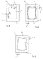
- a direction perpendicular to its feed direction is shown 22 oriented sheet material, for example a printed sheet 1 out.
- the printed sheet 1 contains a printed image on its surface 2, which is surrounded by a frame-like edge 3.
- the inside of the Printing area 2 and the frame 3 marked deviations of ⁇ x and ⁇ y, respectively Denoting position errors in the x and y directions 4 and 5 can occur when printing of the printed image 2 on the surface of the printed sheet 1.
- the Deviations designated by reference numerals 4 and 5 are positional deviations, whereas in the illustration according to FIG. 2 angular deviations ⁇ ⁇ of the printed image two shown in relation to its position on the printed sheet 1 are.
- the angle errors ⁇ that occur are also included Reference numeral 6 marked.
- the printed image 2 can be indicated in the Positions are printed on the surface of the printing material 1, this being conveyed in the sheet running direction with its front edge 23 ahead.
- FIG. 3 shows the so-called in a schematic view Reversing register, with the reference numeral 7 between the printed images 2nd on the front and back of the sheet material 1 each adjusting Offsets are characterized. These are shown in the illustration in FIG Reference numeral 7 or designated and.
- the turning register plays in particular a role in translucent papers of low grammage and extreme light paper weight and brochure printing.
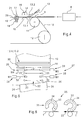
- FIG. 4 shows schematically Side view of the intersection of arch alignment and the emergence on one Conveyor belt.
- the aligned arc-shaped Material 1 on the surface of the conveyor belt 10 in the conveyor plane 9 Passage of the roller 11 is the arcuate material 1 by means of a flap or positioning lip, which can be moved in the direction of adjustment 13.
- the positioning lip or positioning flap can be a plastic component which is made of an employed position 13.1 are moved to a parked position 13.2 can.
- the arcuate is pressed on by means of the adjustment flap or adjustment lip Material 1 on the surface of the conveyor belt 10, wherein in Moment of starting the sheet material 1 in its aligned Condition.
- the pressure element After the pressure element has passed, it passes through the Surface of the conveyor belt 10 received sheets a loading unit 14.
- This charging unit 14 is a within a hood-shaped cover Electrode 15 added, which is used for static charging of the arcuate Material 1 and thus for its adhesion to the surface of it supporting conveyor belt 10 provides.
- the charging unit 14, which in the 4 is only shown schematically, is a leading edge sensor 17 subordinate. This consists of one below the sheet conveying plane 3 arranged radiation source 18, the lens arrangement 19 is connected upstream.
- the A receiver 21 is arranged downstream of the diaphragm arrangement, which accordingly the presence of the radiation shining through the diaphragm arrangement a leading edge 23 of the sheet material 1 sensed and reported.
- the alignment unit 8 is achieved by an arcuate material 1, which is conveyed in the conveying direction 22.
- the leading edge 23 of the arcuate Material 1 is arcuate with respect to the conveying direction 22 Material 1 offset, whereby there is also an oblique course of the side edge 24 of the sheet material 1 sets.
- the drives 27, designated M1 and M2 which have individual axes 32 drive rotary elements 25, at feed speed accelerated.
- This light barrier 30.1 can for example a CCD sensor line 30 can be arranged downstream, which is essentially extends perpendicular to the running direction of the sheet material 1.
- the side regions can be configured in a line-like manner in the sensor line 30 capture all common print media formats.
- a counter unit begins to count in motor steps.
- the counting process is then ended and the determined Difference saved when the second sensor of the light barrier 30.1 on.
- the CCD sensor lines of the sensor pair 30 are thus in the sheet running plane admitted that they are not transporting the sheet material 1 hinder.
- the counter reading determined in this way becomes a correction value determined as an additional feed to the segment roller drive that was started last is passed on, i.e. either the drive 27, designated M 1 is, or to the drive 27, which is designated M 2.
- the sheet-like material 1 becomes 22 in the conveying direction promoted by the first pair of segment rollers 25 to the downstream one Pass a pair of rotary bodies 25, which on a common axis 31st can be included. Now this is via the drive 27 or M 1 and the drive 27 (M 2) driven segment roller pair 25 switched off and moves in its rest position, in which it is with the arcuate material 1 does not touch its peripheral surfaces.
- the rotation elements 25 are in preferred embodiment formed as segment rollers, one by one Have interruption marked circumferential surface 33.
- the segment roles 25 rotate in the direction of rotation 34, indicated by the arrow and shown describe about a 3/4 circle with respect to their respective axis of rotation. Below the respective segment roller 25 is a curved material 1 supporting role shown.
- a pair of CCD line sensors 30 can be used to maintain that side edge 24 at the lateral alignment of the sheet material 1 are made possible Already in the first printing pass to align the sheet material 1 served. If the sheet already printed in the first printing pass becomes Material 1 is printed again in the same printing units, this is where it comes from Side edge 24 after turning around the central axis of the sheet material 1 to lie above the respective other sensor of the line sensor pair 30, so that the alignment takes place on the same side edge 24. Will be with both Alignment operations the same measuring point in the area of the leading edge of the Side edges 24 used, so is the registration for the positioning of Top sides to bottom side printing regardless of the direction of the paper tolerances.
- the proposed method for aligning the sheet material 1 before the running onto a conveyor belt 10 can of course also be done conventionally operable rotary printing presses that use sheet-like material 1 Process, use.
- the line sensor pair 30 is at the end of the feed table to be arranged directly in the area of the side and draw marks, which one Are pre-gripping device with which the aligned arcuate Material 1 accelerated to machine speed and on paper-carrying cylinder is passed.
Landscapes
- Registering Or Overturning Sheets (AREA)
- Shaping Of Tube Ends By Bending Or Straightening (AREA)
- Laminated Bodies (AREA)
- Inking, Control Or Cleaning Of Printing Machines (AREA)
- Casting Or Compression Moulding Of Plastics Or The Like (AREA)
- Cell Separators (AREA)
Abstract
Description
- Figur 1
- eine sich einstellende Lageabweichung eines bedruckten Druckbildes relativ zur dieses aufnehmenden Bedruckstofffläche,
- Figur 2
- eine durch einen Drehversatz gekennzeichneten Versatz des Druckbildes auf dem bogenförmigen Material,
- Figur 3
- einen Versatz der auf Unterseite und Oberseite eines bogenförmigen Materials in Schön- und Wiederdruck aufgedruckten Druckbildes,
- Figur 4
- die Seitenansicht eines Bogeneinlaufbereiches einer bogenverarbeitenden Maschine in schematischer Wiedergabe,
- Figur 5
- die Draufsicht auf die Ausrichtekomponenten, die Sensorik sowie die Antriebe für das bogenförmige Material relativ zu dessen Laufrichtung ausrichtenden Rotationselementen,
- Figur 6
- die oberhalb der Bogenförderebene des bogenförmigen Materials als Segmentrollen ausgebildeten Rotationselemente und
- Figur 7
- die Ausrichtung eines bogenförmigen Materials mit den Antrieben der die Ausrichtung bewirkenden Segmentrollen.
- 1
- bogenförmiges Material
- 2
- Druckbild
- 3
- Rahmen
- 4
- Lagefehler Y-Richtung
- 5
- Lagefehler X-Richtung
- 6
- Verdrehfehler
- 7
- Versatzdruckboden Vorder- und Rückseite (1)
- 8
- Ausrichteeinheit
- 9
- Förderebene
- 10
- Transportband
- 11
- Auflaufrolle
- 12
- Steuerrolle
- 13
- Anstellrichtung
- 13.1
- erste Position
- 13.2
- zweite Position
- 14
- Ladeeinheit
- 15
- Elektrode
- 16
- Abstützung
- 17
- Vorderkantensensor
- 18
- Strahlungsquelle
- 19
- Linse
- 20
- Strahlungsfeld
- 21
- Strahlungsempfänger
- 22
- Förderrichtung bogenförmiges Material
- 23
- Vorderkante
- 24
- Seitenkante
- 25
- Segmentrollen
- 26
- Lichtschranken
- 27
- Antriebe Segmentrolle
- 28
- erste Orientierung Antrieb
- 29
- zweite Orientierung Antrieb
- 30
- Zeilensensorpaar
- 30.1
- Lichtschranke
- 31
- durchgehende Welle
- 32
- Einzelwelle
- 33
- Segmentrollenumfang
- 34
- Drehrichtung
- 35
- Segmentrolle aktive Position
- 36
- Segmentrolle inaktive Position
Claims (11)
- Verfahren zur Ausrichtung bogenförmigen Materials (1), wobei die Ausrichtung mittels Rotationselementen (25) erfolgt und das bogenförmige Material (1) zum Bedrucken von Vorder- und Rückseite um seine Mittelachse gewendet wird, wobei die Vorderkante (23) des bogenförmigen Materials (1) in ihrer ausgerichteten Position verbleibt, dadurch gekennzeichnet, dass in einer Förderebene (9) ein Sensorpaar (30) aufgenommen ist, mit welchem das bogenförmige Material (1) nach der Wendung um seine Mittelachse an der selben Seitenkante (24) ausgerichtet wird, wie beim Ausrichtevorgang des bogenförmigen Materials (1) vor dessen Wendung um seine Mittelachse.
- Verfahren gemäß Anspruch 1, dadurch gekennzeichnet, dass das Sensorpaar (30) in der Förderebene (9) innerhalb der Bereiche der Seitenkanten (24) des bogenförmigen Materials (1) vorgesehen ist.
- Verfahren gemäß Anspruch 1, dadurch gekennzeichnet, dass zur Ausrichtung des bogenförmigen Materials (1) an der Seitenkante (24) stets der gleiche Messpunkt verwendet wird.
- Verfahren gemäß Anspruch 1, dadurch gekennzeichnet, dass die Bestimmung der Position der Seitenkante (24) des bogenförmigen Materials (1) über einen senkrecht zur Förderrichtung (22) des bogenförmigen Materials (1) orientiertes Sensorarray des Sensorpaares (30) erfolgt.
- Verfahren gemäß Anspruch 1, dadurch gekennzeichnet, dass die Bestimmung der Seitenausrichtung des bogenförmigen Materials (1) in der Förderebene (9) zwei CCD-Sensorzeilen (30) aufgenommen sind.
- Verfahren gemäß Anspruch 1, dadurch gekennzeichnet, dass die Ausrichtung des bogenförmigen Materials (1) in an dessen Vorderkante (23) angrenzenden Bereich der Seitenkanten (24) erfolgt.
- Verfahren gemäß Anspruch 5, dadurch gekennzeichnet, dass während der Wendung des bogenförmigen Materials (1) um seine Mittelachse eine Vertauschung der Lage der Seitenkanten (24) unter Beibehaltung der Position der Vorderkante (23) des bogenförmigen Materials (1) erfolgt.
- Einrichtung zur Ausrichtung des bogenförmigen Materials (1), wobei die Ausrichtung des bogenförmigen Materials (1) mittels Rotationselementen (25) vorgenommen wird und das bogenförmige Material (1) zum Bedrucken von Vorder- und Rückseite um seine Mittelachse gewendet wird, wobei die Vorderkante (23) des bogenförmigen Materials (1) in ihrer ausgerichteten Position verbleibt, dadurch gekennzeichnet, dass in der oberen Förderebene (9) ein Sensorpaar (30) in Zeilenform aufgenommen ist, welches eine Ausrichtung des bogenförmigen Materials (1) nach dessen Wendung um seine Mittelachse an der selben Seitenkante (24) des bogenförmigen Materials ermöglicht.
- Druckmaschine mit einer Zuführeinrichtung für bogenförmiges Material (1), wobei die Ausrichtung des bogenförmigen Materials (1) mittels Rotationselementen (25) erfolgt und das bogenförmige Material (1) zum Bedrucken von Vorder- und Rückseite um seine Mittelachse gewendet wird, wobei die Vorderkante (23) des bogenförmigen Materials (1) in ihrer ausgerichteten Position verbleibt, dadurch gekennzeichnet , dass in einer Förderebene (9) ein Sensorpaar (30) aufgenommen ist, mit welchem das bogenförmige Material (1) nach der Wendung um seine Mittelachse an der selben Seitenkante (24) ausgerichtet wird, wie beim Ausrichtevorgang des bogenförmigen Materials vor dessen Wendung um seine Mittelachse.
- Digitaldruckmaschine mit einer Zuführeinrichtung für bogenförmiges Material (1), wobei die Ausrichtung des bogenförmigen Materials (1) mittels Rotationselementen (25) erfolgt und das bogenförmige Material (1) zum Bedrucken von Vorder- und Rückseite um seine Mittelachse gewendet wird, wobei die Vorderkante (23) des bogenförmigen Materials (1) in ihrer ausgerichteten Position verbleibt, dadurch gekennzeichnet, dass in einer Förderebene (9) ein Sensorpaar (30) aufgenommen ist, mit welchem das bogenförmige Material (1) nach der Wendung um seine Mittelachse an derselben Seitenkante (24) ausgerichtet wird, wie beim Ausrichtevorgang des bogenförmigen Materials (1) vor dessen Wendung um seine Mittelachse.
- Elektrografischer Drucker mit einer Zuführeinrichtung für bogenförmiges Material (1), wobei die Ausrichtung des bogenförmigen Materials (1) mittel Rotationselementen (25) erfolgt und das bogenförmige Material (1) zum Bedrucken von Vorder- und Rückseite um seine Mittelachse gewendet wird, wobei die Vorderkante (23) des bogenförmigen Materials (1) in ihrer ausgerichteten Position verbleibt, dadurch gekennzeichnet, dass in einer Förderebene (9) ein Sensorpaar (30) aufgenommen ist, mit welchem das bogenförmige Material (1) nach der Wendung um seine Mittelachse an derselben Seitenkante (24) ausgerichtet wird, wie beim Ausrichtevorgang des bogenförmigen Materials (1) vor dessen Wendung um seine Mittelachse.
Applications Claiming Priority (2)
| Application Number | Priority Date | Filing Date | Title |
|---|---|---|---|
| DE10023919 | 2000-05-17 | ||
| DE10023919A DE10023919A1 (de) | 2000-05-17 | 2000-05-17 | Verfahren zur Ausrichtung bogenförmigen Materials |
Publications (3)
| Publication Number | Publication Date |
|---|---|
| EP1170237A2 true EP1170237A2 (de) | 2002-01-09 |
| EP1170237A3 EP1170237A3 (de) | 2003-01-29 |
| EP1170237B1 EP1170237B1 (de) | 2006-07-12 |
Family
ID=7642223
Family Applications (1)
| Application Number | Title | Priority Date | Filing Date |
|---|---|---|---|
| EP01110274A Expired - Lifetime EP1170237B1 (de) | 2000-05-17 | 2001-04-26 | Verfahren zur Ausrichtung bogenförmigen Materials |
Country Status (5)
| Country | Link |
|---|---|
| US (1) | US20020017755A1 (de) |
| EP (1) | EP1170237B1 (de) |
| JP (1) | JP2002019999A (de) |
| AT (1) | ATE332863T1 (de) |
| DE (2) | DE10023919A1 (de) |
Cited By (1)
| Publication number | Priority date | Publication date | Assignee | Title |
|---|---|---|---|---|
| US8342517B2 (en) | 2009-08-27 | 2013-01-01 | Canon Kabushiki Kaisha | Image forming apparatus |
Families Citing this family (10)
| Publication number | Priority date | Publication date | Assignee | Title |
|---|---|---|---|---|
| US6761351B1 (en) * | 2003-01-30 | 2004-07-13 | Xerox Corporation | Registration system effective drive roll radius compensation |
| US7036811B2 (en) * | 2003-01-30 | 2006-05-02 | Xerox Corporation | Registration system paper path length compensation |
| DE102005060772B4 (de) * | 2005-12-16 | 2010-02-18 | Eastman Kodak Co. | Verfahren zur Erkennung einer Kante eines Bedruckstoffes |
| US7712737B2 (en) * | 2006-12-06 | 2010-05-11 | Xerox Corporation | Gain-scheduled feedback document handling control system |
| US7712738B2 (en) * | 2006-12-06 | 2010-05-11 | Xerox Corporation | Gain-scheduled feedback document handling control system |
| JP5043492B2 (ja) | 2007-04-02 | 2012-10-10 | キヤノン株式会社 | シート搬送装置及び画像形成装置 |
| JP4958670B2 (ja) * | 2007-07-24 | 2012-06-20 | キヤノン株式会社 | 画像処理装置 |
| JP2011153032A (ja) * | 2011-05-19 | 2011-08-11 | Ricoh Co Ltd | シート搬送装置および画像形成装置 |
| JP5822585B2 (ja) | 2011-07-28 | 2015-11-24 | キヤノン株式会社 | 画像形成装置 |
| JP6769266B2 (ja) * | 2016-11-30 | 2020-10-14 | コニカミノルタ株式会社 | 画像形成装置 |
Family Cites Families (10)
| Publication number | Priority date | Publication date | Assignee | Title |
|---|---|---|---|---|
| US4755855A (en) * | 1985-05-30 | 1988-07-05 | Kabushiki Kaisha Toshiba | Image forming apparatus with a forming position correcting function |
| JPH04362661A (ja) * | 1991-06-10 | 1992-12-15 | Fuji Xerox Co Ltd | 画像形成装置の用紙反転搬送装置 |
| US5293205A (en) * | 1992-01-13 | 1994-03-08 | Delphax Systems | Side to side sheet inverter |
| US5322273A (en) * | 1993-05-18 | 1994-06-21 | Eastman Kodak Company | Sheet registration mechanism |
| JPH08143185A (ja) * | 1994-11-25 | 1996-06-04 | Ricoh Co Ltd | 画像形成装置 |
| JPH09267528A (ja) * | 1996-03-29 | 1997-10-14 | Ricoh Co Ltd | 記録紙反転装置 |
| US5697609A (en) * | 1996-06-26 | 1997-12-16 | Xerox Corporation | Lateral sheet pre-registration device |
| NL1003631C2 (nl) * | 1996-07-18 | 1998-01-21 | Oce Tech Bv | Afdrukinrichting met rechtlegstation voor het aan weerszijden bedrukken van rechtgelegde ontvangstvellen. |
| JPH10153891A (ja) * | 1996-11-25 | 1998-06-09 | Fuji Xerox Co Ltd | 画像形成装置 |
| US5887996A (en) * | 1998-01-08 | 1999-03-30 | Xerox Corporation | Apparatus and method for sheet registration using a single sensor |
-
2000
- 2000-05-17 DE DE10023919A patent/DE10023919A1/de not_active Withdrawn
-
2001
- 2001-04-26 DE DE50110435T patent/DE50110435D1/de not_active Expired - Lifetime
- 2001-04-26 AT AT01110274T patent/ATE332863T1/de not_active IP Right Cessation
- 2001-04-26 EP EP01110274A patent/EP1170237B1/de not_active Expired - Lifetime
- 2001-05-15 US US09/855,479 patent/US20020017755A1/en not_active Abandoned
- 2001-05-17 JP JP2001147606A patent/JP2002019999A/ja active Pending
Cited By (1)
| Publication number | Priority date | Publication date | Assignee | Title |
|---|---|---|---|---|
| US8342517B2 (en) | 2009-08-27 | 2013-01-01 | Canon Kabushiki Kaisha | Image forming apparatus |
Also Published As
| Publication number | Publication date |
|---|---|
| EP1170237A3 (de) | 2003-01-29 |
| DE10023919A1 (de) | 2001-11-22 |
| US20020017755A1 (en) | 2002-02-14 |
| ATE332863T1 (de) | 2006-08-15 |
| EP1170237B1 (de) | 2006-07-12 |
| JP2002019999A (ja) | 2002-01-23 |
| DE50110435D1 (de) | 2006-08-24 |
Similar Documents
| Publication | Publication Date | Title |
|---|---|---|
| DE10023940B4 (de) | Vorrichtung zum Ausrichten bogenförmigen Materials während des Transports | |
| EP1345829B1 (de) | Vorrichtung und ein verfahren zur ausrichtung von bogen | |
| EP1170237B1 (de) | Verfahren zur Ausrichtung bogenförmigen Materials | |
| DE19950603B4 (de) | Verfahren zur Steuerung der Bogenzufuhr zu einer bogenverarbeitenden Maschine | |
| EP1170232B1 (de) | Ausrichteeinheit für bogenförmiges Material | |
| DE10152843A1 (de) | Vorrichtung zur Anpassung der Lage bogenförmigen Material bei Bewegungsrichtungsumkehr | |
| EP1170233B1 (de) | Ausrichteeinheit für bogenförmiges Material | |
| EP1170236B1 (de) | Verfahren zur Ausrichtung bogenförmigen Materials an einer Referenzkante | |
| DE102017212134B4 (de) | Bogenverarbeitende Maschine | |
| EP1170235B1 (de) | Verfahren zur Kompensation von Abmessungsänderungen an bogenförmigem Material | |
| DE102017212137B4 (de) | Bogenverarbeitende Maschine | |
| DE10028070B4 (de) | Vorrichtung zur formatabhängigen Lageerfassung der Bogenvorderkante im Anleger von bogenverarbeitenden Maschinen | |
| DE102017212132B4 (de) | Bogenverarbeitende Maschine | |
| DE102017212143B4 (de) | Bogenverarbeitende Maschine | |
| DE102017212141B4 (de) | Bogenverarbeitende Maschine | |
| DE10248687A1 (de) | Verfahren und Vorrichtung zum Zuführen von Bogen zu einer drucktechnischen Maschine | |
| DE102017212140B4 (de) | Bogenverarbeitende Maschine | |
| DE102017212133B4 (de) | Bogenverarbeitende Maschine und Verfahren zum Betreiben einer bogenverarbeitenden Maschine | |
| DE102011087623A1 (de) | Bogenzuführvorrichtung einer Bogendruckmaschine mit einer Mehrfachbogenkontrolleinrichtung und Verfahren zur Detektion von Fehlern im Bogenschuppenstrom | |
| DE102017012188A1 (de) | Bogenverarbeitende Maschine | |
| DE102017012187B4 (de) | Bogenverarbeitende Maschine | |
| DE102012012020A1 (de) | Verfahren zum Zuführen eines Bogens zu einer Maschine | |
| EP2660172A2 (de) | Falschbogenkontrolle einer Bogendruckmaschine | |
| DE10146923A1 (de) | Vorrichtung zum rotativen Bearbeiten von blattförmigen Bedruckstoffen | |
| EP0989083A2 (de) | Falzbogenanleger für Sammelhefter |
Legal Events
| Date | Code | Title | Description |
|---|---|---|---|
| PUAI | Public reference made under article 153(3) epc to a published international application that has entered the european phase |
Free format text: ORIGINAL CODE: 0009012 |
|
| AK | Designated contracting states |
Kind code of ref document: A2 Designated state(s): AT BE CH CY DE DK ES FI FR GB GR IE IT LI LU MC NL PT SE TR |
|
| AX | Request for extension of the european patent |
Free format text: AL;LT;LV;MK;RO;SI |
|
| PUAL | Search report despatched |
Free format text: ORIGINAL CODE: 0009013 |
|
| AK | Designated contracting states |
Designated state(s): AT BE CH CY DE DK ES FI FR GB GR IE IT LI LU MC NL PT SE TR |
|
| AX | Request for extension of the european patent |
Extension state: AL LT LV MK RO SI |
|
| 17P | Request for examination filed |
Effective date: 20030729 |
|
| AKX | Designation fees paid |
Designated state(s): AT BE CH CY DE DK ES FI FR GB GR IE IT LI LU MC NL PT SE TR |
|
| 17Q | First examination report despatched |
Effective date: 20040624 |
|
| RAP1 | Party data changed (applicant data changed or rights of an application transferred) |
Owner name: EASTMAN KODAK COMPANY |
|
| GRAP | Despatch of communication of intention to grant a patent |
Free format text: ORIGINAL CODE: EPIDOSNIGR1 |
|
| GRAS | Grant fee paid |
Free format text: ORIGINAL CODE: EPIDOSNIGR3 |
|
| RIN1 | Information on inventor provided before grant (corrected) |
Inventor name: HAUPT, JOACHIM Inventor name: DOBBERSTEIN, DIETER Inventor name: SING, GERHARD Inventor name: STAACK, HANS-GUENTER Inventor name: PIEREL, FRANK Inventor name: PETER, KARLHEINZ, DR. Inventor name: SPILZ, ROLF Inventor name: SAHLMANN, JUERGEN |
|
| GRAA | (expected) grant |
Free format text: ORIGINAL CODE: 0009210 |
|
| AK | Designated contracting states |
Kind code of ref document: B1 Designated state(s): AT BE CH CY DE DK ES FI FR GB GR IE IT LI LU MC NL PT SE TR |
|
| PG25 | Lapsed in a contracting state [announced via postgrant information from national office to epo] |
Ref country code: IT Free format text: LAPSE BECAUSE OF FAILURE TO SUBMIT A TRANSLATION OF THE DESCRIPTION OR TO PAY THE FEE WITHIN THE PRE;WARNING: LAPSES OF ITALIAN PATENTS WITH EFFECTIVE DATE BEFORE 2007 MAY HAVE OCCURRED AT ANY TIME BEFORE 2007. THE CORRECT EFFECTIVE DATE MAY BE DIFFERENT FROM THE ONE RECORDED.SCRIBED TIME-LIMIT Effective date: 20060712 Ref country code: IE Free format text: LAPSE BECAUSE OF FAILURE TO SUBMIT A TRANSLATION OF THE DESCRIPTION OR TO PAY THE FEE WITHIN THE PRESCRIBED TIME-LIMIT Effective date: 20060712 Ref country code: FI Free format text: LAPSE BECAUSE OF FAILURE TO SUBMIT A TRANSLATION OF THE DESCRIPTION OR TO PAY THE FEE WITHIN THE PRESCRIBED TIME-LIMIT Effective date: 20060712 |
|
| REG | Reference to a national code |
Ref country code: GB Ref legal event code: FG4D Free format text: NOT ENGLISH |
|
| REG | Reference to a national code |
Ref country code: CH Ref legal event code: EP |
|
| GBT | Gb: translation of ep patent filed (gb section 77(6)(a)/1977) |
Effective date: 20060719 |
|
| REG | Reference to a national code |
Ref country code: IE Ref legal event code: FG4D Free format text: LANGUAGE OF EP DOCUMENT: GERMAN |
|
| REF | Corresponds to: |
Ref document number: 50110435 Country of ref document: DE Date of ref document: 20060824 Kind code of ref document: P |
|
| PG25 | Lapsed in a contracting state [announced via postgrant information from national office to epo] |
Ref country code: SE Free format text: LAPSE BECAUSE OF FAILURE TO SUBMIT A TRANSLATION OF THE DESCRIPTION OR TO PAY THE FEE WITHIN THE PRESCRIBED TIME-LIMIT Effective date: 20061012 Ref country code: DK Free format text: LAPSE BECAUSE OF FAILURE TO SUBMIT A TRANSLATION OF THE DESCRIPTION OR TO PAY THE FEE WITHIN THE PRESCRIBED TIME-LIMIT Effective date: 20061012 |
|
| PG25 | Lapsed in a contracting state [announced via postgrant information from national office to epo] |
Ref country code: ES Free format text: LAPSE BECAUSE OF FAILURE TO SUBMIT A TRANSLATION OF THE DESCRIPTION OR TO PAY THE FEE WITHIN THE PRESCRIBED TIME-LIMIT Effective date: 20061023 |
|
| PG25 | Lapsed in a contracting state [announced via postgrant information from national office to epo] |
Ref country code: PT Free format text: LAPSE BECAUSE OF FAILURE TO SUBMIT A TRANSLATION OF THE DESCRIPTION OR TO PAY THE FEE WITHIN THE PRESCRIBED TIME-LIMIT Effective date: 20061212 |
|
| REG | Reference to a national code |
Ref country code: IE Ref legal event code: FD4D |
|
| EN | Fr: translation not filed | ||
| PLBE | No opposition filed within time limit |
Free format text: ORIGINAL CODE: 0009261 |
|
| STAA | Information on the status of an ep patent application or granted ep patent |
Free format text: STATUS: NO OPPOSITION FILED WITHIN TIME LIMIT |
|
| 26N | No opposition filed |
Effective date: 20070413 |
|
| REG | Reference to a national code |
Ref country code: CH Ref legal event code: PL |
|
| BERE | Be: lapsed |
Owner name: EASTMAN KODAK CY Effective date: 20070430 |
|
| PG25 | Lapsed in a contracting state [announced via postgrant information from national office to epo] |
Ref country code: LI Free format text: LAPSE BECAUSE OF NON-PAYMENT OF DUE FEES Effective date: 20070430 Ref country code: CH Free format text: LAPSE BECAUSE OF NON-PAYMENT OF DUE FEES Effective date: 20070430 |
|
| PG25 | Lapsed in a contracting state [announced via postgrant information from national office to epo] |
Ref country code: BE Free format text: LAPSE BECAUSE OF NON-PAYMENT OF DUE FEES Effective date: 20070430 |
|
| PG25 | Lapsed in a contracting state [announced via postgrant information from national office to epo] |
Ref country code: FR Free format text: LAPSE BECAUSE OF FAILURE TO SUBMIT A TRANSLATION OF THE DESCRIPTION OR TO PAY THE FEE WITHIN THE PRESCRIBED TIME-LIMIT Effective date: 20070511 Ref country code: GR Free format text: LAPSE BECAUSE OF FAILURE TO SUBMIT A TRANSLATION OF THE DESCRIPTION OR TO PAY THE FEE WITHIN THE PRESCRIBED TIME-LIMIT Effective date: 20061013 |
|
| PG25 | Lapsed in a contracting state [announced via postgrant information from national office to epo] |
Ref country code: AT Free format text: LAPSE BECAUSE OF NON-PAYMENT OF DUE FEES Effective date: 20070426 |
|
| PG25 | Lapsed in a contracting state [announced via postgrant information from national office to epo] |
Ref country code: FR Free format text: LAPSE BECAUSE OF FAILURE TO SUBMIT A TRANSLATION OF THE DESCRIPTION OR TO PAY THE FEE WITHIN THE PRESCRIBED TIME-LIMIT Effective date: 20060712 |
|
| PG25 | Lapsed in a contracting state [announced via postgrant information from national office to epo] |
Ref country code: MC Free format text: LAPSE BECAUSE OF NON-PAYMENT OF DUE FEES Effective date: 20070430 |
|
| PG25 | Lapsed in a contracting state [announced via postgrant information from national office to epo] |
Ref country code: LU Free format text: LAPSE BECAUSE OF NON-PAYMENT OF DUE FEES Effective date: 20070426 Ref country code: CY Free format text: LAPSE BECAUSE OF FAILURE TO SUBMIT A TRANSLATION OF THE DESCRIPTION OR TO PAY THE FEE WITHIN THE PRESCRIBED TIME-LIMIT Effective date: 20060712 |
|
| PG25 | Lapsed in a contracting state [announced via postgrant information from national office to epo] |
Ref country code: TR Free format text: LAPSE BECAUSE OF FAILURE TO SUBMIT A TRANSLATION OF THE DESCRIPTION OR TO PAY THE FEE WITHIN THE PRESCRIBED TIME-LIMIT Effective date: 20060712 |
|
| PGFP | Annual fee paid to national office [announced via postgrant information from national office to epo] |
Ref country code: GB Payment date: 20130326 Year of fee payment: 13 |
|
| PGFP | Annual fee paid to national office [announced via postgrant information from national office to epo] |
Ref country code: DE Payment date: 20130430 Year of fee payment: 13 |
|
| PGFP | Annual fee paid to national office [announced via postgrant information from national office to epo] |
Ref country code: NL Payment date: 20130409 Year of fee payment: 13 |
|
| REG | Reference to a national code |
Ref country code: DE Ref legal event code: R119 Ref document number: 50110435 Country of ref document: DE |
|
| REG | Reference to a national code |
Ref country code: NL Ref legal event code: V1 Effective date: 20141101 |
|
| GBPC | Gb: european patent ceased through non-payment of renewal fee |
Effective date: 20140426 |
|
| PG25 | Lapsed in a contracting state [announced via postgrant information from national office to epo] |
Ref country code: GB Free format text: LAPSE BECAUSE OF NON-PAYMENT OF DUE FEES Effective date: 20140426 Ref country code: DE Free format text: LAPSE BECAUSE OF NON-PAYMENT OF DUE FEES Effective date: 20141101 |
|
| REG | Reference to a national code |
Ref country code: DE Ref legal event code: R119 Ref document number: 50110435 Country of ref document: DE Effective date: 20141101 |
|
| PG25 | Lapsed in a contracting state [announced via postgrant information from national office to epo] |
Ref country code: NL Free format text: LAPSE BECAUSE OF NON-PAYMENT OF DUE FEES Effective date: 20141101 |