EP1170182B1 - Drehpositionssensor und Scheibenwischervorrichtung damit - Google Patents
Drehpositionssensor und Scheibenwischervorrichtung damit Download PDFInfo
- Publication number
- EP1170182B1 EP1170182B1 EP01115477A EP01115477A EP1170182B1 EP 1170182 B1 EP1170182 B1 EP 1170182B1 EP 01115477 A EP01115477 A EP 01115477A EP 01115477 A EP01115477 A EP 01115477A EP 1170182 B1 EP1170182 B1 EP 1170182B1
- Authority
- EP
- European Patent Office
- Prior art keywords
- follower
- rotational
- engaging
- sensing device
- side engaging
- Prior art date
- Legal status (The legal status is an assumption and is not a legal conclusion. Google has not performed a legal analysis and makes no representation as to the accuracy of the status listed.)
- Expired - Lifetime
Links
Images


Classifications
-
- B—PERFORMING OPERATIONS; TRANSPORTING
- B60—VEHICLES IN GENERAL
- B60S—SERVICING, CLEANING, REPAIRING, SUPPORTING, LIFTING, OR MANOEUVRING OF VEHICLES, NOT OTHERWISE PROVIDED FOR
- B60S1/00—Cleaning of vehicles
- B60S1/02—Cleaning windscreens, windows or optical devices
- B60S1/04—Wipers or the like, e.g. scrapers
- B60S1/06—Wipers or the like, e.g. scrapers characterised by the drive
- B60S1/08—Wipers or the like, e.g. scrapers characterised by the drive electrically driven
-
- B—PERFORMING OPERATIONS; TRANSPORTING
- B60—VEHICLES IN GENERAL
- B60S—SERVICING, CLEANING, REPAIRING, SUPPORTING, LIFTING, OR MANOEUVRING OF VEHICLES, NOT OTHERWISE PROVIDED FOR
- B60S1/00—Cleaning of vehicles
- B60S1/02—Cleaning windscreens, windows or optical devices
- B60S1/04—Wipers or the like, e.g. scrapers
- B60S1/06—Wipers or the like, e.g. scrapers characterised by the drive
- B60S1/16—Means for transmitting drive
- B60S1/166—Means for transmitting drive characterised by the combination of a motor-reduction unit and a mechanism for converting rotary into oscillatory movement
-
- H—ELECTRICITY
- H01—ELECTRIC ELEMENTS
- H01H—ELECTRIC SWITCHES; RELAYS; SELECTORS; EMERGENCY PROTECTIVE DEVICES
- H01H19/00—Switches operated by an operating part which is rotatable about a longitudinal axis thereof and which is acted upon directly by a solid body external to the switch, e.g. by a hand
- H01H19/54—Switches operated by an operating part which is rotatable about a longitudinal axis thereof and which is acted upon directly by a solid body external to the switch, e.g. by a hand the operating part having at least five or an unspecified number of operative positions
- H01H19/56—Angularly-movable actuating part carrying contacts, e.g. drum switch
- H01H19/58—Angularly-movable actuating part carrying contacts, e.g. drum switch having only axial contact pressure, e.g. disc switch, wafer switch
-
- H—ELECTRICITY
- H01—ELECTRIC ELEMENTS
- H01H—ELECTRIC SWITCHES; RELAYS; SELECTORS; EMERGENCY PROTECTIVE DEVICES
- H01H3/00—Mechanisms for operating contacts
- H01H3/32—Driving mechanisms, i.e. for transmitting driving force to the contacts
- H01H3/48—Driving mechanisms, i.e. for transmitting driving force to the contacts using lost-motion device
-
- Y—GENERAL TAGGING OF NEW TECHNOLOGICAL DEVELOPMENTS; GENERAL TAGGING OF CROSS-SECTIONAL TECHNOLOGIES SPANNING OVER SEVERAL SECTIONS OF THE IPC; TECHNICAL SUBJECTS COVERED BY FORMER USPC CROSS-REFERENCE ART COLLECTIONS [XRACs] AND DIGESTS
- Y10—TECHNICAL SUBJECTS COVERED BY FORMER USPC
- Y10S—TECHNICAL SUBJECTS COVERED BY FORMER USPC CROSS-REFERENCE ART COLLECTIONS [XRACs] AND DIGESTS
- Y10S318/00—Electricity: motive power systems
- Y10S318/02—Windshield wiper controls
Definitions
- the present invention relates to a rotational-position sensing device and a windshield wiper system.
- the documents US-A-4700026 and EP-A-0569895 disclose a rotational-position sensing device and a windshield wiper system according to a preamble of independent claims 1 and 13.
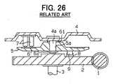
- FIG. 26 shows a rotational-position sensing device for a windshield wiper system disclosed in Japanese Unexamined Utility Model Publication No. 61-35068.
- a worm 1 and a wheel (acting as a rotator) 2 meshed with the worm 1 constitute a speed reducing gear mechanism.
- Rotation of an output shaft 3 secured to the wheel 2 is transmitted to a crank mechanism (not shown) acting as a reciprocating swing mechanism.
- the crank mechanism reciprocally swings wiper blades (not shown) along a windshield.
- a cover 4 that covers a gear case opposes the wheel 2.
- a follower 5 is rotatably supported by a spindle 4a that protrudes from the cover 4.
- a switching pattern 6 is arranged in an opposing surface of the follower 5 that opposes the cover 4.
- a plurality of contact terminals 7 are arranged in an opposing surface of the cover 4 that opposes the follower 5. The rotation of the wheel 2, which generates the swing motion of the wiper blades, is transmitted to the follower 5 through engagement between a protrusion 8 of the wheel 2 and a protrusion 9 of the follower 5, so that the follower 5 is integrally rotated with the wheel 2. As the follower 5 rotates, the contact terminals 7 engage and disengage with the switching pattern 6, so that a rotational position of the wheel 2 or a rotational position of the output shaft 3 is sensed or detected.
- the contact terminals 7 are urged against the switching pattern 6 because of their own resilient forces.
- the resilient forces of the contact terminals 7 are summed and are applied to the follower 5 to lever the follower 5 about the spindle 4a, the follower 5 tilts with respect to the spindle 4a.
- the follower 5 tilts the follower 5 cannot rotate freely, causing an increased rotational resistance of the follower 5.
- the increase in the rotational resistance of the follower 5 normally results in a decrease in a transmission efficiency of the power transmission system between a wiper drive motor and the follower 5.
- the tilt of the follower 5 may cause a contact failure between the contact terminals 7 and the switching pattern 6. Such a contact failure causes a reduction in a sensing accuracy of the rotational-position sensing device.
- a wave washer 61 is inserted around the spindle 4a to urge the follower 5 in an axial direction away from it, and a stationary engaging member 62, such as a C-ring, is fitted around the spindle 4a to hold the follower 5 in place around the spindle 4a.
- the wiper blades are controlled to be stopped at a predetermined stop position which is generally one swing end position of the wiper blades. More specifically, when a vehicle driver manually turns off a wiper switch, the following control operation is conducted. That is, the wiper drive motor drives the wiper blades to the predetermined stop position and then stops the wiper blades in the predetermined stop position.
- This type of automatic stop arrangement for automatically stops the wiper blades in the predetermined stop position is disclosed in Japanese Unexamined Utility Model Publication No. 61-35068. By way of example, it will be assumed that a relatively large amount of snow is present on the windshield. In the windshield wiper system having the automatic stop arrangement, the wiper blades wipe the snow toward the predetermined stop position.
- the wiper drive motor When the wiper blades reach the predetermined stop position, the wiper drive motor is turned off, so that the wiper blades lose its driving force. Since the snow has been packed by the wiper blades, the snow exerts a reaction force against the wiper blades to move the wiper blades backward out of the predetermined stop position, and the wiper drive motor is forced to rotate backward.
- the follower 5 is rotated backward due to the backward rotation of the wiper drive motor, a state of engagement and disengagement between the switching pattern 6 and the contact terminals 7 is changed to another state different from one that is seen while the wiper blades are held in the stop position. This change in the state of engagement and disengagement causes the wiper drive motor to drive the wiper blades toward the stop position. This results in chattering of the wiper system.
- the contact terminals 7 need to be secured to the cover 4 in manufacturing. Furthermore, the switching pattern 6 and the protrusion 9 need to be provided in the follower 5. Thus, a number of components to be assembled is increased. Because of this, parts management becomes more complicated, and a number of assembling steps is disadvantageously increased.
- the present invention addresses the above disadvantages.
- a rotational-position sensing device including a stationary body, a rotator and a follower.
- the stationary body includes a switching pattern.
- the rotator is rotatably supported by the stationary body.
- the rotator has a driving-side engaging means.
- the switching pattern is provided around a rotational axis of the rotator.
- the follower receives a rotational force to rotate about the rotational axis from the rotator through the driving-side engaging means.
- the follower includes a plurality of contact terminals.
- the rotational-position sensing device senses a rotational position of the rotator through engagement and disengagement of the contact terminals with the switching pattern based on rotation of the follower.
- the follower is made of an electrically conductive metal plate, which has a resiliency.
- the contact terminals are integrally formed in the electrically conductive metal plate.
- the follower further includes a driven-side engaging means that receives the rotational force from the rotator during rotation of the rotator in a forward rotational direction upon engagement with the driving-side engaging means in a forward rotational engaged position.
- the driven-side engaging means has a play. The play allows the driving-side engaging means to move away from the forward rotational engaged position without transmitting the rotational force to the follower when the rotator rotates in a backward rotational direction.
- one of said driving-side engaging means and said driven-side engaging means is an engaging protrusion
- the other of said driving-side engaging means and said driven-side engaging means is one of an engaging recess and on engaging hole, to which said engaging protrusion is engaged
- said contact terminals are manufactured by cutting and bending said electrically conductive metal plate.
- a windshield wiper system having a wiper arm with a wiper blade connected thereto, a motor and a control device.
- the motor has a rotational-position sensing device for sensing a rotational position of the wiper blade, a gear housing and a speed reducing mechanism.
- the gear housing includes a receiving recess and a cover for covering the receiving recess.
- the speed reducing mechanism is received within the receiving recess.
- the speed reducing mechanism is connected to an output shaft for outputting a rotational force of the speed reducing mechanism.
- the control device includes a wiper switch and controls the motor based on an operation mode selected through the wiper switch.
- the wiper arm and the wiper blade are reciprocally swung by a rotational driving force of the motor.
- the rotational-position sensing device includes a rotator, a switching pattern and a follower.
- the rotator is rotatably supported by the gear housing.
- the rotator has a driving-side engaging means and rotates integrally with the output shaft.
- the switching pattern is formed in the cover around a rotational axis of the rotator.
- the switching pattern includes a first rotational position and a second rotational position.
- the first rotational position corresponds to a predetermined stop position of the wiper blade.
- the second rotational position indicates a rotational position of the wiper blade other than the first rotational position of the wiper blade.
- the follower is made of an electrically conductive metal plate, which has resiliency.
- the follower includes a plurality of contact terminals and a driven-side engaging means.
- the contact terminals are integrally formed in the electrically conductive metal plate.
- the contact terminals engage and disengage with the switching pattern.
- the driven-side engaging means receives a rotational force to rotate about the rotational axis during rotation of the rotator in a forward rotational direction upon engagement with the driving-side engaging means in a forward rotational engaged position.
- the driven-side engaging means has a play. The play allows the driving-side engaging means to move away from the forward rotational engaged position without transmitting the rotational force to the follower when the rotator rotates in a backward rotational direction.
- one of said driving-side engaging means and said driven-side engaging means is an engaging protrusion
- the other of said driving-side engaging means and said driven-side engaging means is one of an engaging recess and on engaging hole, to which said engaging protrusion is engaged
- said contact terminals are manufactured by cutting and bending said electrically conductive metal plate.
- a rotational-position sensing device including a stationary body, a rotator, a follower, a switching pattern and a plurality of contact terminals.
- the rotator is rotatably supported by the stationary body.
- the follower is rotatably supported by a support element provided on the stationary body.
- the support element is coaxial with the rotator.
- the follower is positioned between the stationary body and the rotator and receives a rotational force from the rotator.
- the switching pattern is formed in one of the stationary body and the follower.
- the contact terminals are formed in the other of the stationary body and the follower.
- a rotational position of the rotator is sensed through engagement and disengagement of the contact terminals with the switching pattern based on rotation of the follower.
- a signal indicative of the rotational position of the rotator is outputted from the rotational-position sensing device.
- the rotational-position sensing device further includes a space maintaining means and a cylindrical engaging portion.
- the space maintaining means is provided around the support element to maintain a predetermined space between the follower and an opposing surface of the stationary body that axially opposes the follower.
- the cylindrical engaging portion is provided at a center of the follower.
- the cylindrical engaging portion has a peripheral surface that slidably engages a peripheral surface of the support element.
- a windshield wiper system having a wiper, a reciprocating swing mechanism for reciprocally swinging the wiper, a motor and a speed reducing mechanism.
- the motor has a gear housing.
- the speed reducing mechanism is received in the gear housing to transmit rotation of a motor at a reduced speed.
- the rotation of the motor is transmitted to the wiper through the speed reducing mechanism and the reciprocating swing mechanism to reciprocally swing the wiper.
- the windshield wiper system further includes a rotational-position sensing device and a control device.
- the rotational-position sensing device includes a rotator, a follower, a switching pattern, a plurality of contact terminals and a space maintaining means.
- the rotator is rotatably supported by the gear housing.
- the rotator is integrally rotated with an output shaft that receives a rotational force from the speed reducing mechanism.
- the follower is rotatably supported by a support element provided in the gear housing.
- the support element is coaxial with the rotator.
- the follower is positioned between the gear housing and the rotator and receives a rotational force from the rotator.
- the follower has a cylindrical engaging portion provided at a center of the follower.
- the cylindrical engaging portion has a peripheral surface that slidably engages a peripheral surface of the support element.
- the switching pattern is formed in one of the gear housing and the follower.
- the contact terminals are formed in the other of the gear housing and the follower.
- the space maintaining means is provided around the support element to maintain a predetermined space between the follower and an opposing surface of the gear housing that axially opposes the follower.
- a rotational position of the rotator is sensed through engagement and disengagement of the contact terminals with the switching pattern based on rotation of the follower.
- a signal indicative of the rotational position of the rotator is outputted from the rotational-position sensing device.
- the control device includes a wiper switch that is switched between a stop position and an actuation position. The control device rotates the motor until the rotational-position sensing device senses a rotational position of the rotator that corresponds to a predetermined stop position of the wiper after the wiper switch is switched to the stop position to stop the windshield wiper system. The control device stops the motor when the rotational-position sensing device senses the rotational position of the rotator that corresponds to the predetermined stop position of the wiper.
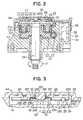
- FIGS. 1-5 A windshield wiper system according to a first embodiment of the present invention will be described with reference to FIGS. 1-5.
- a gear housing 12 is connected to a yoke housing 111 of a wiper drive motor 11.
- a first speed reducing gear mechanism 13 and a second speed reducing gear mechanism 17 are received within the gear housing 12.
- the first speed reducing gear mechanism 13 includes a worm 14 and a worm wheel 15.
- the worm 14 is connected to an armature 112 of the wiper drive motor 11.
- the worm wheel 15 is meshed with the worm 14.
- the worm 14 acts as an output shaft of the wiper drive motor 11.
- the worm wheel 15 is rotatably supported by an output shaft 16, which is, in turn, rotatably supported by the gear housing 12.
- the second speed reducing gear mechanism 17 is a planetary speed reducing gear mechanism including a sun gear 18, a carrier 19, a plurality (three in this embodiment, as shown in FIG. 1) of planet gears 20, an internal gear 21 and an output shaft 16.
- the sun gear 18 is coaxially secured to the worm wheel 15.
- the carrier 19 is secured to the output shaft 16 in opposed relationship with the sun gear 18.
- Each planet gear 20 is rotatably supported by a spindle (support element) 191 that protrudes from the carrier 19.
- the internal gear 21 is secured to an inner peripheral surface of a receiving recess 121 defined in the gear housing 12.
- the worm wheel 15 and the carrier 19 are received within the receiving recess 121.
- the planet gears 20 are meshed with both the sun gear 18 and internal gear 21.
- a rotational axis 161 of the output shaft 16 is also a rotational axis of the carrier 19.
- a rotational speed of the worm 14 is reduced in two steps through the first speed reducing gear mechanism 13 and the second speed reducing gear mechanism 17 before it is transmitted to the output shaft 16.
- the output shaft 16 and the carrier 19 rotate in a direction of an arrow R (this rotational direction is hereinafter referred to as a forward rotational direction R).
- the first speed reducing gear mechanism 13 and the second speed reducing gear mechanism 17 cooperatively constitute a speed reducing mechanism for transmitting the rotation of the worm 14 that acts as the output shaft of the wiper drive motor 11 at a reduced speed.
- a reciprocating swing mechanism of a crank type (not shown), such as one disclosed in Japanese Unexamined Utility Model Publication No. 61-35068, United States Patent No. 5,093,952 is connected to the output shaft 16.
- Wiper arms (not shown) each having a wiper blade (not shown) are operably connected to the reciprocating swing mechanism.
- the wiper blades are reciprocally swung by the reciprocating swing mechanism that is, in turn, driven by the rotation of the output shaft 16.
- the wiper blades reciprocate once per rotation of the output shaft 16.
- the receiving recess 121 is covered with a cover 22 that constitutes a part of the gear housing (stationary body) 12.
- a cylindrical spindle 249 and an annular position-limiting ridge (position-limiting protrusion) 50 protrude from an opposing surface 221 (FIG. 3) of the cover 22 that opposes the carrier 19.
- the annular position-limiting ridge 50 is formed to coaxially surround the spindle 249.
- a follower 23 is rotatably fitted around the spindle 249.
- a central axis of the spindle 249 coincides with the rotational axis 161 of the output shaft 16.
- the follower 23 is made of an electrically conductive metal plate.
- the follower 23 has a circular disk shape (best seen in FIG.
- the cylindrical engaging portion 232 includes a cylindrical engaging portion 232 that protrudes toward the cover 22 at a center of the follower 23.
- the cylindrical engaging portion 232 surrounds the spindle 249.
- the spindle 249 slidably engages an inner peripheral surface 237 of the cylindrical engaging portion 232.
- the follower 23 includes an annular reinforcing wall 233 that is bent to protrude from an outer peripheral edge of the follower 23 toward the cover 22.
- the reinforcing wall 233 increases a rigidity of the plate-like follower 23.
- a portion of the follower 23 located between the reinforcing wall 233 and the cylindrical engaging portion 232 is divided into an annular disk portion 235 and a contact portion 236 by an outer cylindrical portion 234.
- the contact portion 236 opposes a distal end surface 501 of the position-limiting ridge 50.
- the cylindrical engaging portion 232, the reinforcing wall 233 and the outer cylindrical portion 234 are bent by press work.
- a toothed washer 51 is fitted around an outer peripheral surface 491 of the spindle 249.
- the toothed washer 51 includes a tooth portion 511 and an annular flat portion 512.
- the tooth portion 511 is securely engaged into the outer peripheral surface 491.
- the annular flat portion 512 engages the contact portion 236 of the follower 23.
- the toothed washer 51 fitted around the spindle 249 urges the contact portion 236 of the follower 23 against the distal end surface 501 of the position-limiting ridge 50.
- a plurality (three in this embodiment) of lever-like contact terminals 231 are integrally formed in the follower 23.
- each contact terminal 231 is formed by cutting a corresponding portion of the follower 23 and then bending it toward the cover 22.
- a semi-spherical contact 238 is formed at a distal end of each contact terminal 231.
- an engaging hole 24 penetrates through the follower 23.
- the engaging hole 24 is an arcuate hole extending along a circle whose center coincides with the rotational axis 161 of the output shaft 16.
- an engaging protrusion 25 is securely connected to an opposing surface 192 of the carrier 19 that opposes the follower 23.
- a distal end of the engaging protrusion 25 that rotates integrally with the carrier 19 has a cylindrical shape and is received within the engaging hole 24.
- an engaging wall 241 is formed by burring a corresponding portion of the follower 23 in such a manner that the engaging wall 241 protrudes from a peripheral edge of the engaging hole 24.
- the rotation of the carrier 19 is transmitted to the follower 23 through the engagement between the engaging protrusion 25 and the circumferential end 242, so that the follower 23 is dragged to rotate about the spindle 249.
- the follower 23 rotates along with the carrier 19, the inner peripheral surface 237 of the cylindrical engaging portion 232 slides along the outer peripheral surface 491 of the spindle 249, and the contact portion 236 slides along the distal end surface 501 of the position-limiting ridge 50 and the flat portion 512 of the toothed washer 51.
- an electrically conductive switching pattern 26 is secured to the inner surface of the cover 22 around the spindle 249.
- the electrically conductive switching pattern 26 is provided for sensing rotational positions corresponding to a wiping position and a stop position of the wiper blades.
- a circuit unit 27 is received within a receiving portion 122 of the gear housing 12.
- the circuit unit 27 includes brush wiring terminals 28-30, external terminals 31-35, choke coils 36, 37, capacitors 38, 39 and a circuit breaker 40 that acts as an anti-burning means.
- the brush wiring terminal 28 acting as a common ground terminal is connected to the external terminal 31 through the circuit breaker 40.
- the brush wiring terminal 29 provided for a high speed operation is connected to the external terminal 32 through the choke coil 36.
- the brush wiring terminal 30 provided for a low speed operation is connected to the external terminal 33 through the choke coil 37.
- the circuit breaker 40 electrically disconnects the brush wiring terminal 28 from the external terminal 31 upon overheating of the choke coils 36, 37 or of the circuit breaker 40 itself.
- the brush wiring terminal 28 is electrically connected to a common ground brush 41, and the brush wiring terminal 29 is electrically connected to a high speed brush 42.
- the brush wiring terminal 30 is electrically connected to a low speed brush 43. In FIG. 1, only the brushes 41 and 42 are depicted among the brushes 41-43.
- the engagement and disengagement between the contact 238 of each contact terminal 231 and the switching pattern 26 cause electrical connection and electrical disconnection among the external terminals 31, 34 and 35.
- the carrier 19 provided with the engaging protrusion 25, the follower 23 provided with the engaging hole 24 and the contact terminals 231, the cover 22 provided with the switching pattern 26 constitute a rotational-position sensing device 44 for sensing or detecting a rotational position of the carrier 19 acting as a rotator.
- the switching pattern 26 includes first and second rotational positions of the carrier 19. The first rotational position corresponds to a predetermined stop position of the wiper blades (located within a predetermined range in a bottom section of a windshield). The second rotational position corresponds to a rotational position other than the first rotational position.
- the rotational-position sensing device 44 When the wiper blades are in the predetermined stop position, the rotational-position sensing device 44 electrically connects the external terminal 31 to the external terminal 34. That is, the first rotational position is a specific state where the rotational-position sensing device 44 electrically connects the external terminal 31 to the external terminal 34. When the wiper blades are out of the predetermined stop position, the rotational-position sensing device 44 electrically connects the external terminal 34 to the external terminal 35. That is, the second rotational position is another specific state where the rotational-position sensing device 44 electrically connects the external terminal 34 to the external terminal 35.
- a control device 45 is electrically connected to the external terminals 31-35.
- the control device 45 includes a wiper switch 46 and a battery 47.
- the external terminals 32-35 are electrically connected to the wiper switch 46.
- the external terminal 35 is also electrically connected to a cathode of the battery 47, and the external terminal 31 is electrically connected to a ground.
- the wiper switch 46 can be positioned in one of a stop position (stop mode) 461, a low speed operating position (low speed operation mode) 462 and a high speed operating position (high speed operation mode) 463.
- stop mode stop mode
- low speed operating position low speed operation mode
- high speed operation mode high speed operation mode
- the wiper switch 46 When the wiper switch 46 is positioned in the high speed operating position 463, the external terminal 32 is electrically connected to the battery 47 through the wiper switch 46. At this electrically connected state, the electric current is applied to the brush 42 through the brush wiring terminal 29, so that the armature 112 is rotated at a high speed. Thus, the wiper blades swing at the high speed.
- the rotational-position sensing device 44 senses the second rotational position and electrically connects the external terminal 34 to the external terminal 35. Then, the electric current is applied to the brush 43 through the rotational-position sensing device 44 and the wiper switch 46, so that the wiper drive motor 11 is operated at the low speed, and the wiper blades wipe the windshield at the low speed.
- the rotational-position sensing device 44 senses the first rotational position and electrically connects the external terminal 31 to the external terminal 34. That is, when the wiper switch 46 is in the stop position 461 while the external terminal 31 is electrically connected to the external terminal 34 through the rotational-position sensing device 44, there is provided a closed-loop circuit proceeding in the following order: the external terminal 31; the rotational-position sensing device 44; the external terminal 34; the wiper switch 46; the external terminal 33; the choke coil 37; the brush 43; windings of the armature 112; the brush 41; the circuit breaker 40 and the external terminal 31.
- an electrical braking force is applied to the armature 112, so that the rotation of the armature 112 is stopped.
- the wiper blades automatically stop in the predetermined stop position.
- the wiper switch 46, the battery 47, the circuit unit 27 and the rotational-position sensing device 44 constitute an automatic stop arrangement 48 for automatically stops the wiper blades in the predetermined stop position.
- the wiper blades wipe the snow toward the predetermined stop position.
- the wiper drive motor is turned off, so that the wiper blades lose its driving force. Since the snow has been packed by the wiper blades, the snow exerts a reaction force against the wiper blades to move the wiper blades backward out of the predetermined stop position, and the wiper drive motor 11 is forced to rotate backward.
- the external terminal 31 can be disconnected from the external terminal 34, and the external terminal 34 can be electrically connected to the external terminal 35.
- the electric current may be applied to the brush 43, so that wiper blades are urged toward the predetermined stop position by the wiper drive motor 11. This causes chattering of the wiper system.
- a play 244 is provided in the engaging hole 24, so that the engaging protrusion 25 can move within a range of play 244 within the engaging hole 24.
- the engaging protrusion 25 is engaged with the circumferential end 242 of the engaging hole 24, i.e., the follower 23 can be immediately rotated upon rotation of the carrier 19 in the forward rotational direction R without a pause. In this state, if the wiper drive motor 11 is forced to rotate backward, the engaging protrusion 25 is relatively moved from the one circumferential end 242 toward the other circumferential end 243 within the engaging hole 24.
- the rotational-position sensing device 44 acting as a part of the automatic stop arrangement 48 can prevent chattering of the windshield wiper system without changing the state of engagement and disengagement between the switching pattern 26 and each contact terminal 231.
- the first embodiment provides the following advantages.
- the annular position-limiting ridge 50 limits the position of the contact portion 236 of the follower 23 around the spindle 249 in such a manner that the contact portion 236 of the follower 23 is prevented from moving toward the opposing surface 221 of the cover 22 that axially opposes the follower 23.
- the toothed washer 51 limits the position of the contact portion 236 of the follower 23 around the spindle 249 in such a manner that the contact portion 236 of the follower 23 is prevented from moving toward the carrier 19.
- the position-limiting ridge 50 and the toothed washer 51 constitute a space maintaining means for maintaining a predetermined space between the follower 23 and the switching pattern 26 (or between the follower 23 and the opposing surface 221 of the cover 22).
- the cylindrical engaging portion 232 acts as an engaging means for engaging the follower 23 with the spindle 249 while allowing relative rotation therebetween.
- the position-limiting action of the position-limiting ridge 50 against the contact portion 236 of the follower 23 and the position-limiting action of the toothed washer 51 against the contact portion 236 of the follower 23 restrain the follower 23 from moving in the axial direction relative to the spindle 249 throughout the entire peripheral surface of the spindle 249. Movement of the follower 23 in a radial direction of the spindle 249 is restrained by the position-limiting action that is achieved through the engagement between the cylindrical engaging portion 232 and the spindle 249, more specifically the engagement between the cylindrical engaging portion 232 and the outer peripheral surface 491 of the spindle 249.
- the engagement between the cylindrical engaging portion 232 and the spindle 249 restrains tilt of the cylindrical engaging portion 232 relative to the spindle 249.
- the position-limiting action of the position-limiting ridge 50, the position-limiting action of the toothed washer 51 and the position-limiting action of the cylindrical engaging portion 232 cooperate together to effectively restrain the tilt of the follower 23.
- the toothed washer 51 is the only component to be fitted around the spindle 249.
- the number of the assembling steps and the number of the components to be assembled are reduced in accordance with the present embodiment.
- the sliding engagement between the inner peripheral surface 237 and the outer peripheral surface 491 is effective to restrain frictional abrasion of the slidingly engaged portions of the inner peripheral surface 237 and the outer peripheral surface 491.
- the cylindrical engaging portion 232 is the preferred engaging means for restraining the frictional abrasion.
- the annular position-limiting ridge 50 surrounds the spindle 249 in close proximity to the spindle 249, so that a frictional resistance between the distal end surface 501 of the position-limiting ridge 50 and the contact portion 236 is relatively small.
- the position-limiting ridge 50 is formed in the opposing surface 221 of the cover 22 in such a manner that the position-limiting ridge 50 restrains the tilt of the follower 23. This position-limiting ridge 50 can be conveniently and effectively used as the space maintaining means.
- the distal end surface 501 of the position-limiting ridge 50 substantially, uniformly engages with the contact portion 236 of the follower 23 around the spindle 249, so that the frictional resistance between the position-limiting ridge 50 and the follower 23 becomes substantially uniform throughout an entire rotational angle of the follower 23 around the spindle 249.
- the uniformity of the frictional resistance is effective to allow smooth rotation of the follower 23.
- the annular position-limiting ridge 50 is effective to unify the frictional resistance between the distal end surface 501 of the position-limiting ridge 50 and the follower 23 throughout the entire rotational angle of the follower 23.
- the toothed washer 51 urges the contact portion 236 of the follower 23 against the distal end surface 501 of the position-limiting ridge 50.
- the contact portion 236 is clamped between the flat portion 512 of the toothed washer 51 and the distal end surface 501 by an urging force exerted from the toothed washer 51.
- the follower 23, which is clamped between the flat portion 512 of the toothed washer 51 and the distal end surface 501, is restrained from movement in the axial direction of the spindle 249 around the spindle 249.
- the above structure in which the flat contact portion 236 is clamped between the flat distal end surface 501 and the flat portion 512 effectively restrains the tilt of the contact portion 236 or the tilt of the follower 23.
- the cylindrical engaging portion 232, the reinforcing wall 233, the outer cylindrical portion 234, the contact terminals 231 and the like of the follower 23 are easily manufactured from a circular electrically conductive metal disk by the press work.
- the follower 23 made of the metal material allows easy manufacturing of the cylindrical engaging portion 232, the reinforcing wall 233, the outer cylindrical portion 234, the contact terminals 231 and the like.
- the cylindrical engaging portion 232, the reinforcing wall 233 and the outer cylindrical portion 234 are effective to improve a rigidity of the follower 23.
- the automatic stop arrangement 48 includes the rotational-position sensing device 44 that is effective to restrain the tilt of the follower 23.
- the automatic stop arrangement 48 can be particularly, effectively used in the windshield wiper system that requires adequate stop of the wipers in the predetermined stop position.
- the rotational-position sensing device 44 of the present invention can be advantageously used in the windshield wiper system having the automatic stop arrangement including the rotational-position sensing device as a part of the automatic stop arrangement.
- the engaging hole 24 penetrating through the metal follower 23 is easily manufactured by the die-cutting.
- the high manufacturability of the engaging hole 24 contributes to a high manufacturability of the rotational-position sensing device 44.
- the engaging protrusion 25 is made of a resin material, it is important to restrain frictional abrasion of the engaging protrusion 25 that engages the engaging hole 24 of the metal follower 23.
- the engaging protrusion 25 engages the circumferential end 242 of the engaging wall 241 formed by burring.
- the engaging wall 241 is effective to increase the engaging surface area between the engaging protrusion 25 and the peripheral edge of the engaging hole 24.
- the engaging wall 241 formed by burring is effective to restrain the frictional abrasion of the engaging protrusion 25.
- the engaging hole 24 is an arcuate hole extending along a circle whose center coincides with the rotational axis 161 of the carrier 19.
- a radial width of the engaging hole 24 measured in a radial direction of the follower 23 only needs to be slightly larger than a diameter of the engaging protrusion 25 to allow the smooth relative movement of the engaging protrusion 25 within the engaging hole 24. That is, the radial width of the engaging hole 24 only needs to be slightly larger than a width of a path of the engaging protrusion 25 observed during the relative movement of the engaging protrusion 25. It is preferred that a size of the engaging hole 24 is kept as small as possible to establish a sufficient rigidity of the follower 23.
- the rotatable amount of the carrier 19 in the backward rotational direction without causing dragging of the follower 23 is kept as large as possible in order to prevent chattering of the windshield wiper system with greater security.
- the rotatable amount of carrier 19 in the backward rotational direction without causing the dragging of the follower 23 largely depends on the amount of the play 244.
- the arcuate engaging hole 24 is effective to increase the amount of the play 244 while minimizing the size of the engaging hole 24.
- the automatic stop arrangement 48 that includes the rotational-position sensing device 44 can be particularly effectively used in the windshield wiper system that is prone to encounter the backward rotation of the wiper drive motor 11.
- the rotational-position sensing device 44 of the present invention can be advantageously used in the windshield wiper system having the automatic stop arrangement including the rotational-position sensing device as a part of the automatic stop arrangement.
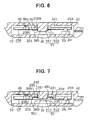
- FIG. 6 A second embodiment of the present invention will be described with reference to FIG. 6.
- the components similar to those of the first embodiment will be indicated by similar numerals in the following description.
- a protruding height of the spindle 249 and a protruding height of the position-limiting ridge 50 are increased from those of the first embodiment, and a length of a cylindrical engaging portion 232A of a follower 23A is increased from that of the first embodiment.
- a portion of the follower 23A arranged between the reinforcing wall 233 and the cylindrical engaging portion 232A is generally flat.
- a third embodiment of the present invention will be described with reference to FIG. 7.
- the components similar to those of the first embodiment will be indicated by similar numerals in the following description.
- a position-limiting ridge 50B surrounds the outer cylindrical portion 234, and a distal end surface 501 of the position-limiting ridge 50B slidably engages the annular disk portion 235.
- the flat portion 512 of the toothed washer 51 slidably engages the contact portion 236.
- FIGS. 8A and 8B A fourth embodiment of the present invention will be described with reference to FIGS. 8A and 8B.
- the components similar to those of the first embodiment will be indicated by similar numerals in the following description.
- a plurality of position-limiting protrusions 52 protrude from the opposing surface 221 of the cover 22.
- the position-limiting protrusions 52 are arranged in a circle around the spindle 249, and a distal end surface 601 of each position-limiting protrusion 52 slidably engages the contact portion 236.
- the position-limiting protrusions 52 provide functions that are similar to those described with reference to the position-limiting ridge 50 of the first embodiment.
- FIGS. 9A and 9B A fifth embodiment of the present invention will be described with reference to FIGS. 9A and 9B.
- the components similar to those of the first embodiment will be indicated by similar numerals in the following description.
- a cylindrical engaging portion 232B of a follower 23B protrudes toward the carrier 19.
- An inner peripheral surface 237A of the cylindrical engaging portion 232B slidably engages the outer peripheral surface 491 of the spindle 249.
- a contact portion 236B slidably engages the opposing surface 221 of the cover 22.
- a ring-shaped engaging element 53 is engaged around the outer peripheral surface 491 of the spindle 249, and the distal end surface of the cylindrical engaging portion 232B slidably engages the ring-shaped engaging element 53.
- the outer cylindrical portion 234B, the contact portion 236B and the engaging element 53 constitute the space maintaining means.
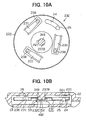
- FIGS. 10A and 10B A sixth embodiment of the present invention will be described with reference to FIGS. 10A and 10B.
- the components similar to those of the first embodiment will be indicated by similar numerals in the following description.
- a spindle supporting recess 54 is recessed toward the carrier 19, and the spindle 249 is fitted within the spindle supporting recess 54.
- a peripheral wall of the spindle supporting recess 54 constitutes a cylindrical engaging portion 232C that protrudes toward the carrier 19.
- a compression spring 55 is held between the follower 23C and the carrier 19. The compression spring 55 urges the follower 23C toward the cover 22.
- a bottom inner surface of the spindle supporting recess 54 slidably engages a distal end surface 492 of the spindle 249, and an inner peripheral surface 237B of the cylindrical engaging portion 232C slidably engages the outer peripheral surface 491 of the spindle 249.
- the spindle 249 and the compression spring 55 constitute the space maintaining means.
- a seventh embodiment of the present invention will be described with reference to FIG. 11.
- the components similar to those of the fifth embodiment will be indicated by similar numerals in the following description.
- a plurality of spindle constituting pieces 56 protrude from the opposing surface 221 of the cover 22.
- Spindle constituting pieces 56 are arranged in a circle to form a spindle for the follower 23B.
- a hook 561 is formed at a distal end of each spindle constituting piece 56.
- the spindle composed of the spindle constituting pieces 56 is inserted within the cylindrical engaging portion 232B while the spindle constituting pieces 56 are resiliently deformed.
- the inner peripheral surface 237A of the cylindrical engaging portion 232B of the follower 23B slidably engages the lateral surfaces of the spindle constituting pieces 56.
- a distal end of the cylindrical engaging portion 232B slidably engages the hooks 561.
- the hooks 561 constitute the space maintaining means.
- FIG. 12 An eighth embodiment of the present invention will be described with reference to FIG. 12. The components similar to those of the first embodiment will be indicated by similar numerals in the following description.
- a cylindrical engaging portion 232D of the follower 23 has an inner diameter larger than an outer diameter of the spindle 249.
- the cylindrical engaging portion 232D of the follower 23 is fitted to the annular position-limiting ridge 50 in such a manner that an outer peripheral surface 237c of the cylindrical engaging portion 232D slidably engages the inner peripheral surface 502 of the position-limiting ridge 50. That is, the position-limiting ridge 50 of the present embodiment constitutes the space maintaining means for maintaining a predetermined space between the follower 23 and the switching pattern 26 and also constitutes a support element for rotatably supporting the follower 23.
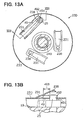
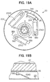
- FIGS. 13A and 13B A ninth embodiment of the present invention will be described with reference to FIGS. 13A and 13B.
- the components similar to those of the first embodiment will be indicated by similar numerals in the following description.
- a follower 23D of the present embodiment does not have the engaging hole 24 of the first embodiment.
- the engaging protrusion 25 is received in a residual hole 49 that is left after cutting and bending of the contact terminal 231.
- the engaging protrusion 25 engages one end 491 of the residual hole 49 upon rotation of the carrier 19 in the forward rotation R.
- a play 493 is provided in the residual hole 49, and the engaging protrusion 25 can move within a range of play 493 within the residual hole 49.
- An engaging wall 492 is formed by burring a corresponding portion of the follower 23D in such a manner that the engaging wall 492 protrudes along a peripheral edge of the residual hole 49 that acts as a driven-side engaging means.
- the residual hole 49 that is formed by cutting and bending of the contact terminal 231 can be conveniently and effectively used as an engaging recess for engaging with the engaging protrusion 25. Furthermore, the use of the residual hole 49 as the engaging recess allows elimination of a dedicated engaging hole for engaging with the engaging protrusion 25, so that a total size of the holes present in the follower 23D is reduced in comparison to that of the first embodiment. Thus, a strength of the follower 23D of the ninth embodiment is greater than that of the follower 23 of the first embodiment.
- FIGS. 14A and 14B A tenth embodiment of the present invention will be described with reference to FIGS. 14A and 14B. The components similar to those of the ninth embodiment will be indicated by similar numerals in the following description.
- a follower 23E of the present embodiment does not have the engaging hole 24 of the first embodiment.
- the engaging protrusion 25 is received in a residual hole 49B that is formed after cutting and bending of a contact terminal 231B.
- a play 493B is provided in the residual hole 49B that acts as the driven-side engaging means, and the engaging protrusion 25 can move within a range of play 493B within the residual hole 49B.
- a base 234 of the contact terminal 231B vertically protrudes, and the engaging protrusion 25 engages the base 234 of the contact terminal 231B upon the rotation of the carrier 19 in the forward rotational direction R.
- the base 234 provides functions similar to those of the engaging walls 241 and 492 formed by burring in the first and ninth embodiments, respectively.
- the step of forming the engaging wall by burring along the peripheral edge of the residual hole 49B can be eliminated.
- FIGS. 15A and 15B An eleventh embodiment of the present invention will be described with reference to FIGS. 15A and 15B. The components similar to those of the tenth embodiment will be indicated by similar numerals in the following description.
- a follower 23F of the present embodiment does not have the engaging hole 24 of the first embodiment.
- the engaging protrusion 25 is received in a residual hole 49C that is left after cutting and bending of a contact terminal 231C.
- a play 493C is provided within the residual hole 49c that acts as a driven-side engaging means, and the engaging protrusion 25 can move within a range of play 493C within the residual hole 49c.
- a base 234 of the contact terminal 231C vertically protrudes, and the engaging protrusion 25 engages the base 234 of the contact terminal 231C upon the rotation of the carrier 19 in the forward rotational direction R.
- the residual hole 49C is an arcuate hole extending along a circle whose center coincides with the rotational axis 161 of the carrier 19.
- a normal rotational direction of the carrier 19 can be used for either one of the forward rotational direction R and the backward rotation.
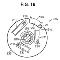
- FIG. 16 A twelfth embodiment of the present invention will be described with reference to FIG. 16. The components similar to those of the first embodiment will be indicated by similar numerals in the following description.
- a follower 23G of the present embodiment has an engaging recess 250 formed along a peripheral edge of the follower 23G.
- the engaging recess 250 extends along a circle whose center coincides with the rotational axis 161 of the output shaft 16.
- the engaging protrusion 25 is received within the engaging recess 250.
- a play 520 is provided in the engaging recess 250 that acts as a driven-side engaging means, and the engaging protrusion 25 can move within a range of play 520 within the engaging recess 250.
- the engaging recess 250 is integrally formed in the follower 23G by press work.
- a reinforcing wall 233 that engages the engaging protrusion 25 provides functions similar to those of the engaging walls 241 and 492 formed by burring in the first and ninth embodiments, respectively.
- FIGS. 17A-17C A thirteenth embodiment of the present invention will be described with reference to FIGS. 17A-17C.
- the components similar to those of the first embodiment will be indicated by similar numerals in the following description.
- an engaging protrusion 610 is integrally formed in the follower 23.
- the engaging protrusion 610 is formed by cutting a corresponding portion of the follower 23 and then bending it toward the carrier 19.
- An engaging recess 524 is formed in the opposing surface 192 of the carrier 19 that opposes the follower 23. A distal end of the engaging protrusion 610 is received within the engaging recess 524 that rotates integrally with the carrier 19.
- the engaging recess 524 is an arcuate groove extending along a circle whose center coincides with the rotational axis 161 of the output shaft 16.
- the distal end of the engaging protrusion 610 engages one circumferential end 521 of the engaging recess 524 to provide surface engagement therebetween.
- the rotation of the carrier 19 is transmitted to the follower 23 through the surface engagement between the engaging protrusion 610 and the circumferential end 521, so that the follower 23 is dragged to rotate about the spindle 249 synchronously with the rotation of the carrier 19.
- a play 522 is provided in the engaging recess 524, and the engaging protrusion 610 can relatively move within a range of play 522 within the engaging recess 524.
- the engaging protrusion 610 is engaged with the circumferential end 521 of the engaging recess 524, i.e., the follower 23 can be immediately rotated upon rotation of the carrier 19 in the forward rotational direction R without a pause.
- the wiper drive motor is forced to rotate backward, the engaging protrusion 610 is relatively moved from the one circumferential end 521 toward the other circumferential end 523 within the engaging recess 524.
- the engaging protrusion 610 that acts as the driven-side engaging means can be easily manufactured through the cutting and bending work. Furthermore, the engaging recess 524 that acts as the driving-side engaging means can be relatively easily manufactured.
- the high manufacturability of the engaging protrusion 610 and the engaging recess 524 contributes to the high manufacturability of the rotational-position sensing device.
- the use of the engaging protrusion 610 that is formed by cutting and bending the metal follower 23 allows a reduction in the number of components of the rotational-position sensing device in comparison to the one in which the engaging protrusion is provided as a separate member.
- Figures 18A-18C show driving-side (540) and driven-side (530) engaging means according to the state of the art.
- an engaging protrusion 530 is integrally formed in the follower 23.
- the engaging protrusion 530 is formed by cutting a corresponding portion of the follower 23 and then bending it toward the carrier 19.
- An engaging protrusion 540 is integrally formed in the opposing surface 192 of the carrier 19 that opposes the follower 23.
- one circumferential end 541 of the engaging protrusion 540 engages one circumferential end of the engaging protrusion 530 to provide surface engagement therebetween (this position is referred to as a first position).
- the rotation of the carrier 19 is transmitted to the follower 23 through the surface engagement between the engaging protrusion 530 and the engaging protrusion 540, so that the follower 23 is dragged to rotate about the spindle 249 synchronously with the rotation of the carrier 19.
- the engaging protrusion 540 can move relative to the engaging protrusion 530 within a range of play 550.
- the engaging protrusion 530 is engaged with the one circumferential end 541 of the engaging protrusion 540, i.e., the follower 23 can be immediately rotated upon rotation of the carrier 19 in the forward rotational direction R without a pause. In this state, if the wiper drive motor is forced to rotate backward, the engaging protrusion 530 is spaced away from the engaging protrusion 540.
- the follower 23 will not be rotated backward by the backward rotation of the carrier 19 or of the wiper drive motor unless the engaging protrusion 540 moves all the way through the range of play 550 relative to the engaging protrusion 530 and engages the other circumferential end surface of the engaging protrusion 530 (this position is referred to as a second position).
- the engaging protrusion 530 that acts as the driven-side engaging means can be easily manufactured through the cutting and bending work, and the engaging protrusion 540 that acts as the driving-side engaging means can be relatively easily manufactured integrally with or separately from the carrier 19.
- the high manufacturability of the engaging protrusions 530 and 540 contributes to the high manufacturability of the rotational-position sensing device.
- the use of the engaging protrusion 530 that is formed by cutting and bending the metal follower 23 allows a reduction in the number of components of the rotational-position sensing device in comparison to the one in which the engaging protrusion is provided as a separate member.
- a sufficient amount of play 550 is provided, so that the arrangement of the fourteenth embodiment can be effectively used in a situation where the large backward rotation of the wiper drive motor is expected.
- FIGS. 19A and 19B A fourteenth embodiment of the present invention will be described with reference to FIGS. 19A and 19B.
- the components similar to those of the first embodiment will be indicated by similar numerals in the following description.
- a rivet shaped contact member 560 penetrates through and is secured to a distal end of a contact terminal 231D that is integrally formed in the follower 23 by cutting a corresponding portion of the follower 23 and then bending it.
- the contact member 560 is made of an electrically conductive material separately from the contact terminal 231D.
- the contact member 560 engages and disengages with the switching pattern 26.
- FIGS. 20A and 20B A fifteenth embodiment of the present invention will be described with reference to FIGS. 20A and 20B.
- the components similar to those of the first embodiment will be indicated by similar numerals in the following description.
- the cover 22 is made of a synthetic resin material, and a circumferential wall surface 222 is formed in the inner surface of the cover 22.
- a central axis of the circumferential wall surface 222 coincides with the rotational axis 161 of the carrier 19.
- a plurality (three in this embodiment) of support projections 223 are formed integrally with the circumferential wall surface 222 to project toward the rotational axis 161.
- a distal end of the output shaft 16 that opposes the cover 22 is covered with a bump 193 that constitutes a part of the carrier 19.
- a plurality (four in this embodiment) of semi-spherical support bulges 194 are integrally formed in a protruding end surface of the bump 193.
- the circumferential wall surface 222 that slidably engages the reinforcing wall 233 of the follower 23H keeps the rotational axis of the follower 23H to substantially coincide with the rotational axis 161 of the carrier 19.
- Each support projection 223 possesses resiliency and resiliently engages the peripheral edge of the follower 23H to rotatably support the follower 23H while preventing the follower 23H from falling out of the cover 22.
- the circumferential wall surface 222 provides radial support for the follower 23H.
- the support projections 223 provide axial support for the follower 23H in the axial direction of the rotational axis 161.
- Each support bulge 194 makes a point contact with a central portion of the follower 23H to support a reaction force exerted from the contact terminals 231 that are urged against the cover 22.
- Each support bulge 194 also minimizes frictional abrasion between the bump 193 and the follower 23H.
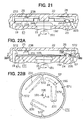
- a sixteenth embodiment of the present invention will be described with reference to FIG. 21.
- the components similar to those of the first and sixteenth embodiments will be indicated by similar numerals in the following description.
- the follower 23 is rotatably fitted around the cylindrical spindle 249.
- the follower 23 is supported by the spindle 249 in such a manner that the rotational axis of the follower 23 coincides with the rotational axis 161 of the carrier 19.
- the spindle 249 provides radial support for the follower 23, and the support projections 223 provide functions similar to those of the support projections 223 of the fifteenth embodiment.
- FIGS. 22A and 22B A seventeenth embodiment of the present invention will be described with reference to FIGS. 22A and 22B. The components similar to those of the sixteenth embodiment will be indicated by similar numerals in the following description.
- the carrier 19 is made of a synthetic resin material, and an annular ridge 57 is integrally formed with the carrier 19 to protrude from a peripheral edge of the opposing surface of the carrier 19 toward the cover 22.
- a circumferential wall surface 571 is formed in an inner peripheral surface of the annular ridge 57.
- a central axis of the circumferential wall surface 571 coincides with the rotational axis 161 of the carrier 19.
- a plurality (four in this embodiment) of support projections 572 are formed integrally with the circumferential wall surface 571 to project toward the rotational axis 161.
- One end of the output shaft 16 that opposes the cover 22 is buried within the carrier 19.
- a semi-spherical support bulge 195 is integrally formed in the carrier 19 to protrude therefrom.
- An engaging protrusion 196 that engages the engaging hole 24 is integrally formed in the carrier 19.
- An annular reinforcing wall 235 is formed along a peripheral edge of a follower 23I by bending a corresponding portion of the follower 23I toward the carrier 19.
- An outer peripheral surface of the reinforcing wall 235 of the follower 23I engages the circumferential wall surface 571.
- the circumferential wall surface 571 that engages the reinforcing wall 235 of the follower 23I keeps the rotational axis of the follower 23I to substantially coincide with the rotational axis 161 of the carrier 19.
- Each support projection 572 possesses resiliency and resiliently engages the peripheral edge of the follower 23I to support the follower 23I while preventing the follower 23I from moving out of the carrier 19.
- the circumferential wall surface 571 provides radial support for the follower 23I.
- the support projections 572 provide axial support for the follower 23I in the axial direction of the rotational axis 161.
- the support bulge 195 supports a reaction force exerted from the contact terminals 231 that are urged against the cover 22. Frictional force is generated between the contact terminals 231 and the cover 22 by urging the contact terminals 231 against the cover 22. Thus, even if the carrier 19 is rotated backward, the follower 23I is held by the frictional force and does not rotate integrally with the carrier 19.
- FIGS. 23A-23C An eightteenth embodiment of the present invention will be described with reference to FIGS. 23A-23C.
- the components similar to those of the first embodiment will be indicated by similar numerals in the following description.
- one end of the output shaft 16 that opposes the cover 22 is covered with a bump 193 that constitutes a part of the carrier 19.
- a spindle 58 and an annular position-limiting ridge 59 are integrally formed in a protruding end surface of the bump 193 to protrude toward the cover 22.
- the annular position-limiting ridge 59 is formed to coaxially surround the spindle 58.
- a central axis of the spindle 58 coincides with the rotational axis 161 of the carrier 19.
- a follower 23J is rotatably fitted around the spindle 58.
- the follower 23J is supported by the spindle 58 in such a manner that the rotational axis of the follower 23J coincides with the rotational axis 161 of the carrier 19.
- the follower 23J is prevented from moving out of the spindle 58 by a detachment preventing ring 60.
- the follower 23J is clamped between the position-limiting ridge 59 and the detachment preventing ring 60.
- the detachment preventing ring 60 limits movement of the follower 23J toward the cover 22 around the spindle 58.
- the position-limiting ridge 59 limits movement of the follower 23J toward the carrier 19 around the spindle 58.
- the position-limiting ridge 59 and the detachment preventing ring 60 maintain a predetermined space between the follower 23J and the switching pattern 26 while supporting the follower 23J in a rotatable manner around the spindle 58.
- FIG. 23B shows a first rotational position 61 in the switching pattern 26 that is provided for sensing a rotational position of the carrier 19 corresponding to a position of the wiper blades.
- the first rotational position 61 is provided for indicating the rotational position of the carrier 19 that corresponds to the predetermined stop position of the wiper blades.
- the first rotational position 61 that is a part of the inner surface of the cover 22 has a stop projection 611.
- the stop projection 611 axially protrudes beyond an electrical wiring portion 261 of the switching pattern 26 that is electrically connected to the contact 238 of the contact terminal 231 upon contacting the contact 238 of the contact terminal 231.
- the stop projection 611 allows the contact 238 of the contact terminal 231 to pass over the stop projection 611 when the carrier 19 is rotated in the forward rotational direction, and the stop projection 611 restrains the contact 238 of the contact terminal 231 from passing over the stop projection 611 when the carrier 19 is rotated in the backward rotational direction (i.e., the contact terminal 231 shown in FIG. 23B can move continuously beyond the stop projection 611 in a right direction in FIG. 23B but is restrained from moving over the stop projection 611 in a left direction in FIG. 23B).
- the carrier 19 could be forced to rotate backward right after the contact 238 of the contact terminal 231 passes over the stop projection 611.
- the play 244 within the engaging hole 24 shown in FIG. 23C allows relative movement of the engaging protrusion 25 within the engaging hole 24 when the carrier 19 rotates backward. Since the follower 23J is clamped between the position-limiting ridge 59 and the detachment preventing ring 60, the follower 23J can be dragged to follow the backward rotation of the carrier 19. However, the stop projection 611 restrains the contact 238 of the contact terminal 231 from passing over the stop projection 611 when the carrier 19 rotates backward. When the carrier 19 rotates backward, the stop projection 611 reliably prevents the follower 23J to follow the backward rotation of the carrier 19 at the first rotational position (the predetermined stop position of the wiper blades).
Landscapes
- Engineering & Computer Science (AREA)
- Mechanical Engineering (AREA)
- Control Of Direct Current Motors (AREA)
- Measurement Of Length, Angles, Or The Like Using Electric Or Magnetic Means (AREA)
Claims (24)
- Drehpositionssensor, welcher einen stationären Körper (12, 22), einen Rotor (19) und ein Folgeelement (23, 23A-23J) aufweist, wobei zum stationären Körper (22) ein Schaltmuster (26) gehört, der Rotor (19) mit einem Mitnehmer (25, 196, 524, 540) versehen und im stationären Körper (12) drehbar gelagert ist, das Schaltmuster (26) um die Drehachse (161) des Rotors (19) angeordnet ist, das Folgeelement (23, 23A-23J) mit mehreren Kontakten (231, 231B-231D) versehen ist und vom Rotor (19) über den Mitnehmer (15, 196, 524, 540) um die Drehachse (161) in Drehung gesetzt wird und der Drehpositionssensor die Drehposition des Rotors (19) aus der beim Drehen des Folgeelements (23, 23A-23J) eintretenden Berührung des Schaltmuster (26) durch die Kontakte (231, 231B-231D) und Trennung beider voneinander erfaßt,
wobei das Folgeelement (23, 23A-23J) aus einer elektrisch leitenden, elastischen Metallplatte gefertigt ist, die Kontakte (231, 231B-231D) integrale Bestandteile der elektrisch leitenden Metallplatte sind, das Folgeelement (23, 23A-23J) außerdem eine Mitnehmeraufnahme (24, 49, 49B, 49C, 250, 530, 610) aufweist und durch die Berührung zwischen dem Mitnehmer und der Mitnehmeraufnahme vom vorwärts drehenden Rotor (19) in Vorwärtsdrehung gesetzt wird,
die Mitnehmeraufnahme (24, 49, 49B, 49C, 250, 530, 610) ein Spiel (244, 493, 493B, 493C, 520, 522, 550) für den Mitnehmer aufweist, welches beim Rückwärtsdrehen des Rotors (19) das Aufheben des bei der Vorwärtsdrehung erreichten Kuppelzustandes zwischen dem Mitnehmer und der Aufnahme ermöglicht und das Übertragen der Rückwärtsdrehung des Rotors (19) auf das Folgeelement (23, 23A-23J) verhindert,
wobei der Drehpositionssensor dadurch gekennzeichnet ist, daß
der antriebsseitige Mitnehmer (25, 524) und die antriebsseitige Mitnehmeraufnahme (24, 49, 49B, 49C, 250, 610) als Vorsprung ausgeführt sind,
andererseits der abtriebsseitige Mitnehmer (25, 524) und die abtriebsseitige Mitnehmeraufnahme (24, 49, 49B, 49C, 250, 610) entweder als Ausnehmung oder als Bohrung für den genannten Vorsprung ausgeführt sind, und
wobei die Kontakte (231, 231B-231D) durch Einschneiden der elektrisch leitenden Metallplatte und Biegen der dabei entstehenden Zungen erzeugt werden. - Drehpositionssensor gemäß Anspruch 1,
dadurch gekennzeichnet, daß
der antriebsseitige Mitnehmer (25) ein Vorsprung ist,
die abtriebsseitige Mitnehmeraufnahme (24, 49, 49B, 49C) eine Durchgangsbohrung im Folgeelement (23, 23A-23F, 23H-23J) ist, und
das Folgeelement (23, 23A-23F, 23H-23J) mit einer entlang der peripheren Kante der Aufnahmebohrung (24, 49, 49B, 49C) sich erstreckenden, durch Stanzen erzeugten Wand (241, 492, 234) versehen ist. - Drehpositionssensor gemäß Anspruch 1,
dadurch gekennzeichnet, daß
der antriebsseitige Mitnehmer (25) der genannte Vorsprung ist und
die abtriebsseitige Mitnehmeraufnahme (49, 49B, 49C) die genannte Aufnahmebohrung ist, welche bei der Erzeugung der Kontakte (231, 231B, 231C) durch Einschneiden der elektrisch leitenden Metallplatte und Biegen der dabei entstehenden Zunge sich ergibt. - Drehpositionssensor gemäß Anspruch 1,
dadurch gekennzeichnet, daß
der antriebsseitige Mitnehmer (25) der genannte Vorsprung ist,
die abtriebsseitige Mitnehmeraufnahme (24, 49C) die genannte Aufnahmebohrung ist, welche sich bogenförmig auf einem Kreis erstreckt, dessen Mittelpunkt mit der Drehachse (161) des Rotors (19) übereinstimmt. - Drehpositionssensor gemäß Anspruch 1,
dadurch gekennzeichnet, daß
der antriebsseitige Mietnehmer (25) der genannte Vorsprung ist,
die abtriebsseitige Mitnehmeraufnahme (24, 49, 49B, 49C) die genannte bogenförmige Durchgangsbohrung ist und ein Spiel (244, 493, 493B, 493C) aufweist, welches beim Rückwärtsdrehen de Rotors (19) ein Abgleiten des antriebsseitigen Mitnehmers (25, 196) aus der beim Vorwärtsdrehen erreichten Antriebsposition ermöglicht, und
die Größe des Spiels (244, 493, 493B, 493C) einem Abstand innerhalb der bogenförmigen Durchgangsbohrung (24, 49, 49B, 49C) entspricht. - Drehpositionssensor gemäß Anspruch 1,
dadurch gekennzeichnet, daß
das Folgeelement (23, 23A-23J) von einem am stationären Körper (22) koaxial zum Rotor (19) vorhandenen Stützelement (56, 249) gestützt wird und zwischen dem stationären Körper (22) und dem Rotor (19) angeordnet ist,
wobei der Drehpositionssensor außerdem
ein um das Stützelement (56, 249) angeordnetes Abstandbeibehaltungselement (50, 50B, 52) zum Beibehalten eines bestimmten Abstandes zwischen dem Folgeelement (23, 23A-23J) und dem Schaltmuster (26) und
einen in der Mitte des Folgeelements (23, 23A-23J) angeordneten zylindrischen Aufnahmeabschnitt (232, 232A-232J) mit einer peripheren Fläche (237, 237A, 237B) als Gleitfläche entlang der peripheren Fläche (491) des Stützelements (56, 249) aufweist. - Drehpositionssensor gemäß Anspruch 6,
dadurch gekennzeichnet, daß
das Abstandbeibehaltungselement (50, 50B, 52) ein Positionsbegrenzungsvorsprung ist, welcher sich aus der auf das Folgeelement (23, 23A-23J) gerichteten Fläche (221) des stationären Körpers (22) um das Stützelement (249) erstreckt und entlang dessen Stirnfläche (501, 601) das Folgeelement (23) beim Drehen gleitet. - Drehpositionssensor gemäß Anspruch 7,
dadurch gekennzeichnet, daß
der Positionsbegrenzungsvorsprung (50) ringförmig ausgeführt ist, als Stützelement für das drehende Folgeelement (23) dient und entlang dessen peripherer Fläche (502) die periphere Fläche (237C) des zylindrischen Aufnahmeabschnitts (232D) beim Drehen des Folgeelements (23) gleitet. - Drehpositionssensor gemäß Anspruch 7 oder 8,
dadurch gekennzeichnet, daß
der Positionsbegrenzungsvorsprung (50, 50B) das Stützelement (249) ringförmig umgibt. - Drehpositionssensor gemäß einem der Ansprüche 7 bis 9,
dadurch gekennzeichnet, daß
zum Abstandbeibehaltungselement (50, 50B, 52) auch eine Zahnscheibe (51) mit einem verzahnten Abschnitt (511) und einem glatten Abschnitt (512) gehört, wobei der verzahnte Abschnitt (511) am stationären Körper (22) befestigt ist und der glatte Abschnitt (512) das Folgeelement (23) gleitfähig gegen die Stirnfläche (501, 601) des Positionsbegrenzungsvorsprungs (50, 52) drückt. - Drehpositionssensor gemäß Anspruch 6,
dadurch gekennzeichnet, daß
das Folgeelement (23) einen Kontaktabschnitt (236, 236B), einen zylindrischen Außenabschnitt (234, 234B) und einen ringförmigen glatten Abschnitt (235) aufweist, wobei der Kontaktabschnitt (236, 236B) vom zylindrischen Aufnahmeabschnitt (232, 232B) abgewinkelt sich radial nach außen erstreckt und den stationären Körper (50, 22) berührt, der zylindrische Außenabschnitt (234, 234B) vom Kontaktabschnitt (236, 236B) abgewinkelt sich koaxial zum zylindrischen Aufnahmeabschnitt (232, 232B) axial nach oben erstreckt, der ringförmige glatte Abschnitt (235) vom zylindrischen Außenabschnitt (234, 234B) abgewinkelt sich radial nach außen erstreckt und mit den Kontaktarmen (231) oder dem Schaltmuster (26) versehen ist und zum Abstandbeibehaltungselement (50, 50B, 51, 52) auch der Kontaktabschnitt (236, 236B), der zylindrische Außenabschnitt (234, 234B) und der ringförmige glatte Abschnitt (235) des Folgeelements (23) gehören. - Drehpositionssensor gemäß einem der Ansprüche 6 bis 11,
dadurch gekennzeichnet, daß
das Folgeelement (23, 23A-23J) scheibenförmig ausgeführt ist und eine von dessen peripherer Außenkante sich erstreckende ringförmige Verstärkungswand (233) aufweist. - Scheibenwischvorrichtung, welche einen Wischarm mit daran befestigtem Wischblatt, einen Motor (11) und eine Steuereinheit (45) aufweist, wobei der Motor (11) wiederum einen Drehpositionssensor (44) zum Erfassen der Drehposition des Wischblattes, ein Getriebegehäuse (12) und einen Untersetzungsmechanismus (13, 17) aufweist, zum Getriebegehäuse (12) eine Ausnehmung (121) und ein Deckel (22) zum Bedecken der Ausnehmung (121) gehören, der Untersetzungsmechanismus (13, 17) in der Ausnehmung (121) untergebracht und an eine Abtriebswelle (16) angeschlossen ist, die Steuereinheit (45) einen Wischerschalter (46) aufweist und über den an diesem eingestellten Wischmodus (461, 462, 463) den Motor (11) steuert, um den Wischarm hin und her zu schwenken,
wobei der Drehpositionssensor (44) außerdem aufweist:einen Rotor (19), welcher im Getriebegehäuse (12) drehbar gelagert und mit einem antriebsseitigen Mitnehmer (25, 196, 524, 540) versehen ist und zusammen mit der Abtriebswelle (16) dreht,ein Schaltmuster (26), welches am Deckel (22) um die Drehachse (161) des Rotors (19) angeordnet ist und eine erste Drehposition sowie eine zweite Drehposition definiert, wobei die erste Drehposition einer vorbestimmten Stopposition des Wischblattes und die zweite Drehposition einer von der Stopposition abweichenden Drehposition des Wischblattes entspricht, undein Folgeelement (23, 23A-23J), welches aus einer elektrisch leitenden elastischen Metallplatte gefertigt und mit mehreren Kontakten (231, 231B-231D) sowie einer abtriebsseitigen Mitnehmeraufnahme (24, 49, 49B, 49C, 250, 530, 610) versehen ist, wobei die Kontakte (231, 231B-231D) integrale Bestandteile der elektrisch leitenden Metallplatte sind und mit dem Schaltmuster (26) in Berührung gebracht und von diesem getrennt werden, die abtriebsseitige Mitnehmeraufnahme (24, 49, 49B, 49C, 250, 530, 610) beim Vorwärtsdrehen des Rotors (19) vom antriebsseitigen Mitnehmer (25, 196, 524, 540) um die Drehachse (161) mitgenommen wird und ein Spiel (244, 493, 493B, 493C, 520, 522, 550) hat, welches beim Rückwärtsdrehen des Rotors (19) ein Wegbewegen des antriebsseitigen Mitnehmers (25, 196, 524, 540) aus der beim Vorwärtsdrehen erreichten Drehposition ermöglicht und dadurch ein Rückwärtsdrehen des Folgeelements (23, 23A-23J) verhindert,wobei die Scheibenwischvorrichtung dadurch gekennzeichnet ist, daß
der antriebsseitige Mitnehmer (25, 524) ein Vorsprung oder eine Ausnehmung und die abtriebsseitige Mitnehmeraufnahme (24, 49, 49B, 49C, 250, 610) entweder eine Ausnehmung oder ein Vorsprung ist, der jeweilige Mitnehmer von der jeweiligen Mitnehmeraufnahme aufgenommen wird und die Kontakte (231, 231B-231D) durch Einschneiden der elektrisch leitenden Metallplatte und Biegen der dabei entstehenden Zungen erzeugt werden. - Scheibenwischvorrichtung gemäß Anspruch 13,
dadurch gekennzeichnet, daß
von den Schaltmodi (461, 462, 463) der Schaltmodus (461) der Stoppmodus zum Stoppen des Wischblattes an der vorbestimmten Stopposition ist,
die Steuereinheit (45) bei Auswahl des Stoppmodus (461) am Wischerschalter (46) den Motor (11) zum Bewegen des Wischblattes in die vorbestimmte Stopposition ansteuert, wenn der Drehpositionssensor (44) die zweite Drehposition erfaßt, dann den Motor (11) stoppt, wenn der Drehpositionssensor (44) die erste Drehposition erfaßt. - Scheibenwischvorrichtung gemäß Anspruch 13 oder 14,
dadurch gekennzeichnet, daß
der antriebsseitige Mitnehmer (25) ein Vorsprung ist, die abtriebsseitige Mitnehmeraufnahme (24, 49, 49B, 49C) am Folgeelement (23, 23A-23J) eine Durchgangsbohrung ist und das Folgeelement (23, 23A- 23F, 23H-23J) an der peripheren Kante der Durchgangsbohrung (24, 49, 49B, 49C) eine durch Stanzen erzeugte Aufnahmewand (241, 492, 234) aufweist. - Scheibenwischvorrichtung gemäß einem der Ansprüche 13 bis 15,
dadurch gekennzeichnet, daß
der antriebsseitige Mitnehmer (25) ein Vorsprung ist, die abtriebsseitige Mitnehmeraufnahme (49, 49B, 49C) eine Öffnung ist, welche bei der Erzeugung der Kontakte (231, 231B, 231C) durch Einschneiden der elektrisch leitenden Metallplatte und Biegen der dabei entstehenden Zungen sich ergibt. - Scheibenwischvorrichtung gemäß einem der Ansprüche 13 bis 16,
dadurch gekennzeichnet, daß
der antriebsseitige Mitnehmer (25) ein Vorsprung ist und die abtriebsseitige Mitnehmeraufnahme (49, 49C) eine gekrümmte Bohrung ist, welche sich auf einem Kreis erstreckt, dessen Mittelpunkt mit der Drehachse (161) des Rotors (19) übereinstimmt. - Scheibenwischvorrichtung gemäß einem der Ansprüche 17 bis 17,
dadurch gekennzeichnet, daß
die abtriebsseitige Mitnehmeraufnahme (24, 49, 49B, 49C) ein Langloch ist und ein Spiel (244, 493, 493B, 493C) hat, welches beim Rückwärtsdrehen des Rotors (19) ein Wegbewegen des antriebsseitigen Mitnehmers (25, 196) aus der beim Vorwärtsdrehen erreichten Position ermöglicht,
wobei das Spiel (244, 493, 493B, 493C) dem Bewegungsweg des Mitnehmers in der Mitnehmeraufnahme entspricht. - Scheibenwischvorrichtung gemäß Anspruch 13,
dadurch gekennzeichnet, daß
das Folgeelement (23, 23A-23J) auf einem im Deckel (22) koaxial zum Rotor (19) vorhandenen Stützelement (56, 249) drehbar gelagert und zwischen dem Deckel (22) und dem Rotor (19) angeordnet ist,
wobei die Scheibenwischvorrichtung außerdem
ein Abstandbeibehaltungselement (50, 50B, 52), welches um das Stützelement (56, 249) angeordnet ist und die Beibehaltung eines vorbestimmten Abstandes zwischen dem Folgeelement (23, 23A-23J) und dem Schaltmuster (26) gewährleistet, und einen in der Mitte des Folgeelements (23, 23A-23J) angeordneten zylindrischen Aufnahmeabschnitt (232, 232A-232D) mit einer an der peripheren Fläche (491) des Stützelements (56, 249) gleitfähigen peripheren Fläche (237, 237A, 237B) aufweist. - Scheibenwischvorrichtung gemäß Anspruch 19,
dadurch gekennzeichnet, daß
das Abstandbeibehaltungselement (50, 50B, 52) ein aus der Fläche (221) des Deckels (22) sich erstreckender, um das Stützelement (248) angeordneter und auf das Folgeelement (23, 23A-23J) gerichteter Positionsbegrenzungsvorsprung ist, dessen Stirnfläche (501, 601) als Gleitfläche für das Folgeelement (23) dient. - Scheibenwischvorrichtung gemäß Anspruch 20,
dadurch gekennzeichnet, daß
das der Positionsbegrenzungsvorsprung (50) Ringform hat, dem Folgeelement (23) als Rotationsstütze dient und entlang dessen peripherer Fläche (502) die periphere Fläche (237C) am zylindrischen Aufnahmeabschnitt (232D) des Folgeelements (23) gleitet. - Scheibenwischvorrichtung gemäß Anspruch 20 oder 21,
dadurch gekennzeichnet, daß
der Positionsbegrenzungsvorsprung (50, 50B) Ringform hat und um das Stützelement (249) angeordnet ist. - Scheibenwischvorrichtung gemäß Anspruch 19,
dadurch gekennzeichnet, daß
das Folgeelement (23) außerdem einen Kontaktabschnitt (236, 236B), einen zylindrischen Außenabschnitt (234, 234B) und einen ringscheibenförmigen flachen Abschnitt (235) aufweist,
wobei der Kontaktabschnitt (236, 236B) vom zylindrischen Aufnahmeabschnitt (232, 232B) aus abgewinkelt radial nach außen sich erstreckt und den Deckel (22) berührt, der zylindrische Außenabschnitt (234, 234B) vom Kontaktabschnitt (236, 236B) aus abgewinkelt axial sich erstreckt und koaxial zum zylindrischen Aufnahmeabschnitt (232, 232B) verläuft, der ringscheibenförmige Abschnitt (235) vom zylindrischen Außenabschnitt (234, 234B) abgewinkelt radial nach außen sich erstreckt und entweder mit den Kontakten (231) oder dem Schaltmuster (26) versehen ist und zum Abstandbeibehaltungselement (50, 50B, 51, 52) außerdem der Kontaktabschnitt (236, 236B), der zylindrische Außenabschnitt (234, 234B) sowie der ringscheibenförmige Abschnitt (235) des Folgeelements (23) gehören. - Scheibenwischvorrichtung gemäß einem der Ansprüche 19 bis 23,
dadurch gekennzeichnet, daß
das Folgeelement (23, 23A-23J) Scheibenform hat und eine aus dessen peripherer Kante sich erstreckende ringförmige Verstärkungswand (233) aufweist.
Applications Claiming Priority (8)
| Application Number | Priority Date | Filing Date | Title |
|---|---|---|---|
| JP2000202185 | 2000-07-04 | ||
| JP2000202186 | 2000-07-04 | ||
| JP2000202185 | 2000-07-04 | ||
| JP2000202186 | 2000-07-04 | ||
| JP2001071925A JP2002079912A (ja) | 2000-07-04 | 2001-03-14 | 回転位置検出装置及びワイパ装置 |
| JP2001071925 | 2001-03-14 | ||
| JP2001135715 | 2001-05-07 | ||
| JP2001135715A JP2002081905A (ja) | 2000-07-04 | 2001-05-07 | 回転位置検出装置及びワイパ装置 |
Publications (3)
| Publication Number | Publication Date |
|---|---|
| EP1170182A2 EP1170182A2 (de) | 2002-01-09 |
| EP1170182A3 EP1170182A3 (de) | 2004-04-07 |
| EP1170182B1 true EP1170182B1 (de) | 2006-06-21 |
Family
ID=27481416
Family Applications (1)
| Application Number | Title | Priority Date | Filing Date |
|---|---|---|---|
| EP01115477A Expired - Lifetime EP1170182B1 (de) | 2000-07-04 | 2001-06-27 | Drehpositionssensor und Scheibenwischervorrichtung damit |
Country Status (4)
| Country | Link |
|---|---|
| US (1) | US6366044B2 (de) |
| EP (1) | EP1170182B1 (de) |
| KR (1) | KR20020003514A (de) |
| DE (1) | DE60120839T2 (de) |
Families Citing this family (9)
| Publication number | Priority date | Publication date | Assignee | Title |
|---|---|---|---|---|
| EP1485278A1 (de) * | 2002-03-13 | 2004-12-15 | Robert Bosch Gmbh | Antrieb einer wischeranlage |
| US7392565B2 (en) * | 2002-05-15 | 2008-07-01 | Trico Products Corporation | Tandem windshield wiper system with bellcrank linkage |
| KR101066578B1 (ko) * | 2005-04-04 | 2011-09-22 | 주식회사 포스코 | 압연기 구동모터의 자동 회전 전환장치 |
| JP4850606B2 (ja) | 2006-07-27 | 2012-01-11 | アスモ株式会社 | モータ及びワイパ装置 |
| DE102008042246A1 (de) * | 2008-09-22 | 2010-04-01 | Robert Bosch Gmbh | Scheibenwischerantrieb |
| DE102009045328A1 (de) * | 2009-10-05 | 2011-04-07 | Robert Bosch Gmbh | Schaltungsanordnung zum Betreiben eines Elektromotors |
| JP5901959B2 (ja) * | 2011-12-20 | 2016-04-13 | アスモ株式会社 | 接点端子の製造方法 |
| JP6411916B2 (ja) * | 2015-02-26 | 2018-10-24 | ラピスセミコンダクタ株式会社 | 半導体装置、ワイパシステム、及び移動体制御方法 |
| US10613113B2 (en) * | 2016-06-27 | 2020-04-07 | Smc Corporation | Position detecting device |
Family Cites Families (18)
| Publication number | Priority date | Publication date | Assignee | Title |
|---|---|---|---|---|
| CH116643A (fr) * | 1925-12-24 | 1927-02-16 | Genevoise Instr Physique | Mécanisme de commande à came. |
| US2398007A (en) * | 1944-06-19 | 1946-04-09 | Cutler Hammer Inc | Electric circuit controller |
| US3649990A (en) * | 1970-01-12 | 1972-03-21 | Shosaku Saito | Wiper device for the front windowpane of a motor-vehicle |
| US3719787A (en) * | 1971-06-01 | 1973-03-06 | J Tomecek | Turn signal apparatus with improved switch structure and printed circuit board |
| ATE32792T1 (de) * | 1984-06-29 | 1988-03-15 | Wild Heerbrugg Ag | Mikroskop mit einem binokularen tubus. |
| JPS6135068U (ja) | 1984-08-03 | 1986-03-04 | 自動車電機工業株式会社 | ワイパ−装置 |
| DE3446761C2 (de) * | 1984-12-21 | 1986-10-30 | SWF Auto-Electric GmbH, 7120 Bietigheim-Bissingen | Scheibenwischanlage, insbesondere für Kraftfahrzeuge |
| US4673853A (en) * | 1985-01-18 | 1987-06-16 | Asmo Co., Ltd. | Concealed wiper system |
| DE3512941C2 (de) * | 1985-04-11 | 1994-09-01 | Teves Gmbh Alfred | Scheibenwischeranlage, insbesondere für Kraftfahrzeuge |
| JPS61247542A (ja) * | 1985-04-26 | 1986-11-04 | Nissan Motor Co Ltd | ワイパ−装置 |
| JPH0411887Y2 (de) * | 1985-05-24 | 1992-03-24 | ||
| US5031265A (en) | 1988-03-15 | 1991-07-16 | Asmo Co., Ltd. | Wiper device for wiping a vehicle windshield |
| JPH0367754A (ja) * | 1989-08-04 | 1991-03-22 | Asmo Co Ltd | ワイパ駆動用モータ |
| DE69033206T2 (de) * | 1989-09-27 | 1999-12-09 | Kamitsu Seisakusho Ltd., Itami | Garnaufwickelvorrichtung vom Typ Revolver-Kopf |
| JP2590581Y2 (ja) * | 1992-05-11 | 1999-02-17 | 株式会社ミツバ | ワイパ駆動装置 |
| JPH06135068A (ja) | 1992-10-30 | 1994-05-17 | Canon Inc | 画像形成装置 |
| DE19548824A1 (de) * | 1995-12-27 | 1997-07-03 | Teves Gmbh Alfred | Antriebsvorrichtung für einen Scheibenwischer |
| JPH09229666A (ja) * | 1996-02-27 | 1997-09-05 | Asmo Co Ltd | 移動体の位置検出装置 |
-
2001
- 2001-06-19 US US09/883,351 patent/US6366044B2/en not_active Expired - Fee Related
- 2001-06-27 DE DE60120839T patent/DE60120839T2/de not_active Expired - Fee Related
- 2001-06-27 EP EP01115477A patent/EP1170182B1/de not_active Expired - Lifetime
- 2001-07-03 KR KR1020010039610A patent/KR20020003514A/ko not_active Application Discontinuation
Also Published As
| Publication number | Publication date |
|---|---|
| US6366044B2 (en) | 2002-04-02 |
| KR20020003514A (ko) | 2002-01-12 |
| US20020003411A1 (en) | 2002-01-10 |
| DE60120839T2 (de) | 2007-06-21 |
| DE60120839D1 (de) | 2006-08-03 |
| EP1170182A2 (de) | 2002-01-09 |
| EP1170182A3 (de) | 2004-04-07 |
Similar Documents
| Publication | Publication Date | Title |
|---|---|---|
| EP1170182B1 (de) | Drehpositionssensor und Scheibenwischervorrichtung damit | |
| CN105846634B (zh) | 电动工具 | |
| CN108656035B (zh) | 具有可切换的传动装置的手持式工具机 | |
| KR20070109819A (ko) | 와이퍼 모터 및 와이퍼 장치 | |
| EP1661778A1 (de) | Motorvorrichtung | |
| US7886400B2 (en) | Motor and wiper apparatus having the same | |
| US20020011390A1 (en) | Motor having clutch provided with stopper | |
| US9231458B2 (en) | Rotation plate and motor | |
| US7402926B2 (en) | Actuator device | |
| EP1396923B1 (de) | Getriebemotor | |
| EP1914436B1 (de) | Bremsmechanismus | |
| US20050115339A1 (en) | Starter | |
| EP1139545A2 (de) | Getriebemotor mit Schnecke und Schneckenrad | |
| EP1261512B1 (de) | Nicht umkehrbarer wischerparkstellungsschalter für eine wischerantriebsvorrichtung | |
| CN110785265B (zh) | 旋转工具 | |
| JPH0589121U (ja) | ワイパ駆動装置 | |
| JP2000502971A (ja) | ウインドシールドワイパ用ドライブ機構 | |
| US20210094147A1 (en) | Grinder | |
| JP6525394B2 (ja) | 電動工具 | |
| EP1529702B1 (de) | Kupplungseinrichtung, Motor und Wischersystem | |
| JP2002081905A (ja) | 回転位置検出装置及びワイパ装置 | |
| JP2002079912A (ja) | 回転位置検出装置及びワイパ装置 | |
| JP3831187B2 (ja) | 電動式パワーステアリング装置 | |
| CN217741510U (zh) | 具有改进的位置确定功能的电机组件 | |
| KR101625690B1 (ko) | 워터펌프용 동력전달장치 |
Legal Events
| Date | Code | Title | Description |
|---|---|---|---|
| PUAI | Public reference made under article 153(3) epc to a published international application that has entered the european phase |
Free format text: ORIGINAL CODE: 0009012 |
|
| AK | Designated contracting states |
Kind code of ref document: A2 Designated state(s): AT BE CH CY DE DK ES FI FR GB GR IE IT LI LU MC NL PT SE TR |
|
| AX | Request for extension of the european patent |
Free format text: AL;LT;LV;MK;RO;SI |
|
| PUAL | Search report despatched |
Free format text: ORIGINAL CODE: 0009013 |
|
| AK | Designated contracting states |
Kind code of ref document: A3 Designated state(s): AT BE CH CY DE DK ES FI FR GB GR IE IT LI LU MC NL PT SE TR |
|
| AX | Request for extension of the european patent |
Extension state: AL LT LV MK RO SI |
|
| 17P | Request for examination filed |
Effective date: 20040504 |
|
| 17Q | First examination report despatched |
Effective date: 20040608 |
|
| AKX | Designation fees paid |
Designated state(s): DE FR IT |
|
| GRAP | Despatch of communication of intention to grant a patent |
Free format text: ORIGINAL CODE: EPIDOSNIGR1 |
|
| GRAS | Grant fee paid |
Free format text: ORIGINAL CODE: EPIDOSNIGR3 |
|
| GRAA | (expected) grant |
Free format text: ORIGINAL CODE: 0009210 |
|
| AK | Designated contracting states |
Kind code of ref document: B1 Designated state(s): DE FR IT |
|
| PGFP | Annual fee paid to national office [announced via postgrant information from national office to epo] |
Ref country code: IT Payment date: 20060630 Year of fee payment: 6 |
|
| PGFP | Annual fee paid to national office [announced via postgrant information from national office to epo] |
Ref country code: DE Payment date: 20060706 Year of fee payment: 6 |
|
| PGFP | Annual fee paid to national office [announced via postgrant information from national office to epo] |
Ref country code: FR Payment date: 20060719 Year of fee payment: 6 |
|
| REF | Corresponds to: |
Ref document number: 60120839 Country of ref document: DE Date of ref document: 20060803 Kind code of ref document: P |
|
| ET | Fr: translation filed | ||
| PLBE | No opposition filed within time limit |
Free format text: ORIGINAL CODE: 0009261 |
|
| STAA | Information on the status of an ep patent application or granted ep patent |
Free format text: STATUS: NO OPPOSITION FILED WITHIN TIME LIMIT |
|
| 26N | No opposition filed |
Effective date: 20070322 |
|
| REG | Reference to a national code |
Ref country code: FR Ref legal event code: ST Effective date: 20080229 |
|
| PG25 | Lapsed in a contracting state [announced via postgrant information from national office to epo] |
Ref country code: DE Free format text: LAPSE BECAUSE OF NON-PAYMENT OF DUE FEES Effective date: 20080101 |
|
| PG25 | Lapsed in a contracting state [announced via postgrant information from national office to epo] |
Ref country code: FR Free format text: LAPSE BECAUSE OF NON-PAYMENT OF DUE FEES Effective date: 20070702 |
|
| PG25 | Lapsed in a contracting state [announced via postgrant information from national office to epo] |
Ref country code: IT Free format text: LAPSE BECAUSE OF NON-PAYMENT OF DUE FEES Effective date: 20070627 |