EP1167916B1 - Gehäuse für Winkelmesseinrichtung - Google Patents
Gehäuse für Winkelmesseinrichtung Download PDFInfo
- Publication number
- EP1167916B1 EP1167916B1 EP01114308A EP01114308A EP1167916B1 EP 1167916 B1 EP1167916 B1 EP 1167916B1 EP 01114308 A EP01114308 A EP 01114308A EP 01114308 A EP01114308 A EP 01114308A EP 1167916 B1 EP1167916 B1 EP 1167916B1
- Authority
- EP
- European Patent Office
- Prior art keywords
- housing
- measuring device
- opening
- angle measuring
- lid
- Prior art date
- Legal status (The legal status is an assumption and is not a legal conclusion. Google has not performed a legal analysis and makes no representation as to the accuracy of the status listed.)
- Expired - Lifetime
Links
- 239000004020 conductor Substances 0.000 description 3
- 230000005672 electromagnetic field Effects 0.000 description 2
- 230000013011 mating Effects 0.000 description 2
- 238000000465 moulding Methods 0.000 description 2
- 230000003321 amplification Effects 0.000 description 1
- 238000005452 bending Methods 0.000 description 1
- 230000005540 biological transmission Effects 0.000 description 1
- 230000015572 biosynthetic process Effects 0.000 description 1
- 150000001875 compounds Chemical class 0.000 description 1
- 238000010276 construction Methods 0.000 description 1
- 230000008878 coupling Effects 0.000 description 1
- 238000010168 coupling process Methods 0.000 description 1
- 238000005859 coupling reaction Methods 0.000 description 1
- 238000002788 crimping Methods 0.000 description 1
- 230000009977 dual effect Effects 0.000 description 1
- 239000000428 dust Substances 0.000 description 1
- 238000002474 experimental method Methods 0.000 description 1
- 238000002347 injection Methods 0.000 description 1
- 239000007924 injection Substances 0.000 description 1
- 238000009434 installation Methods 0.000 description 1
- 238000000034 method Methods 0.000 description 1
- 230000004048 modification Effects 0.000 description 1
- 238000012986 modification Methods 0.000 description 1
- 238000003199 nucleic acid amplification method Methods 0.000 description 1
- 238000007493 shaping process Methods 0.000 description 1
- 239000000243 solution Substances 0.000 description 1
- 230000008719 thickening Effects 0.000 description 1
Images


Classifications
-
- G—PHYSICS
- G01—MEASURING; TESTING
- G01D—MEASURING NOT SPECIALLY ADAPTED FOR A SPECIFIC VARIABLE; ARRANGEMENTS FOR MEASURING TWO OR MORE VARIABLES NOT COVERED IN A SINGLE OTHER SUBCLASS; TARIFF METERING APPARATUS; MEASURING OR TESTING NOT OTHERWISE PROVIDED FOR
- G01D5/00—Mechanical means for transferring the output of a sensing member; Means for converting the output of a sensing member to another variable where the form or nature of the sensing member does not constrain the means for converting; Transducers not specially adapted for a specific variable
- G01D5/26—Mechanical means for transferring the output of a sensing member; Means for converting the output of a sensing member to another variable where the form or nature of the sensing member does not constrain the means for converting; Transducers not specially adapted for a specific variable characterised by optical transfer means, i.e. using infrared, visible, or ultraviolet light
- G01D5/32—Mechanical means for transferring the output of a sensing member; Means for converting the output of a sensing member to another variable where the form or nature of the sensing member does not constrain the means for converting; Transducers not specially adapted for a specific variable characterised by optical transfer means, i.e. using infrared, visible, or ultraviolet light with attenuation or whole or partial obturation of beams of light
- G01D5/34—Mechanical means for transferring the output of a sensing member; Means for converting the output of a sensing member to another variable where the form or nature of the sensing member does not constrain the means for converting; Transducers not specially adapted for a specific variable characterised by optical transfer means, i.e. using infrared, visible, or ultraviolet light with attenuation or whole or partial obturation of beams of light the beams of light being detected by photocells
- G01D5/347—Mechanical means for transferring the output of a sensing member; Means for converting the output of a sensing member to another variable where the form or nature of the sensing member does not constrain the means for converting; Transducers not specially adapted for a specific variable characterised by optical transfer means, i.e. using infrared, visible, or ultraviolet light with attenuation or whole or partial obturation of beams of light the beams of light being detected by photocells using displacement encoding scales
- G01D5/3473—Circular or rotary encoders
Definitions
- the invention relates to an angle measuring device according to the preamble of patent claim 1.
- Angle measuring devices are used to measure rotational movements of a rotatably mounted body, in particular a shaft, over one or more revolutions. The rotational movement is detected incrementally or absolutely. In conjunction with gear racks and gears or with threaded spindles, linear movements can also be measured with an angle measuring device.
- connecting cable of the angle measuring device is supplied to an operating voltage and the measuring signals removed and forwarded to a subsequent electronics.
- an opening is provided in known angle measuring devices on the housing of the angle measuring device, through which the connection cable of the angle measuring device can be fed and contacted there with a suitable electrical connection unit.
- an angle measuring device with a cup-shaped, hollow cylindrical housing which has an opening in its base, through which within the housing, an electrical connector for the connection cable, a device for strain relief of the cable and a connecting means, via a shaft of the angle measuring device with a can be connected to be measured body, are accessible.
- This opening is coverable by means of a lid which is hingedly connected to the housing and can be snapped to cover the opening behind a projection of the housing.
- the snap connection between the cover and the housing is particularly stressed when the angle measuring device is exposed to vibrations or strong tensile loads act on the connecting cable.
- a rotary encoder with mounted stator coupling for installation in engines which is an angle measuring device of the aforementioned type.
- This has a large-area recess in a circular rear wall of its housing, through which both a connecting means for fixing a shaft of the angle measuring device to a body to be measured and an electrical connection unit of the angle measuring device are accessible.
- the opening can be covered with a lid, which is fixed by means of a arranged in the region of the outer edge of the rear wall fastening screw on the rear wall of the housing.
- the screw is exposed in the rear wall of the housing corresponding loads when vibrations act on the angle measuring device.
- the DE 297 18 245 U1 shows an angle measuring device in which a housing cover is removably secured by means of several screws to a housing intermediate bottom of the angle measuring device.
- the WO 99/54683 A2 discloses an angle measuring device, in which behind a centrally disposed opening of the housing wall, a connecting means is arranged, which serves for the connection of a shaft of the angle measuring device with a body to be measured, through which opening the connecting means is actuated. This opening can be closed with a cover screw.
- an angle measuring device is described with a cup-shaped, hollow cylindrical housing having in its base surface of the housing forming the rear wall has a first, central opening through which a connecting means can be actuated, which serves to connect a shaft of the angle measuring device with a body to be measured.
- This opening is closed by a holder, which also serves to attach a connection cable to the housing.
- the connection cable is fed to the interior of the housing through a further, off-center opening in the rear wall of the housing, which is closed with a lid which is locked between the housing and the holder and fixes the holder in its position.
- the invention has for its object to provide an angle measuring device of the type mentioned above, which allows simple means a reliable and permanent attachment of the lid on the housing of the angle measuring device.
- an attachment point is provided on the circular housing wall, which is arranged centrally with respect to the housing wall and on which a fixing element is rotatable with respect to the housing wall for fixing the cover.
- the solution according to the invention is also advantageously applicable if in the housing wall an eccentrically formed with respect to the center or outside the center opening is provided, which is to be covered by the lid.
- the off-center with respect to the center of the housing wall arranged or eccentrically formed with respect to the center opening is covered by a lid which is fixed by means of a centrally arranged on the housing wall fastener to the housing wall.
- An electrical connection of the angle measuring device can be arranged behind the at least one opening in the housing wall, which is accessible from outside the housing through the opening, so that the connection can be contacted with a corresponding mating connection of a connecting cable (partially extending outside the housing).
- a connecting means is arranged, which serves for the connection of a codewheel supporting shaft of the angle measuring device with a body to be measured, wherein the opening for actuating the connecting means is provided from outside the housing.
- the electrical connection on the one hand and the connecting means on the other hand are each assigned separate openings in the housing wall, both of which are closed by the same cover.
- the opening assigned to the electrical connection is preferably arranged outside the center of the housing wall, while the opening associated with the connecting means is arranged centrally in the housing wall.
- the electrical connection on the one hand and the connecting means on the other hand associated with a common opening in the housing wall, which is closed by the lid.
- the connecting means is associated with a centrally arranged in the housing wall, circular opening, then this can also serve as an attachment point, via which the lid is fixed to the housing wall.
- a hollow cylindrical section may be formed out of the housing wall concentrically to the circular opening, which forms the attachment point. This section can for example be provided with an internal or an external thread.
- Such a double function of a central, circular opening in the housing wall is also possible if it is not a separate opening at the centrally arranged opening, but if immediately adjacent to this, another eccentrically arranged opening, which should allow, for example, access to an electrical connection of the angle measuring device.
- the centrally disposed, circular opening and the further opening each form a portion of a common eccentric with respect to the center of the housing wall opening formed. It is important that the central, circular portion of the opening is provided over an angle of more than 180 ° with the thread or closure elements of a bayonet closure, so that the associated fastener can be screwed into this portion of the opening.
- angle measuring device As with the known angle measuring devices, it is also possible with the angle measuring device according to the invention readily to provide a device for strain relief of a connecting cable, which is covered by the lid and which is accessible when the lid is removed.
- the device for strain relief comprises a receptacle in the housing wall, in which a portion of the connection cable can be clamped.
- a recess is provided in the housing wall, in which a portion of the connection cable can engage positively.
- cover itself may be provided on its housing wall side facing a molding for receiving a portion of the connecting cable.
- connection cable which is received by the device for strain relief, preferably consists of an electrically conductive sleeve, in particular a crimp sleeve, which is an electrically conductive Making connection between the shield of the connecting cable and the preferably made of an electrically conductive material housing wall.
- a separate, separate from the lid fastener in particular in the form of a screw may be provided.
- This is preferably held captive on the lid, such that it is rotatably held in a corresponding opening of the lid, e.g. by means of a retaining ring, which prevents axial slipping of the fastening element from the cover.
- FIGS. 1 and 2 describes the construction of an angle measuring device with which the rotational movement of a rotating body can be detected. Following this will be based on the FIGS. 3, 4 and 5, 6 two embodiments of a housing for such an angle measuring device explained, the rear wall having a plurality of openings which can be covered by a lid attached centrally on the rear wall.
- the in the FIGS. 1 and 2 illustrated angle measuring device has a shaft 1 for connection to a body 100 to be measured.
- the connection between the shaft 1 and the body 100 to be measured is realized, for example, with a connecting means projecting through the shaft 1 in the form of a screw 2.
- the angle measuring device itself is fastened to a further body via a base body 3.
- the body 100 to be measured is, for example, a motor shaft and the further body is the stationary motor housing.
- the shaft 1 is rotatably mounted in the base body 3, wherein on the shaft 1, a code disk 4 is fixed and / or the shaft 1 via a transmission drives one or more code disks.
- the code disk 4 is scanned in a photoelectric manner by a scanning device 5. Since the code disk 4 is scanned in the transmitted light method, a light source 5.1 in the main body 3 on one side of the code disk 4 and a detector 5.2 on the other side of the code disk 4 is arranged for this purpose.
- the detector 5.2 is located on a printed circuit board 6, on the side facing the code disk 4.
- the circuit board 6 are electrical components 7 for signal shaping - for example, amplification and digitization - arranged by the detector 5.2 scanning signals.
- On the circuit board 6 is still a part 8.1 (electrical connection) of a connector 8.
- the corresponding parts 8.2 (mating connector) of this connector 8 is attached to a leading outward connection cable 80.
- a cup-shaped housing 30 is provided, which is fixed over the circumference by clamping on the base body 3.
- this compound is a press connection.
- the housing 30 has in its interior a device 15 for strain relief of the connecting cable 80.
- This device 15 is an integral part of the housing 30 and comprises a receptacle 36 of the housing 30, in which a firmly connected to the connection cable 80 part 81 engages, whereby a positive connection between the housing 30 and the connecting cable 80 and the part 81 is formed. A pulling force acting on the connecting cable 80 outside the angle measuring device is thereby not transmitted to the plug connection 8.
- the attached to the connecting cable 80 Part 81 is preferably a crimp sleeve which lies over its entire length (or alternatively with a thickening) in the receptacle 36 of the housing 30.
- This crimp sleeve 81 is electrically conductive and is clamped for safe and easy attachment in the receptacle 36 of the housing 30.
- This receptacle 36 is adapted to the shape of the sleeve 81 and partially surrounds this after snapping.
- the crimping sleeve 81 thus establishes an electrical connection between the shield of the connecting cable 80 and the housing 30.
- the housing 30 is thereby connected by means of the connecting cable 80 in a simple manner with the reference potential of a subsequent electronics (counter, control).
- the housing 30 is made for example of an electrically conductive plastic or of an electrically conductive coated plastic - in particular an injection molded part.
- the receptacle 36 is arranged in the housing 30, the connection cable 80 extends in the region of the receptacle 36 at least approximately perpendicular to the longitudinal axis X of the angle-measuring device.
- a closable opening 39 is provided at one axial end of the housing 30.
- This opening 39 is closed by a cover 40, which is described below with reference to FIGS. 3 and 4 is explained in more detail.
- the angle measuring device is on all sides at least dustproof closed and shielded against electromagnetic fields. With the cover 40 removed, the manufacturer of the angle measuring device and the user can connect the connection cable 80 to a part 8.1 of the connector 8 and insert the connecting cable 80 into the device 15 for strain relief.
- the housing 30 is formed so that only the connector part 8.1 is accessible via the housing opening 39 with the lid 40 open from the outside.
- the other components 7 on the circuit board 6 and the printed circuit board 6 itself are covered by the housing 30 even in the open state of the lid 40.
- the screw 2 is also accessible with the lid 40 open.
- the device 15 for strain relief is disposed completely within the radial outer contour of the housing 30 at a distance from the radial outer contour of the main body 3 and housing 30.
- This has the advantage that the connection cable 80 can be bent as desired within a range of the angle measuring device itself from the device 15 to the outer contour. This allows any radial or axial cable output can be selected.
- the fixation of the connection cable 80 for the strain relief must be spaced from the outer contour of the housing 30 at least corresponding to the minimum permissible or possible bending radius of the connection cable 80.
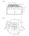
- FIGS. 3 and 4 is the housing 30 of the angle measuring from the FIGS. 1 and 2 shown separately. These figures will be described in addition to the following FIGS. 1 and 2 Reference ..
- the housing 30 is cup-shaped and has a hollow cylinder defining side wall 31 and a base surface of the hollow cylinder defining the rear wall 32.
- a plurality of openings 33, 38, 39 are provided, whose design and function will be explained in more detail below.
- An aperture 39 is provided off-center in the rear wall 32 and extends outwardly to the periphery U of the rear wall 32. This aperture 39 is located entirely outside the midpoint M of the rear wall 32, i. the edge of the opening 39 does not surround the center M.
- an electrical connection of the angle measuring device in the form of a part 8.1 of the connector 8) is provided, which is arranged behind the opening 39 in the housing 30. Accordingly, an end of the connection cable 80 provided with a connector 8.2 can be inserted into the housing 30 through the opening 39 in order to establish an electrical connection there to an electrical connection 8.1 of the angle-measuring device.
- Another eccentric opening 38 in the rear wall 32 of the housing 30 is formed by a web 37 having been crimped in the rear wall 32.
- This web 37 is located next to a passage 34, which is centrally formed out of the rear wall 32.
- the passage 34 is formed as a vertically projecting from the rear wall 32 hollow cylindrical portion whose central axis coincides with the longitudinal axis X of the housing 30. This means that the opening 33 formed by the passage 34 is arranged in the rear wall 32 concentric with the circumference U of the rear wall.
- the opening 33 located centrally in the rear wall 32 of the housing 30 makes it possible to actuate a connection means 2, via which a shaft 1 of the angle measuring device provided with a code disk 4 is connected to a rotating body 100 to be measured (see FIG FIG. 1 ).
- the receptacle 36 is formed, in which a portion of the connection cable 80 of the angle measuring device can be clamped, so that a force acting outside the housing 30 on the cable 80 force not on the electrical connector 8 within of the housing 30 is transmitted.
- This receptacle 36 thus forms part of the device 15 for strain relief of the cable 80th
- connection cable 80 is preferably received in the receptacle 36 on a cable section which has the sleeve 81 made of an electrically conductive material, in particular a crimp sleeve, which is connected to the screen of the connection cable 80.
- the screen of the connecting cable 80 is electrically conductively connected to the housing 30, which preferably consists of an electrically conductive material.
- the openings 33, 38, 39 in the rear wall 32 of the housing 30 are closed by the lid 40 to protect the angle measuring device from dust and shield against electromagnetic fields.
- the lateral edges 41 of the Cover 40 to the surface of the rear wall 32 and to the side wall 31 of the housing 30th
- the cover 40 is on the one hand eccentric with respect to the center M of the rear wall 32 (located on the longitudinal axis X of the angle measuring device) to cover the off-center openings 38, 39 in the rear wall 32, and on the other hand the cover 40 by means of Screw 45 is mounted centrally on the rear wall 32. It has been found that the centric fastening of the cover 40 on the rear wall 32 leads to a vibration-proof fixation of the cover 40. The vibration resistance of the connection between the cover 40 and the housing 30 is thereby promoted by the fact that the fastening screw 45 rests against the internal thread 35 over a large area. This is the result of a correspondingly large-area design of the centrally arranged opening 33 in the rear wall 32, so that the internal thread 35 can be made longer than the thickness of the rear wall 32 itself.
- a preferred embodiment of the embodiment of the FIGS. 3 and 4 is that the fastening screw 45 captive on the Lid 40 is held.
- a fortified on the cover 40 retaining ring may be provided which rotatably receives the fastening screw 45, but axially relative to the cover 40 is not longitudinally displaceable.
- fixation of the cover 40 on the rear wall 32 by screwing a fastener 45 in an associated attachment point 34 does not have to be done via a screw connection.
- a connection may be provided in the manner of a bayonet closure.
- openings 33, 38, 39 are each formed in the rear wall 32 of the housing 30 as separate openings. Thus, two of these openings or all three openings can be combined to form a larger opening.
- FIG. 4 is indicated by a dotted line, the summary of the central opening 33 with one of the off-center openings (opening 39) to an eccentric with respect to the center M of the rear wall 32 formed opening.
- FIGS. 5 and 6 is a modification of the embodiment of the FIGS. 1 to 4 shown.
- the housing 50 of the angle measuring device is cup-shaped with a hollow cylindrical side wall 51 and a circular rear wall 52.
- a central opening 53 in the rear wall 52 is formed by a passage 54 which projects as a hollow cylindrical portion of the rear wall 52 and is provided with an internal thread 55 ,
- the central opening 53 assumes a dual function as in the previous embodiment. On the one hand, it serves as access to a connecting means, via which a shaft of the angle measuring device provided with a code disk can be connected to the body to be measured (identical to the embodiment according to FIG. 1 , therefore not shown here); On the other hand, it forms an attachment point 54, via which a cover 60 can be fixed to the housing 50.
- an opening 59 is arranged through which a connection cable 80 is inserted with its provided with a part 8.2 of the connector 8 end into the housing 50 to there an electrical contact with a disposed within the housing 50 make electrical connection 8.1 of the angle measuring device in the form of a connector 8.
- Another eccentrically arranged opening 58 in the rear wall 52 serves to form a device for strain relief.
- This opening 58 is formed by a notch in the rear wall 52 and is dimensioned such that it can receive an electrically conductive sleeve 81 of the connection cable 80 (in particular a crimp sleeve) in a form-fitting manner.
- the positive reception of the connection cable 80 in the region of the electrically conductive sleeve 81 in the opening 58 prevents forces acting on the cable 80 from being transmitted to the connector 8.
- the connecting cable 80 is guided from the serving for receiving the sleeve 81 opening 58 to the opposite, serving as a passage for the plug part 8.2 opening 59.
- the attachment of the cover 60 on the housing 50 is carried out as in the previous embodiment by means of a fastening or locking screw 65, which passes through the opening 53 in the cover 60 and is screwed into the provided with the internal thread 55 passage 54.
- the lid 60 is formed eccentrically with respect to the center M of the rear wall 52 and covers only a part of the rear wall 52 of the housing 50, so that the cable 80 can be led out on the back wall 52 of the lid 60. In this case, however, all openings 53, 58, 59 in the rear wall 52 of the housing 50 are closed by the cover 60.
- the formation 62 in the cover 60 which receives a portion of the electrically conductive sleeve 81 of the cable 80, formed as a chamber, which Sleeve 81 so radially and axially surrounds that the sleeve 81 is secured within this chamber against axial movement, ie along the extension direction of the connecting cable 80. Consequently, the chamber is an integral part of the device for strain relief.
Landscapes
- Physics & Mathematics (AREA)
- General Physics & Mathematics (AREA)
- Length Measuring Devices With Unspecified Measuring Means (AREA)
- Transmission And Conversion Of Sensor Element Output (AREA)
- Measurement Of Length, Angles, Or The Like Using Electric Or Magnetic Means (AREA)
- A Measuring Device Byusing Mechanical Method (AREA)
- Body Structure For Vehicles (AREA)
- Connector Housings Or Holding Contact Members (AREA)
Applications Claiming Priority (2)
| Application Number | Priority Date | Filing Date | Title |
|---|---|---|---|
| DE10031302 | 2000-06-27 | ||
| DE10031302A DE10031302A1 (de) | 2000-06-27 | 2000-06-27 | Winkelmeßrichtung |
Publications (3)
| Publication Number | Publication Date |
|---|---|
| EP1167916A2 EP1167916A2 (de) | 2002-01-02 |
| EP1167916A3 EP1167916A3 (de) | 2003-10-22 |
| EP1167916B1 true EP1167916B1 (de) | 2008-10-15 |
Family
ID=7646986
Family Applications (1)
| Application Number | Title | Priority Date | Filing Date |
|---|---|---|---|
| EP01114308A Expired - Lifetime EP1167916B1 (de) | 2000-06-27 | 2001-06-13 | Gehäuse für Winkelmesseinrichtung |
Country Status (6)
| Country | Link |
|---|---|
| US (1) | US6617571B2 (enExample) |
| EP (1) | EP1167916B1 (enExample) |
| JP (1) | JP4912537B2 (enExample) |
| AT (1) | ATE411506T1 (enExample) |
| DE (2) | DE10031302A1 (enExample) |
| ES (1) | ES2313921T3 (enExample) |
Families Citing this family (27)
| Publication number | Priority date | Publication date | Assignee | Title |
|---|---|---|---|---|
| DE20218228U1 (de) * | 2002-11-25 | 2004-04-08 | Hengstler Gmbh | Winkeldrehgeber mit Zugentlastung im Deckel |
| DE10316870A1 (de) | 2003-04-11 | 2004-10-21 | Dr. Johannes Heidenhain Gmbh | Positionsmesseinrichtung |
| WO2005053021A2 (en) * | 2003-11-19 | 2005-06-09 | Heat Technology, Inc. | Thermal interface and method of making the same |
| DE102004007445A1 (de) | 2004-02-13 | 2005-09-01 | Dr. Johannes Heidenhain Gmbh | Winkelmesseinrichtung |
| DE102004060864A1 (de) * | 2004-12-17 | 2006-06-22 | Dr. Johannes Heidenhain Gmbh | Winkelmesseinrichtung |
| US20060187573A1 (en) * | 2005-02-24 | 2006-08-24 | Electro-Sensors, Inc. | Sensor equipment guard |
| DE202005006379U1 (de) * | 2005-04-21 | 2006-08-24 | Hengstler Gmbh | Hohlwellen-Drehgeber mit Motorwellen-Schutzkappe |
| JP2007147381A (ja) * | 2005-11-25 | 2007-06-14 | Ntn Corp | 回転角検出センサ |
| US20070131852A1 (en) * | 2005-12-14 | 2007-06-14 | Bryce Welch | Optical encoder, system and method for using the same |
| US7438588B2 (en) | 2006-12-13 | 2008-10-21 | Renco Encoders, Inc. | Encoder and encoder cover with strain relief |
| US20090050080A1 (en) * | 2007-08-24 | 2009-02-26 | Abet Technologies, Llc | Hydrogen peroxide-fueled rotary expansion engine |
| US20090095074A1 (en) * | 2007-10-12 | 2009-04-16 | Yevgeniy Vinshtok | Sensor housing |
| US8497468B2 (en) * | 2007-12-20 | 2013-07-30 | Heidenhain Corporation | Encoder having an overmolded cover, encoder system with an encoder having an overmolded cover, and method for manufacturing an encoder having an overmolded cover |
| DE102008008278A1 (de) * | 2008-02-07 | 2009-08-13 | Dr. Johannes Heidenhain Gmbh | Winkelmesseinrichtung |
| DE102010027900A1 (de) * | 2010-04-19 | 2011-10-20 | Dr. Johannes Heidenhain Gmbh | Baueinheit für eine Winkelmesseinrichtung |
| DE102011005113A1 (de) * | 2011-03-04 | 2012-09-06 | Zf Friedrichshafen Ag | Gehäuse und Abdeckungselement für einen Sensorträger |
| JP5750325B2 (ja) * | 2011-07-15 | 2015-07-22 | 山洋電気株式会社 | エンコーダ |
| DE102011084411B4 (de) * | 2011-10-13 | 2020-07-16 | Dr. Johannes Heidenhain Gmbh | Winkelmesseinrichtung |
| DE102013209106A1 (de) * | 2013-05-16 | 2014-12-04 | Dr. Johannes Heidenhain Gmbh | Winkelmesseinrichtung |
| DE102013223912A1 (de) * | 2013-11-22 | 2015-05-28 | Zf Friedrichshafen Ag | Sensorvorrichtung und Verfahren zum Herstellen einer Sensorvorrichtung |
| DE102013223913A1 (de) * | 2013-11-22 | 2015-05-28 | Zf Friedrichshafen Ag | Sensorvorrichtung und Verfahren zum Herstellen einer Sensorvorrichtung |
| DE102013224452A1 (de) * | 2013-11-28 | 2015-05-28 | Continental Teves Ag & Co. Ohg | Messaufnehmer für einen Sensor |
| EP3399284B1 (de) * | 2017-05-03 | 2019-07-10 | Dr. Johannes Heidenhain GmbH | Sensoreinheit zur positionsmessung |
| DE102017117759A1 (de) * | 2017-08-04 | 2019-02-07 | Mimatic Gmbh | Sensornachrüstsatz |
| CN112032496B (zh) * | 2020-09-16 | 2025-05-13 | 广西柳州钢铁集团有限公司 | 一种稳定型编码器软连接器 |
| EP4464988A1 (de) * | 2023-05-16 | 2024-11-20 | Leuze electronic GmbH + Co. KG | Sensor mit gehäuse und kabel |
| CN117007088B (zh) * | 2023-10-07 | 2023-12-22 | 深圳市盛泰奇科技有限公司 | 一种用于旋转运动单元结构的编码器 |
Citations (2)
| Publication number | Priority date | Publication date | Assignee | Title |
|---|---|---|---|---|
| DE4304032A1 (de) * | 1993-02-11 | 1994-08-18 | Heidenhain Gmbh Dr Johannes | Winkelmeßeinrichtung |
| WO1999054683A2 (en) * | 1998-04-23 | 1999-10-28 | Stridsberg Innovation Ab | A short optical encoder |
Family Cites Families (9)
| Publication number | Priority date | Publication date | Assignee | Title |
|---|---|---|---|---|
| US4653190A (en) * | 1983-03-25 | 1987-03-31 | Spain Jr Robert A | Displacement transducer accommodating extreme environmental conditions |
| JPS60107520A (ja) * | 1983-11-15 | 1985-06-13 | Matsushita Electric Works Ltd | 光学式ロ−タリ−エンコ−ダ |
| US4899145A (en) * | 1985-07-03 | 1990-02-06 | Shin Meiwa Industry Co., Ltd. | Encoder and method of adjusting magnetic fields of the same |
| EP0776065B1 (de) * | 1995-11-21 | 2000-01-05 | Dr. Johannes Heidenhain GmbH | Winkelmesseinrichtung |
| JP3536069B2 (ja) * | 1996-03-08 | 2004-06-07 | 川崎重工業株式会社 | エンコーダ |
| JP2000074614A (ja) * | 1998-08-31 | 2000-03-14 | Toyota Motor Corp | 回転角度センサ |
| DE19913262A1 (de) * | 1999-03-24 | 2000-09-28 | Heidenhain Gmbh Dr Johannes | Winkelmeßeinrichtung |
| JP2000292118A (ja) * | 1999-04-12 | 2000-10-20 | Alps Electric Co Ltd | 回転角度センサ |
| DE10117197B4 (de) * | 2001-04-05 | 2014-10-09 | Anton Rodi | Drehgeber |
-
2000
- 2000-06-27 DE DE10031302A patent/DE10031302A1/de not_active Withdrawn
-
2001
- 2001-04-26 JP JP2001129203A patent/JP4912537B2/ja not_active Expired - Fee Related
- 2001-06-13 EP EP01114308A patent/EP1167916B1/de not_active Expired - Lifetime
- 2001-06-13 AT AT01114308T patent/ATE411506T1/de not_active IP Right Cessation
- 2001-06-13 DE DE50114412T patent/DE50114412D1/de not_active Expired - Lifetime
- 2001-06-13 ES ES01114308T patent/ES2313921T3/es not_active Expired - Lifetime
- 2001-06-25 US US09/891,040 patent/US6617571B2/en not_active Expired - Fee Related
Patent Citations (2)
| Publication number | Priority date | Publication date | Assignee | Title |
|---|---|---|---|---|
| DE4304032A1 (de) * | 1993-02-11 | 1994-08-18 | Heidenhain Gmbh Dr Johannes | Winkelmeßeinrichtung |
| WO1999054683A2 (en) * | 1998-04-23 | 1999-10-28 | Stridsberg Innovation Ab | A short optical encoder |
Also Published As
| Publication number | Publication date |
|---|---|
| DE50114412D1 (de) | 2008-11-27 |
| EP1167916A2 (de) | 2002-01-02 |
| JP2002048532A (ja) | 2002-02-15 |
| ATE411506T1 (de) | 2008-10-15 |
| ES2313921T3 (es) | 2009-03-16 |
| EP1167916A3 (de) | 2003-10-22 |
| DE10031302A1 (de) | 2002-01-10 |
| US20020000512A1 (en) | 2002-01-03 |
| US6617571B2 (en) | 2003-09-09 |
| JP4912537B2 (ja) | 2012-04-11 |
Similar Documents
| Publication | Publication Date | Title |
|---|---|---|
| EP1167916B1 (de) | Gehäuse für Winkelmesseinrichtung | |
| DE19936300B4 (de) | Druckerkennungsvorrichtung und Druckerkennungsvorrichtung-Anordnung hiermit | |
| EP3861293B1 (de) | Haltevorrichtung für einen drehgeber | |
| WO1996035245A1 (de) | Steckverbinder mit einem stecker und einer buchse | |
| DE602004008842T2 (de) | Steckverbindungsgerät für kompakte Stellmotoren | |
| WO2001036903A1 (de) | Messseil-wegsensor | |
| EP2088399B1 (de) | Winkelmesseinrichtung | |
| DE10355350B4 (de) | Elektromodul | |
| DE19913262A1 (de) | Winkelmeßeinrichtung | |
| EP1564529B1 (de) | Winkelmesseinrichtung | |
| WO2004083792A1 (de) | Kraftmesszelle | |
| DE19549795B4 (de) | Winkelmesseinrichtung | |
| DE602005004621T2 (de) | Messsensor | |
| DE4209205C2 (de) | Winkelsensor | |
| EP0776065B1 (de) | Winkelmesseinrichtung | |
| DE4404543C2 (de) | Anordnung für die Kfz.-Elektrik zur Verbindung eines Anschlußkabels mit einem elektrischen Funktionselement | |
| DE29901548U1 (de) | Näherungsschalter | |
| DE29624207U1 (de) | Winkelmeßsystem | |
| DE69720836T2 (de) | Temperaturfühler | |
| DE10026082C1 (de) | Vorrichtung zur Befestigung eines Sensors an einem Druckmittelzylinder | |
| DE102006017983B4 (de) | Elektrische Steckverbindung | |
| DE10301879B3 (de) | Steckvorrichtungselement mit Montagegewinde | |
| EP4163598B1 (de) | Gehäuse zur aufnahme elektrischer und/oder elektronischer bauteile | |
| EP3647739A1 (de) | Abtasteinheit einer positionsmesseinrichtung | |
| DE9201594U1 (de) | Verbindungsanordnung zwischen einem Masseschirm eines Kabels und einem Gehäuse |
Legal Events
| Date | Code | Title | Description |
|---|---|---|---|
| PUAI | Public reference made under article 153(3) epc to a published international application that has entered the european phase |
Free format text: ORIGINAL CODE: 0009012 |
|
| AK | Designated contracting states |
Kind code of ref document: A2 Designated state(s): AT BE CH CY DE DK ES FI FR GB GR IE IT LI LU MC NL PT SE TR |
|
| AX | Request for extension of the european patent |
Free format text: AL;LT;LV;MK;RO;SI |
|
| PUAL | Search report despatched |
Free format text: ORIGINAL CODE: 0009013 |
|
| AK | Designated contracting states |
Kind code of ref document: A3 Designated state(s): AT BE CH CY DE DK ES FI FR GB GR IE IT LI LU MC NL PT SE TR |
|
| AX | Request for extension of the european patent |
Extension state: AL LT LV MK RO SI |
|
| 17P | Request for examination filed |
Effective date: 20040422 |
|
| AKX | Designation fees paid |
Designated state(s): AT BE CH CY DE DK ES FI FR GB GR IE IT LI LU MC NL PT SE TR |
|
| 17Q | First examination report despatched |
Effective date: 20080415 |
|
| GRAP | Despatch of communication of intention to grant a patent |
Free format text: ORIGINAL CODE: EPIDOSNIGR1 |
|
| GRAS | Grant fee paid |
Free format text: ORIGINAL CODE: EPIDOSNIGR3 |
|
| GRAA | (expected) grant |
Free format text: ORIGINAL CODE: 0009210 |
|
| AK | Designated contracting states |
Kind code of ref document: B1 Designated state(s): AT BE CH CY DE DK ES FI FR GB GR IE IT LI LU MC NL PT SE TR |
|
| REG | Reference to a national code |
Ref country code: CH Ref legal event code: EP Ref country code: GB Ref legal event code: FG4D Free format text: NOT ENGLISH Ref country code: CH Ref legal event code: NV Representative=s name: TROESCH SCHEIDEGGER WERNER AG |
|
| REG | Reference to a national code |
Ref country code: IE Ref legal event code: FG4D Free format text: LANGUAGE OF EP DOCUMENT: GERMAN |
|
| REF | Corresponds to: |
Ref document number: 50114412 Country of ref document: DE Date of ref document: 20081127 Kind code of ref document: P |
|
| REG | Reference to a national code |
Ref country code: ES Ref legal event code: FG2A Ref document number: 2313921 Country of ref document: ES Kind code of ref document: T3 |
|
| NLV1 | Nl: lapsed or annulled due to failure to fulfill the requirements of art. 29p and 29m of the patents act | ||
| PG25 | Lapsed in a contracting state [announced via postgrant information from national office to epo] |
Ref country code: NL Free format text: LAPSE BECAUSE OF FAILURE TO SUBMIT A TRANSLATION OF THE DESCRIPTION OR TO PAY THE FEE WITHIN THE PRESCRIBED TIME-LIMIT Effective date: 20081015 Ref country code: FI Free format text: LAPSE BECAUSE OF FAILURE TO SUBMIT A TRANSLATION OF THE DESCRIPTION OR TO PAY THE FEE WITHIN THE PRESCRIBED TIME-LIMIT Effective date: 20081015 Ref country code: PT Free format text: LAPSE BECAUSE OF FAILURE TO SUBMIT A TRANSLATION OF THE DESCRIPTION OR TO PAY THE FEE WITHIN THE PRESCRIBED TIME-LIMIT Effective date: 20090316 |
|
| REG | Reference to a national code |
Ref country code: IE Ref legal event code: FD4D |
|
| PG25 | Lapsed in a contracting state [announced via postgrant information from national office to epo] |
Ref country code: DK Free format text: LAPSE BECAUSE OF FAILURE TO SUBMIT A TRANSLATION OF THE DESCRIPTION OR TO PAY THE FEE WITHIN THE PRESCRIBED TIME-LIMIT Effective date: 20081015 Ref country code: IE Free format text: LAPSE BECAUSE OF FAILURE TO SUBMIT A TRANSLATION OF THE DESCRIPTION OR TO PAY THE FEE WITHIN THE PRESCRIBED TIME-LIMIT Effective date: 20081015 |
|
| PLBE | No opposition filed within time limit |
Free format text: ORIGINAL CODE: 0009261 |
|
| STAA | Information on the status of an ep patent application or granted ep patent |
Free format text: STATUS: NO OPPOSITION FILED WITHIN TIME LIMIT |
|
| PG25 | Lapsed in a contracting state [announced via postgrant information from national office to epo] |
Ref country code: SE Free format text: LAPSE BECAUSE OF FAILURE TO SUBMIT A TRANSLATION OF THE DESCRIPTION OR TO PAY THE FEE WITHIN THE PRESCRIBED TIME-LIMIT Effective date: 20090115 |
|
| 26N | No opposition filed |
Effective date: 20090716 |
|
| BERE | Be: lapsed |
Owner name: DR. JOHANNES HEIDENHAIN G.M.B.H. Effective date: 20090630 |
|
| PG25 | Lapsed in a contracting state [announced via postgrant information from national office to epo] |
Ref country code: MC Free format text: LAPSE BECAUSE OF NON-PAYMENT OF DUE FEES Effective date: 20090630 |
|
| REG | Reference to a national code |
Ref country code: FR Ref legal event code: ST Effective date: 20100226 |
|
| PG25 | Lapsed in a contracting state [announced via postgrant information from national office to epo] |
Ref country code: FR Free format text: LAPSE BECAUSE OF NON-PAYMENT OF DUE FEES Effective date: 20090630 |
|
| PG25 | Lapsed in a contracting state [announced via postgrant information from national office to epo] |
Ref country code: BE Free format text: LAPSE BECAUSE OF NON-PAYMENT OF DUE FEES Effective date: 20090630 |
|
| PG25 | Lapsed in a contracting state [announced via postgrant information from national office to epo] |
Ref country code: AT Free format text: LAPSE BECAUSE OF NON-PAYMENT OF DUE FEES Effective date: 20090613 |
|
| PG25 | Lapsed in a contracting state [announced via postgrant information from national office to epo] |
Ref country code: GR Free format text: LAPSE BECAUSE OF FAILURE TO SUBMIT A TRANSLATION OF THE DESCRIPTION OR TO PAY THE FEE WITHIN THE PRESCRIBED TIME-LIMIT Effective date: 20090116 |
|
| PG25 | Lapsed in a contracting state [announced via postgrant information from national office to epo] |
Ref country code: LU Free format text: LAPSE BECAUSE OF NON-PAYMENT OF DUE FEES Effective date: 20090613 |
|
| PG25 | Lapsed in a contracting state [announced via postgrant information from national office to epo] |
Ref country code: TR Free format text: LAPSE BECAUSE OF FAILURE TO SUBMIT A TRANSLATION OF THE DESCRIPTION OR TO PAY THE FEE WITHIN THE PRESCRIBED TIME-LIMIT Effective date: 20081015 |
|
| PG25 | Lapsed in a contracting state [announced via postgrant information from national office to epo] |
Ref country code: CY Free format text: LAPSE BECAUSE OF FAILURE TO SUBMIT A TRANSLATION OF THE DESCRIPTION OR TO PAY THE FEE WITHIN THE PRESCRIBED TIME-LIMIT Effective date: 20081015 |
|
| PGFP | Annual fee paid to national office [announced via postgrant information from national office to epo] |
Ref country code: IT Payment date: 20180627 Year of fee payment: 18 Ref country code: ES Payment date: 20180720 Year of fee payment: 18 Ref country code: GB Payment date: 20180620 Year of fee payment: 18 |
|
| PGFP | Annual fee paid to national office [announced via postgrant information from national office to epo] |
Ref country code: DE Payment date: 20190619 Year of fee payment: 19 |
|
| PGFP | Annual fee paid to national office [announced via postgrant information from national office to epo] |
Ref country code: CH Payment date: 20190619 Year of fee payment: 19 |
|
| GBPC | Gb: european patent ceased through non-payment of renewal fee |
Effective date: 20190613 |
|
| PG25 | Lapsed in a contracting state [announced via postgrant information from national office to epo] |
Ref country code: GB Free format text: LAPSE BECAUSE OF NON-PAYMENT OF DUE FEES Effective date: 20190613 Ref country code: IT Free format text: LAPSE BECAUSE OF NON-PAYMENT OF DUE FEES Effective date: 20190613 |
|
| REG | Reference to a national code |
Ref country code: ES Ref legal event code: FD2A Effective date: 20201027 |
|
| REG | Reference to a national code |
Ref country code: DE Ref legal event code: R119 Ref document number: 50114412 Country of ref document: DE |
|
| PG25 | Lapsed in a contracting state [announced via postgrant information from national office to epo] |
Ref country code: ES Free format text: LAPSE BECAUSE OF NON-PAYMENT OF DUE FEES Effective date: 20190614 |
|
| REG | Reference to a national code |
Ref country code: CH Ref legal event code: PL |
|
| PG25 | Lapsed in a contracting state [announced via postgrant information from national office to epo] |
Ref country code: LI Free format text: LAPSE BECAUSE OF NON-PAYMENT OF DUE FEES Effective date: 20200630 Ref country code: CH Free format text: LAPSE BECAUSE OF NON-PAYMENT OF DUE FEES Effective date: 20200630 |
|
| PG25 | Lapsed in a contracting state [announced via postgrant information from national office to epo] |
Ref country code: DE Free format text: LAPSE BECAUSE OF NON-PAYMENT OF DUE FEES Effective date: 20210101 |